Overview
I decided to machine a coffee table for myself. I have some experience in making stuff from wood. But instead of joints I always used screws, pegs and wood glue. So I definitely wanted to do joints to learn something new. Also machining wood with a CNC was new for me and added a lot of possibilities, which I never had with traditional methods like a jigsaw, bench saw and drill. So I wanted to add some design details to it I never could before. In the group assignment we looked at basic milling concepts.
Design / Planning
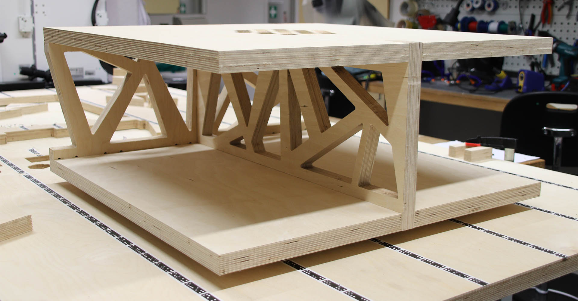
I was already decided on a size for my coffee table, so I decided to not do parametric design to be faster in the modeling. The size of the table is 70cm x 70cm x 30cm. I modeled the table in Fusion 360 and you can see my modeling process in the following video. I started by creating four boards and then adding the details to them by extruding sketches.
The modeling process of my coffee table
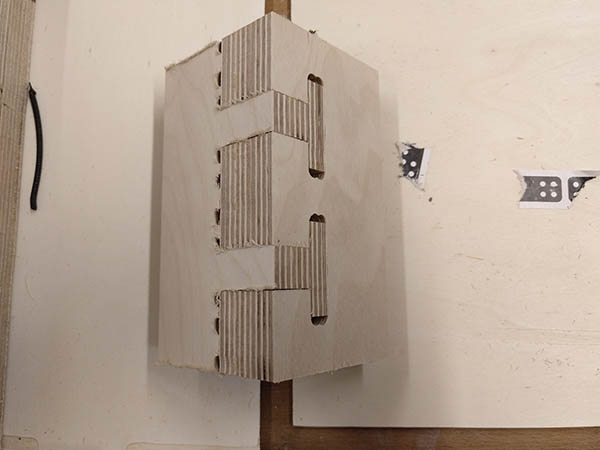
For the joints, I used I first informed myself on the CNC Panel Joinery Notebook and the CNC Cut Wood Joinery site. The second page was most helpful because it was especially for CNC cut wood joints. There I found the Hammer Tenon Joint, which I first wanted to use so that you can pick up the table by just holding it on the upper plate. Only finger joints would need to be very tight to achieve that. In the end, I used finger joints with an inside joint in one wall (see the pictures in assembling), because they achieved the same and would be more hidden. I also added "dogbones" to my design to be able to cut it with a CNC. The joints are designed in OpenSCAD to be parametric.
One thing in Fusion that caused me some headache until I found out how to do it was how to move parts of sketches around in the sketch. This is helpful if you in example want to get the same joint in two positions or want to copy the joint onto the other board.
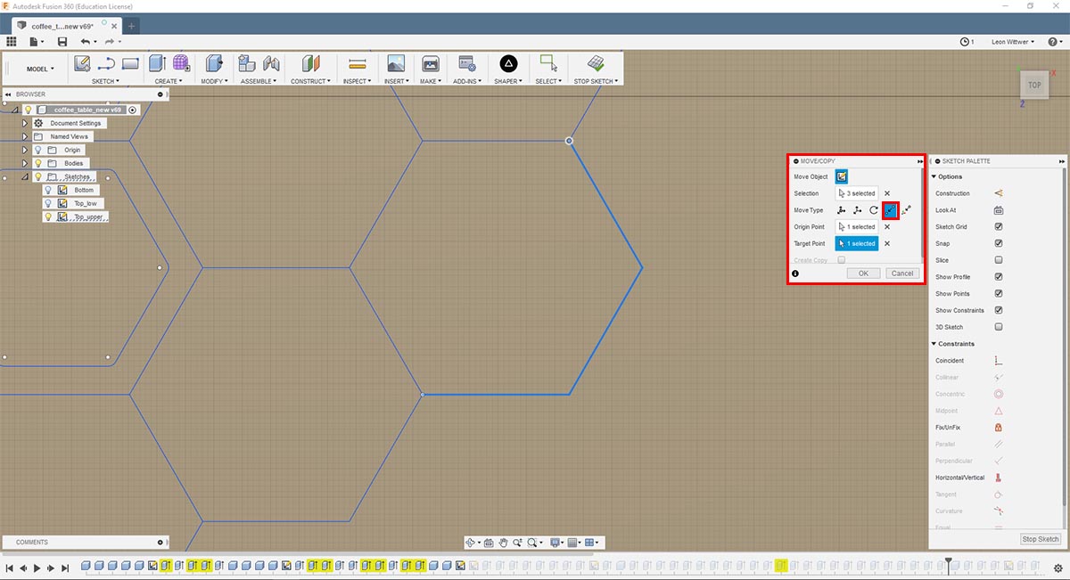
How to move parts of sketches
Therefore you need to select the objects (lines, points) you want to move. Then you choose the MODIFY -> Move/Copy Tool. Or you copy and paste the object, then the tool is opened automatically. There you set the Move Type to Point to Point. Then you can set an Origin Point and a Target Point and it moves exactly to the point where you want it.
Making
We had the opportunity to work with the Shaper Origin, which is a handheld CNC mill. It is nice on the one hand because you can work on wood boards of any size without the need of having such a huge CNC mill. But on the other hand, it is a strenuous task to cut long cuts with this thing. One problem was that we had a 29mm thick wooden board but the shaper could only cut 10mm depth at once. So you had to do every cut three times. Also, it is quite accurate, but if you really need perfectly cut wood it is not accurate enough. It easily happens that it does not cut properly, especially when you have complex cuts.
Setup
To set up the machine you first need to scan the workspace. Beforehand you need to put makertape on the workpiece, so that the shaper can orient itself.
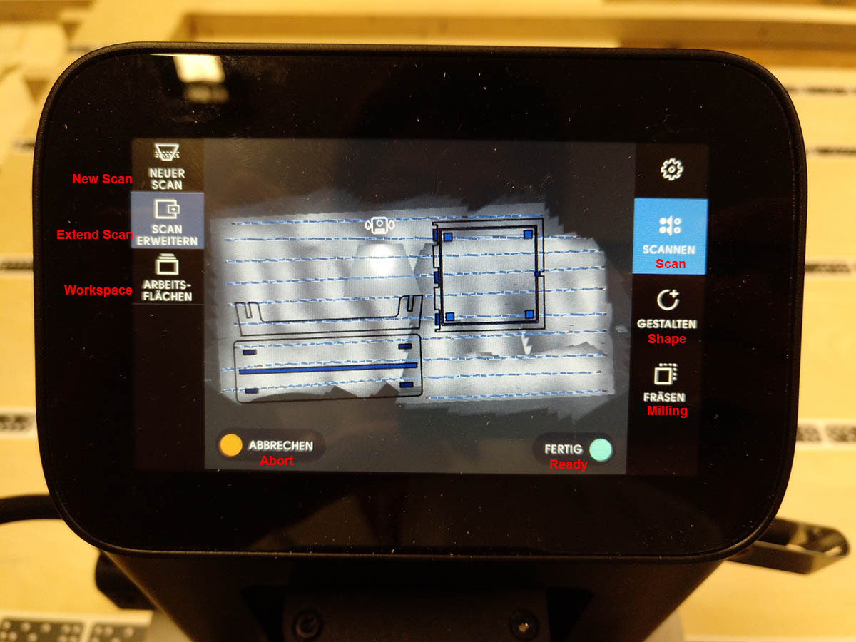
Set up the workspace
Then you need to load and place your part on the workpiece where you want to mill it. Beware that you leave enough border to not fall over with the shaper.
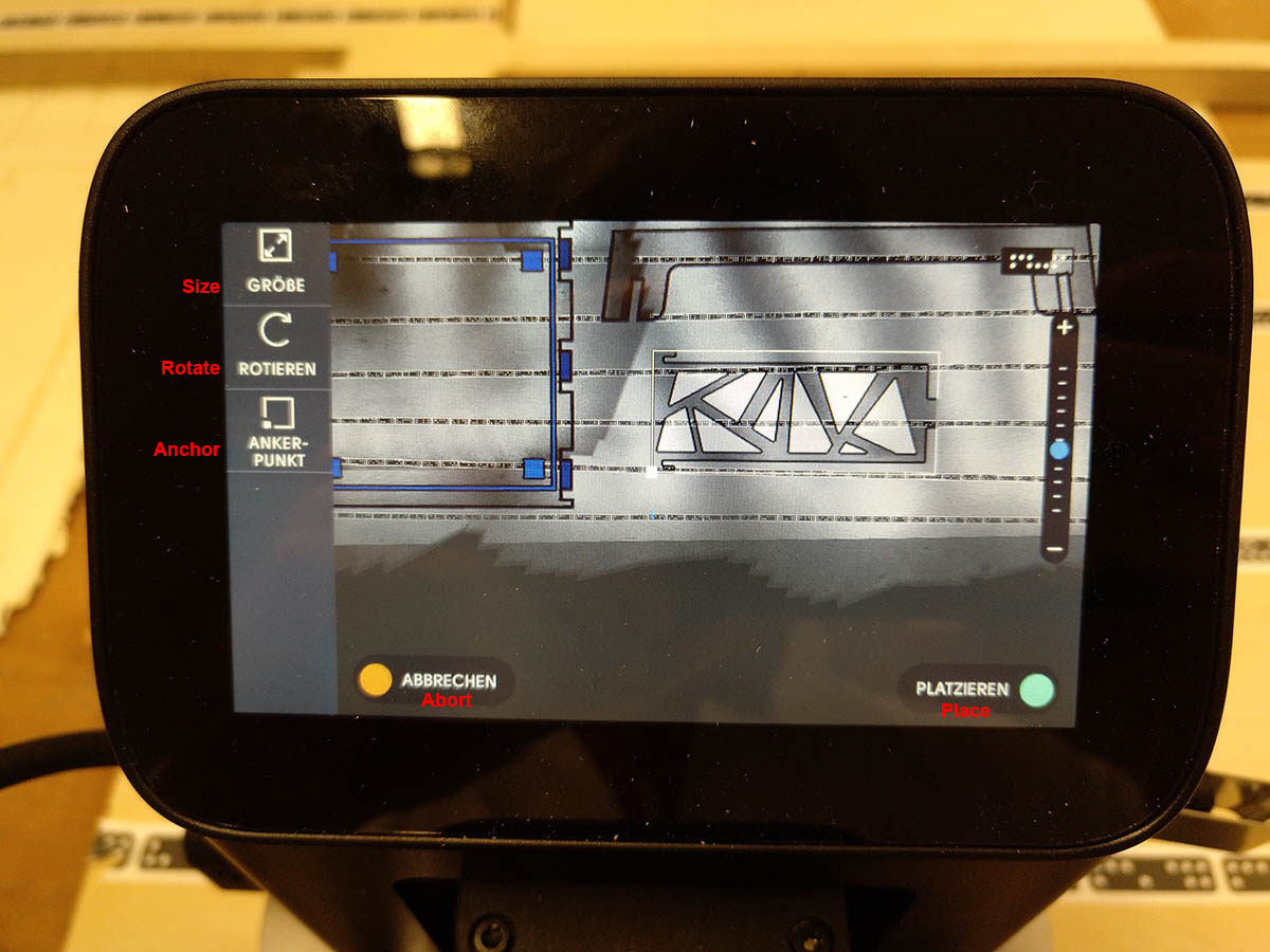
Place your part
Then you come to the actual milling interface. There you can specify (from top to bottom): The depth you want to mill, if you want to mill on the line or on the in-/outside, if you want an offset from the line, which size the drill has, to calibrate the height again (after you put in a new drill) and to set the speed.
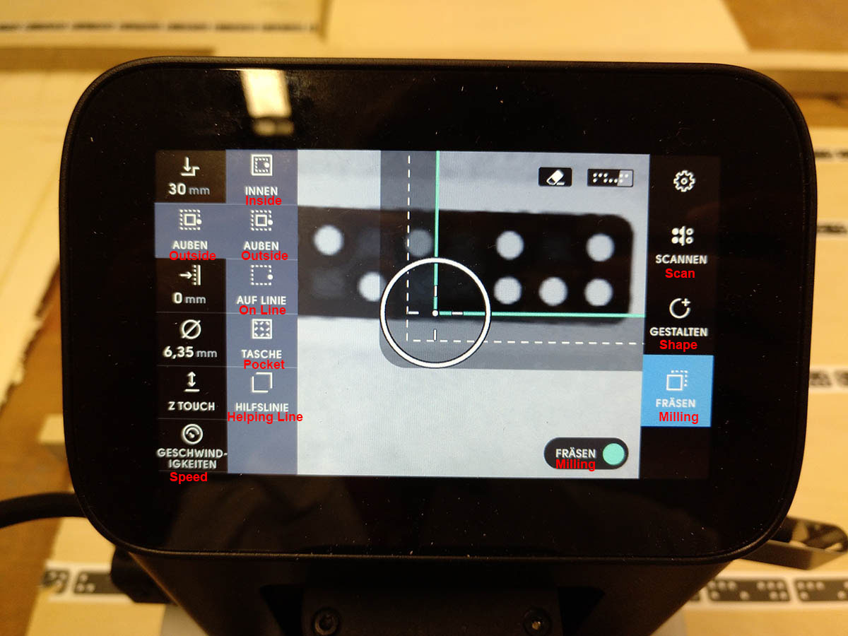
The milling interface
Tests
The first thing I did was an inlay test, to test if I cut do inlays with this CNC. After sanding down the part I could hammer it in. And in the pressed inlay you could definitely see small cleaves, so it didn't fit perfectly.
The cut inlay
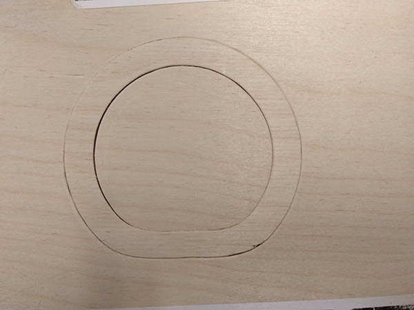
The inlay hammered in
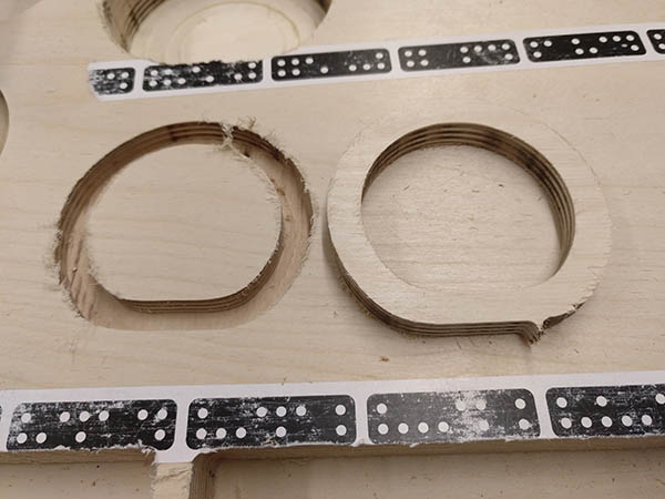
The next thing I did was a test cut of the hammer tenon joint I wanted to use first. This worked out pretty well. If could be joined and also removed again using a hammer. Unfortunately, I decided later to use a different joint.
The hammer tenon joint
The joined joint
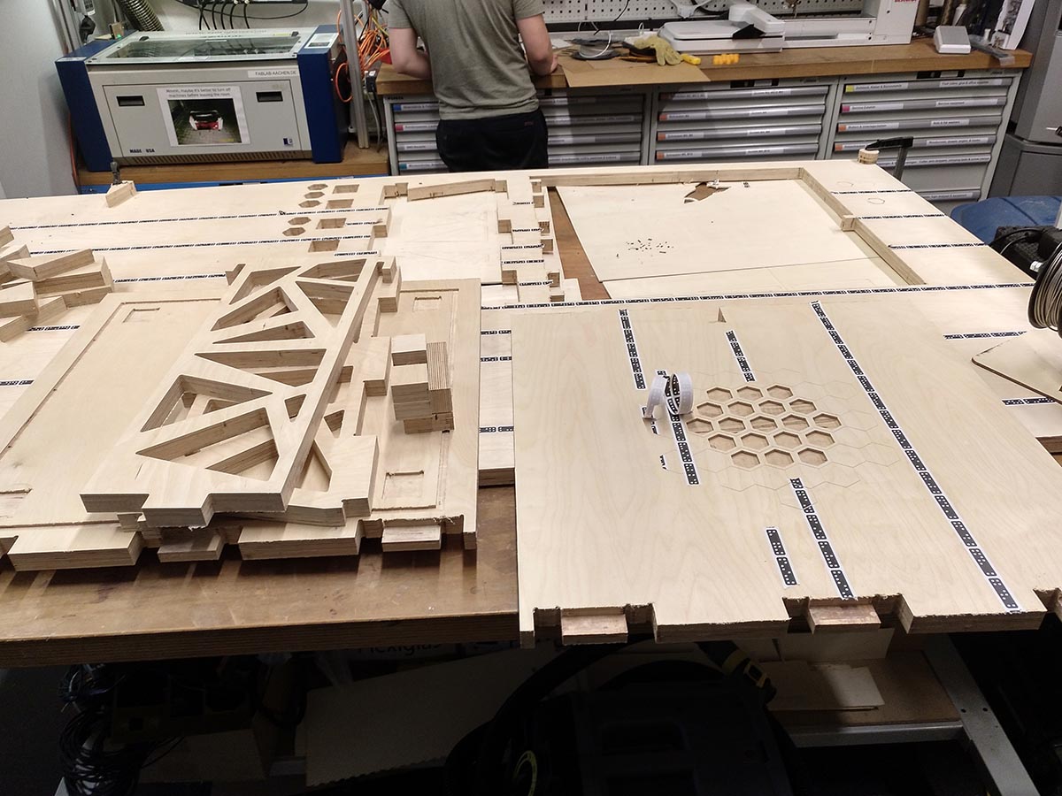
Machining
After all the tests before I was finally able to machine my parts. This process you can see in the following timelapse, which is speed up to 480 times faster. I put cuts to the upper and lower side of one board, and it surprised me to see how good I was able to align the shaper to the turned board. So the cuts were in the right place. You can see me working on the turned plate from second 50 onwards.
Timelapse of machining the parts for the coffee table in 480x speed
Problems
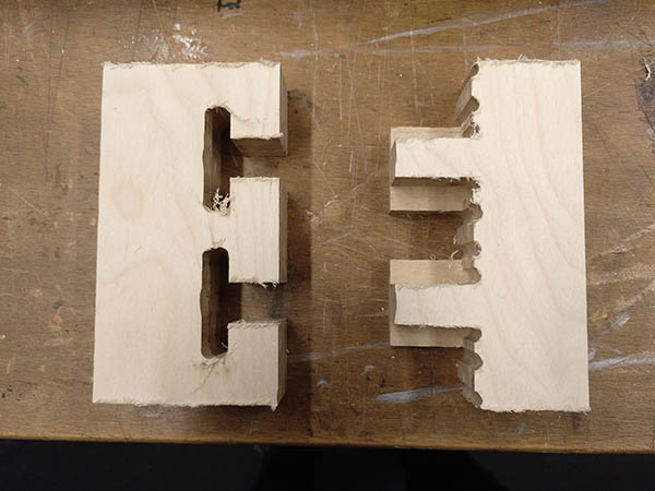
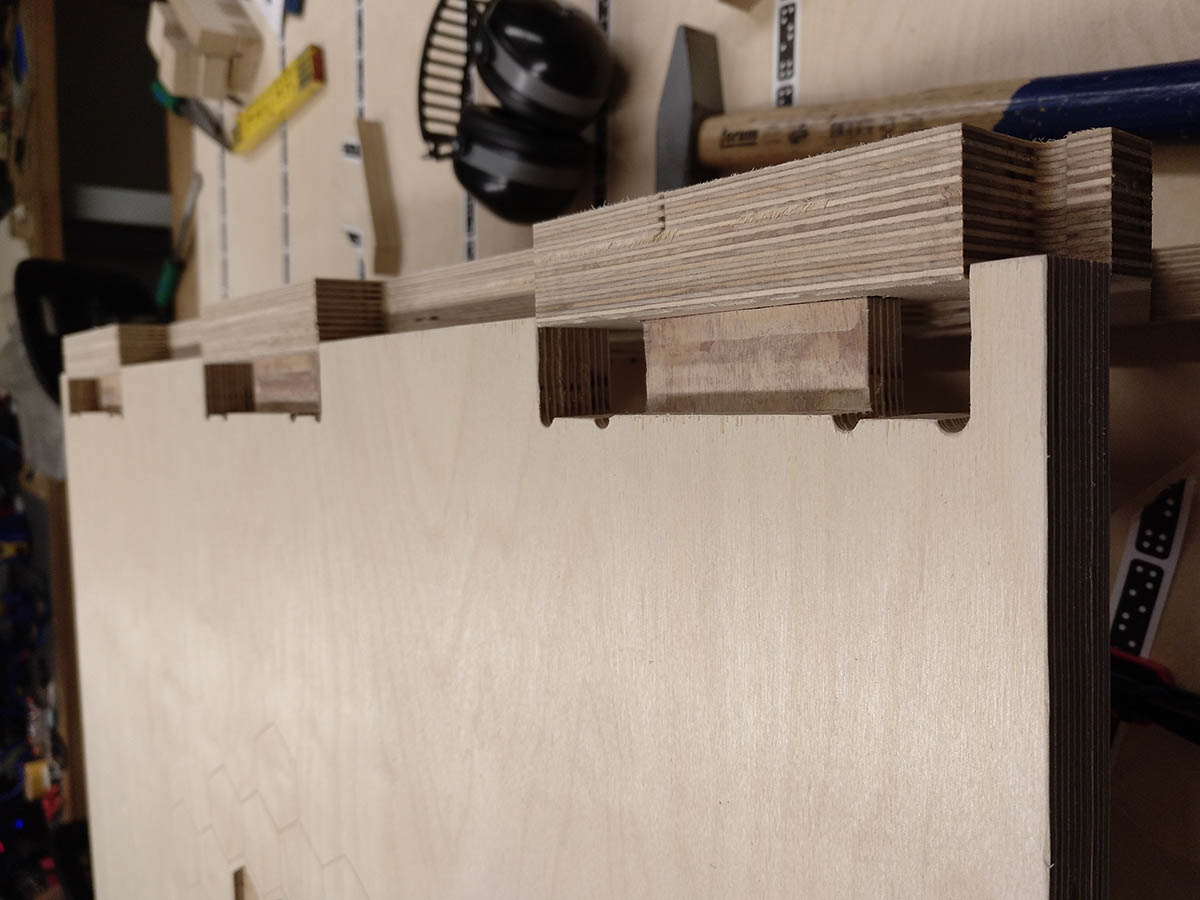
One problem that I had was that I didn't design all the dogbones that I needed. I realized this when I was milling the parts, but then it was too late. So I just used a wood file to remove the excess parts in corners. This worked really good.
Also, I used the wood file and sandpaper to smooth corners and remove wood fibers which were hanging nearly at all the finished cuts on the surface.
Assembling
The assembling of the finished parts needed a lot of force with a hammer, so I am not sure if I can ever remove the parts from each other. Here you can see how the finished parts with joints looked like and how I assembled them:
The finished plates
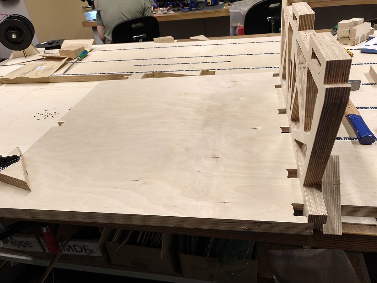
Joining the lower and side plate
Joining the upper and the side plate
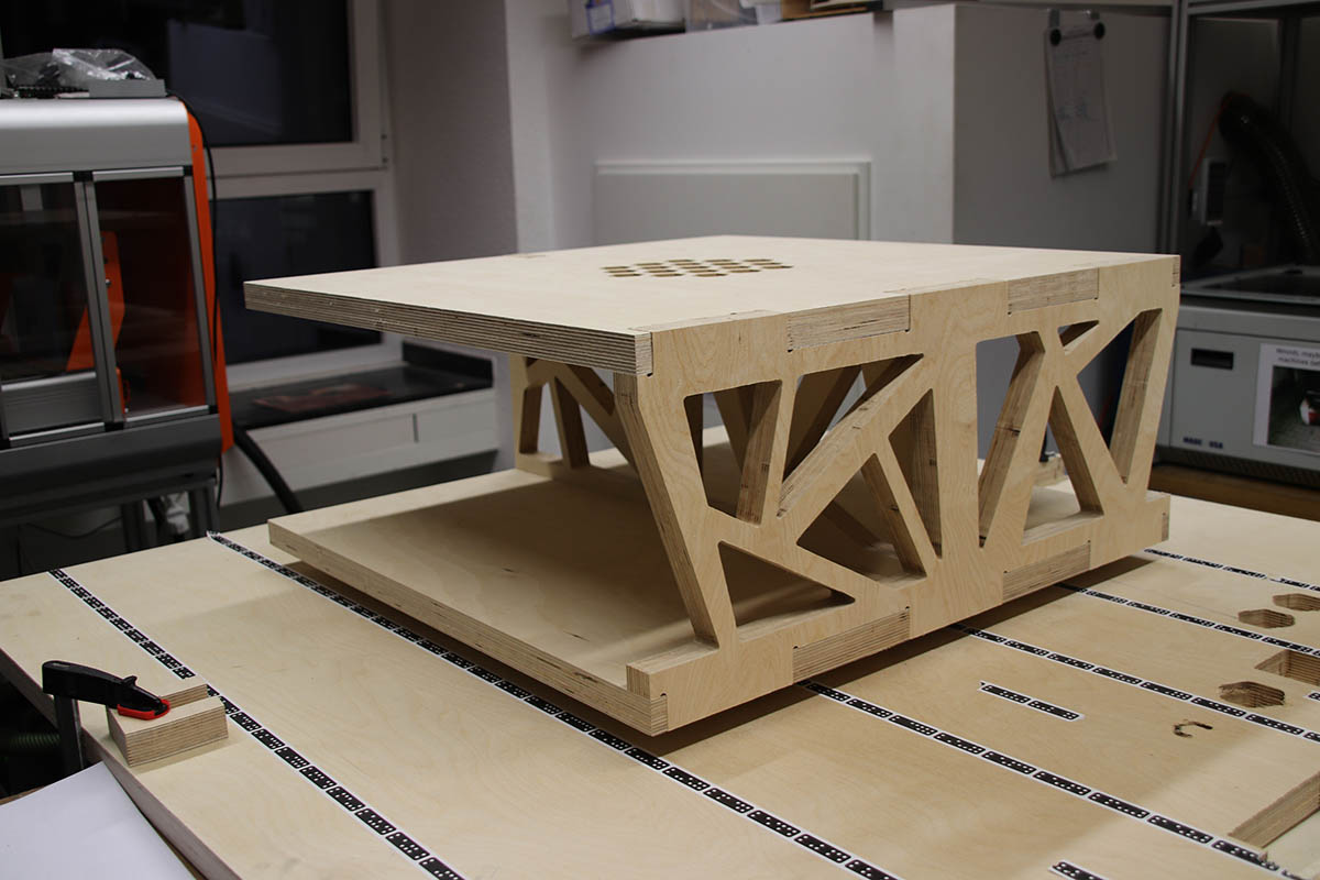
After adding the middle part
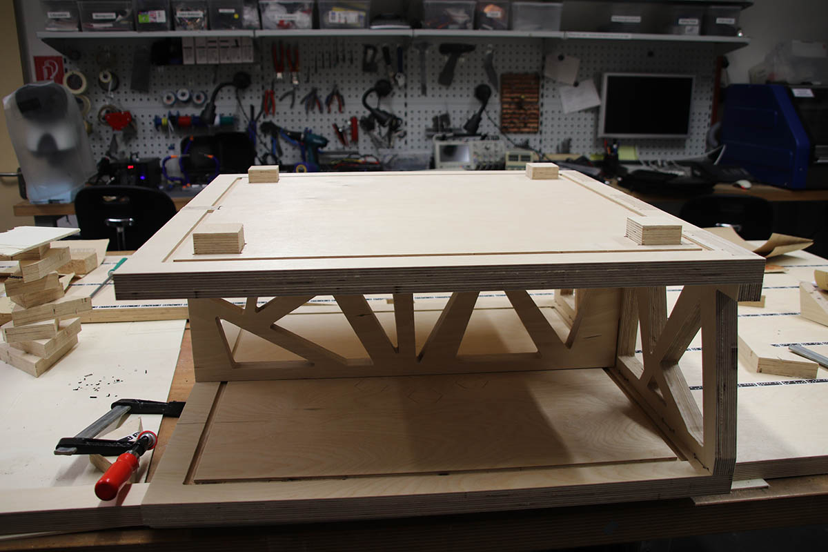
The table upside down, with stands put in
Finished Table
Some detail shots of the finished table
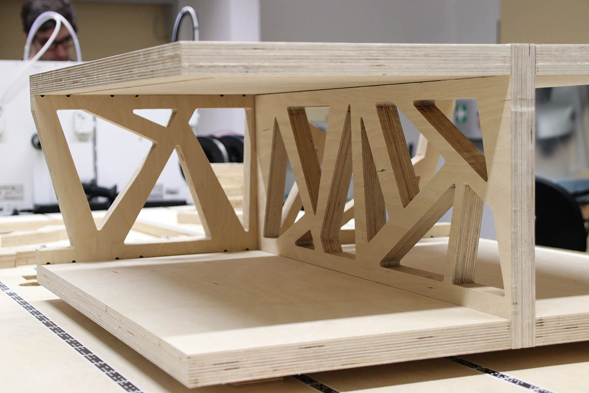
The structure of the side parts
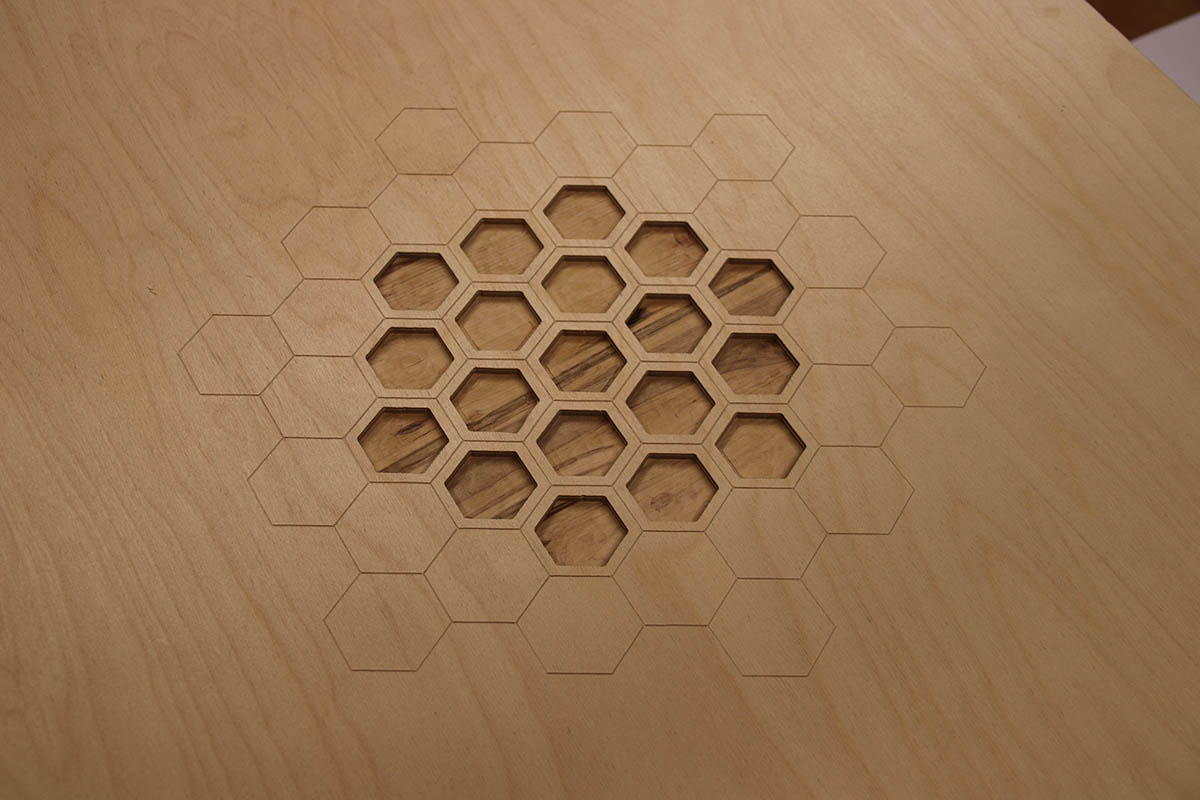
The honeycomb/hexagon pattern on the top
Something I still want to do is add inlays, but at the moment I just love the fact that you can see a darker, much more patterned wood layer in the hexagons. So I think of doing the inlays from plexiglass instead of wood. I would also like to add LED strips into the cuts I added under each plate, to get an illumination. But the table is even nice and finished without these details.
Files
Here you can download the files created during this week:
Fusion project file
SVG files used for cutting on the Shaper
STL files of the table
OpenScad file for the Joint I used
OpenScad file for the Hammer Tenon Joint I tested
SVG file for the Hammer Tenon Joint I tested
SVG file for the inlay test