Nineth Week
EMBEDDED PROGRAMMING
ASSESSESMENTS
| HAVE YOU : INDIVIDUAL | TASK COMPLETED |
|---|---|
| Read a microcontroller data sheet. Program your board to do something, with as many different programming languages and programming environments as possible. | YES |
GROUP PROJECT
| HAVE YOU : GROUP | TASK COMPLETED |
|---|---|
| Compare the performance and development workflows for other architectures | YES |
NEIL´S LESSON
Index
WEEK 9 : EMBEDDED PROGRAMMING
For this week´s assignment, the goal is to learn about Embedded Programming following this steps:
READING THE DATASHEET : HOW THE DATA HELP ME ?
1st.I have a bit experience reading datasheets but the Spark´s Fun tutorial about "How to read one" it´s really usefull for remember things :
I began by looking through the ATtiny44 microcontroller´s datasheet found at the homeworks page. There I found the necessary information about all. Some of the abbreviation were more easily understood than others but the experience learned me a lot.
A microcontroller is a small computer (SoC) on a single integrated circuit containing a processor core, memory, and programmable input/output peripherals. Program memory in the form of Ferroelectric RAM, NOR flash or OTP ROM is also often included on chip, as well as a typically small amount of RAM. Microcontrollers are designed for embedded applications, in contrast to the microprocessors used in personal computers or other general purpose applications consisting of various discrete chips.
AVR - ATtiny 44 Microcontroller
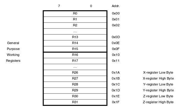
This is a Atmel 8 Bit low power micro controller combines 4KB ISP flash memory, 256-Byte EEPROM, 256B SRAM, 12 general purpose I/O lines, 32 general purpose working registers.
WHAT IS A REGISTER?
WHAT IS A REGISTER?
Registers are special storages elements in microcontrollers with 8 bits capacity and they look like this:

CHARACTERS OF REGISTERS COMPARED TO OTHER STORAGE ELEMENTS
CHARACTERS OF REGISTERS COMPARED TO OTHER STORAGE ELEMENTS
ATTINY 44 MEMORIES TYPES
ATTINY 44 MEMORIES TYPES
PROGRAMMING
PROGRAMMING
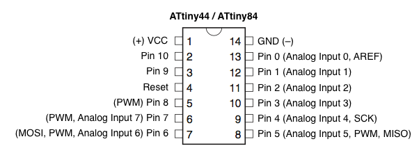
Program calls on each pin then sets it as an input or output, and either open or closed, so the datasheet show us the function of each pin.
LANGUAGES
WORKFLOWS - TOOLCHAINS (one saved my life at 4th week)
There are a few ways one can go about programming their board:
1. IDE Integrated Development Environment. A complete environment that does all the programming functions :
Atmel Studio
Arduino
2. Compiler Used to load programs (see languages section). Once you have a compiler you must to talk to the processor with host communication.
Compliling C code creates a hex file and microcontrollers read hex codes, not C.
GCC The GNU (an operating system) C compiler.
WinAVR- a C compiler for windows- Toolchain (GCC plus AVRlibC) for AVRs bundled for Windows.
3. Interpreter Uploads code to a chip. You must already have the hex file, so C code is not necessary.
AVRDUDE Also an ICE or In-circuit emulator without a graphical interface.
HOST COMMUNICATION
Host Communication allows to talk to the processor, once you have a compiler. In the case of the FabISP we are using a FTDI cable. FTDI goes from USB to logic - level serial.
BOOTLOADER
BOOTLOADER
A program that loads programs (the processor can self-program its own memory). A program that you load in through the ISP, then we can use the serial communication to program it.
QUESTIONS AND WHAT I WANT TO LEARN MORE
Obviously i have some questions but the thing what i want to learn more is about memories. Probably is good idea to use EPPROM for my final project, so this the next i want to learn more.
HOW DATASHEET HELP ME?
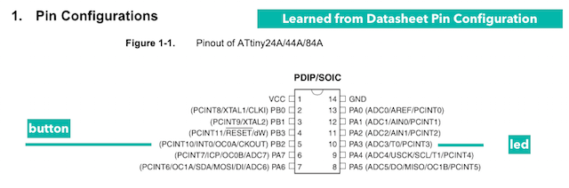
DESIGN : For understand better the Electronic design the dataSheet help to me for Know what pins i must to use for attach my electronics components as the button and the led and his correspondance with arduino Pin Out in my case 3 and 8.
PROGRAMMING : At this task, for advance with my programs i found some things interested relative to hardware. The datasheet show me the pins where i attached my electroncis components so i will declare this pins as an Input in the case of button and as an Output in the case of the led making them as a cosntant in the programs developed.
In my case this pins are 8 for the button and 3 for the led.
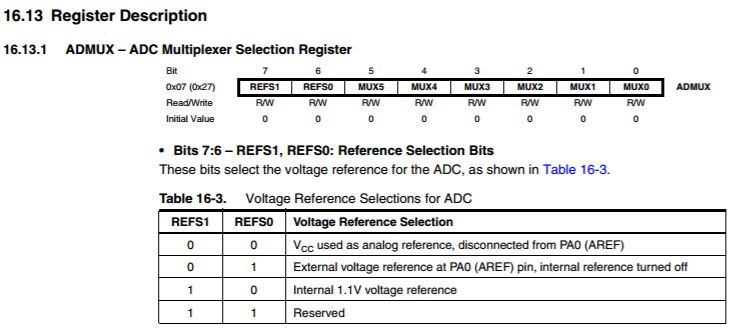
Another thing learned trought the datasheet was about read pin information and control all the features of the microcontroller must to write and read 8-bit instructions in the data registers so many features and functions need several data registers to operate.
So this the way for try to program with C. UNfortunely, my some attempts fighting with my terminal conflicts in the Electronics Design assignment dealy me all task so i want to try in the future, but know i can to configure how can to made a basic thing with this language.
This micro - Processors have short memory so they can ´t to do some task at the same time so teh idea is test basic programs and write my own based in them.
When i use the board for make the bootlaoder i would to use my FabISP is all is already for the momento to make this task.
The other Weeks where i used a Data was in assignment : Input Devices Assignment, Output Devices and Interface week. and Final Project Webpage.
CODE TIME
2nd. The second part of the assignment is programming the board designed at Week 5. I had differents problems with it so i decided begin with an enviroment that i know for feel a bit secure, this environment is :
ARDUINO : MY EXPERIENCES
If i have to described my experience with Arduino i want expressed with two pics (between both i´m living a funny process):
![]()
When i knew what i want to make with my things i bought one (2007), later i felt alone , during this years at the South of the Spain i couldn´t find someone with the same ideas, use micro-crontollers for creative things . I was studying Audiovisual Communication i had 2 subjects at "TELECO" University as Free Configuration Matters and engineers looked me like a crazy girl. I felt the same during my others careers because always selected "Heavy Subjects" as free just for my interest at the moment. As noOne understand me, finally, i decided to travel to USA for learn how interfacing with visuals programs for Performing Arts Purposes, after that, never feelt alone again. Actually teach about the tool in record time and i´m sure that my students become at happy arduino users. If you want to start making quick things now with Arduino you have a stable Hardware and Software Tool with powerfull Community. There in my opinion is the arduino´s growing success.
So i consider really helpfull their site, their learning page with usefull "References" and "Examples", of course, his forum. I found there a lot solutions for solves problems or simply learn more about sensors ;)
Actually Arduino have an on line editor :
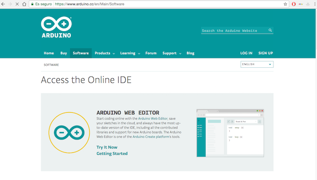
All for begin :
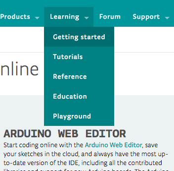
The best part for learn about everything :
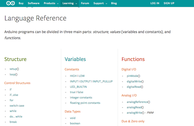
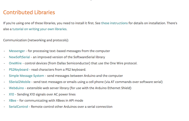
At libraries section is where we can learn about the library used in our examples for this week and for the rest of our lives :
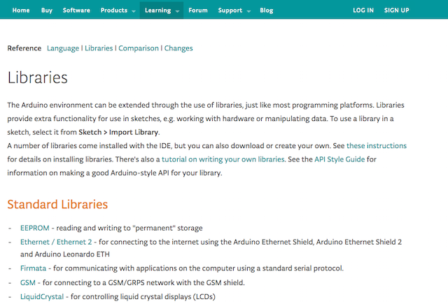
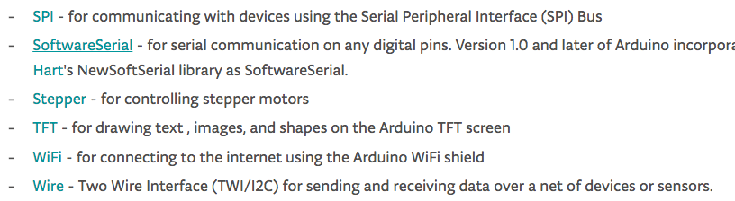
I have a lot experiences using contributed libraries made for good people interested in simply our lives, thanks librarie´s developers!!
MY HELLO BOARD PROGRAMS
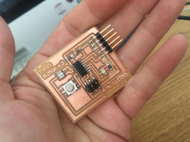
In order to programming my helloPilu board, I prepare some hardware and software as follows :
Unziped it puting the folder into : [documents] \ arduino \ hardware \ attiny \avr
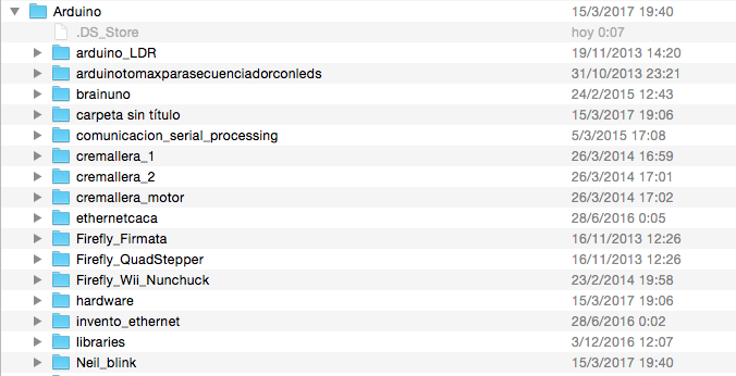
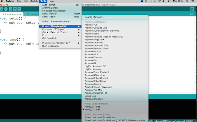
if successed, "ATtiny" will shows in arduino menu > Tools > board
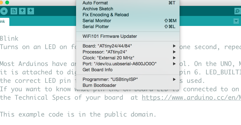
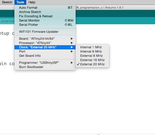
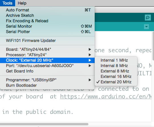
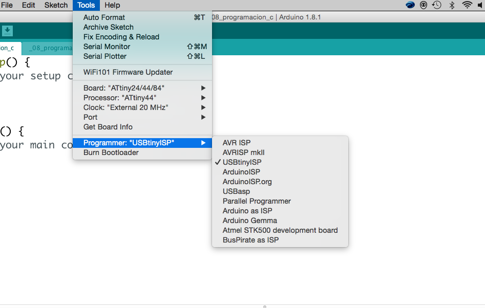
How the first toolchain for Avrdude installation works well for me i began with all conecting my boards to my computer and following this steps :
WEEK PROBLEMS
WEEK PROBLEMS
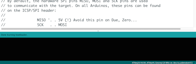
After this, if all works well i must to Burn the Bootloader of our hello button board and here began my problems.
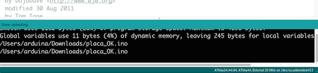
The console show me this message :
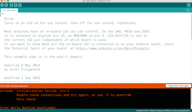
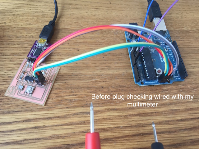
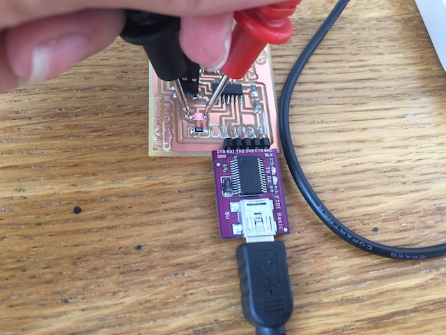
First, i decided to do was looking what mean the message in context looking at web forums where i found that i had a problem with my board as mostly people related probably will be a weld mistake. So i decided use the multimeter again for test continuity :
I didn´t use a common FTDI wire, i ´m using a FTDI mini USB adapter from Spark´s Fun which i used with commercials boards like lilyPad so i decided try differents test :
- First with voltage and ground connections between the adapter and the board
- Second between the boards and the rest of components without the adapter
I couldn´t find the error checking the design, everythings looks right, so for advance and how i have a bit experience with arduino IDE i was modifying the basic sketches from our instructor Epifanio for practice things, connecting a button and led to an Arduino board with a breadboard. I was commenting and changing values, practicing serial communication.
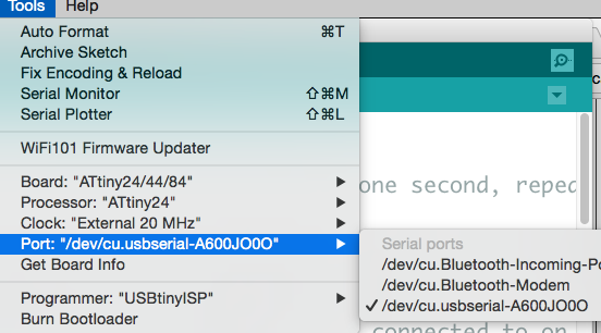
For try more things and solve the bootloader problems i was connecting more boards like lilyPad, FabISP, Arduino, brian´s...my system find all but not all are listed at my Terminal window, so this explain that something is causing a conflict because is really strange that arduino sometimes show the serial port and sometimes not.
I Uninstall and Install Arduino IDE and drivers some times without good results. So i was searching at stackoverFlow page and other similars with the idea to find someone with the same problems.
I explained my problem to my Guru at the tuesday review but she cannot understand things happen like me because never find the same error.
My instructor was looking solutions for me again , i think he is working a lot for help me to solve all my computer system conflicts.Thank always Epi! You rocks!
Every week i have a lot problems with my computer versions of things so this process learned me a lot about new lines command for remove things or deleted conflicted libraries, or simply apply new methods for advance.
The process for people without like for "to fight" can be frustrated but i can lost days reading solutions or case similars....I miss a bit more time for to study better my problems but finally i´going solve and gained a lot of things during the way.
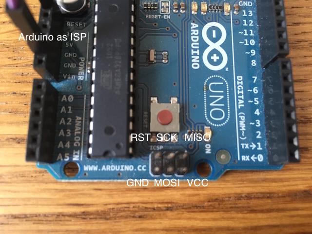
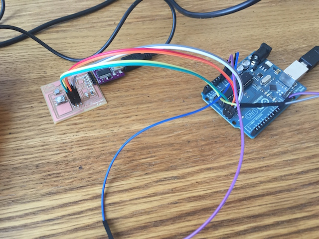
THINGS I LEARNED : USING AN ARDUINO AS AN ISP
In order to advance i used an Arduino as an ISP : Why use an Arduino as ISP?
First a i want to comment is my instructor never use an Arduino as ISP, so i want to explain this as better as possible
Here is a tutorial for begin :
In order to use the arduino as FabISP it needs to be programmed so at their official site, i git more references about the process :
However I had access to plenty of arduinos and they easily can be programmed via USB. The reason, you can program an arduino without an external programmer is because they comes with a preinstalled bootloader. Programming the Arduino for the job :
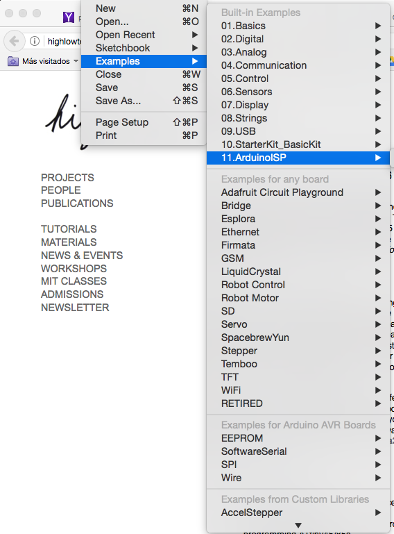
The Arduino IDE have an official sketch (arduino program) for using the arduino as an ISP, it comes with the arduino installer as one of their: File->Examples called ArduinoISP.
I want to use it to pass along our own code, the FabISP firmware to our card. This is why the official instructions are only useful until step 5. After that the rest are your research.
After we have uploaded the modified ArudinoISP sketch to our arduino we had to add a 10 uF capacitor between reset and ground. Like this:
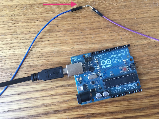
It has to do with the special way we will be using the arduino after we programmed it with the ArduinoISP sketch. Now we want to send code through it, not reprogram it. If we leave out the capacitor the arduino will interpret us sending code to it as an attempting to reprogram it and do an automatic reset, sending the code that we inteded for our FabISP to the arduino bootloader instead. If we include the capacitor, it absorbs the reset pulse and lets us send the code through the arduino to the FabISP card being programmed instead.
What is a bootloader? "The bootloader is basically a .hex file that runs when you turn on the board. It is very similar to the BIOS that runs on your PC. It does two things. First, it looks around to see if the computer is trying to program it. If it is, it grabs the program from the computer and uploads it into the ICs memory (in a specific location so as not to overwrite the bootloader). That is why when you try to upload code, the Arduino IDE resets the chip.
This basically turns the IC off and back on again so the bootloader can start running again. If the computer isn’t trying to upload code, it tells the chip to run the code that’s already stored in memory. Once it locates and runs your program, the Arduino continuously loops through the program and does so as long as the board has power."
Finally i can made the bootloader to the helloButton and the rest of code modified for the assignment.
PROGRAMING THE BOARD II
I used for practice some codes suggested by our instructor where every student can practice simple things and advance in order to learn, so i decided rewrite some of this codes before develope my own.
1st BASIC EXERCISE : The first exercise used was the basic blink modified by different people during the last years so this is the example:
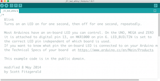
For test with my board just changed the number where i have attached the led in my case the digital Pin3 and change the time for make the blink with the delay at an half of second so here is the code rewrited :
/*
Blink Test for Hello Pilu Board v3 based in the code write by Tom Igoe and modified by others:
modified 8 May 2014
by Scott Fitzgerald
modified 2 Sep 2016
by Arturo Guadalupi
modified 8 Sep 2016
by Colby Newman
This example code is in the public domain.
HOW IT WORKS ? Turns on an LED on for an half second, then off for an half second, repeatedly.
*/
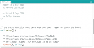
// the setup function runs once when you press reset or power the board
void setup() {
// https://www.arduino.cc/en/Reference/PinMode
// https://www.arduino.cc/en/Reference/Constants
// initialize digital pin LED_BUILTIN as an output.
pinMode(3, OUTPUT);
}
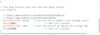
// the loop function runs over and over again forever
void loop() {
// https://www.arduino.cc/en/Reference/DigitalWrite
// https://www.arduino.cc/en/Reference/Delay
digitalWrite(3, HIGH); // turn the LED on (HIGH is the voltage level)
delay(500);
digitalWrite(3, LOW); // turn the LED off by making the voltage LOW
delay(500);
}
Embbed Programing : Button + Led I from Pilu Caballero on Vimeo.
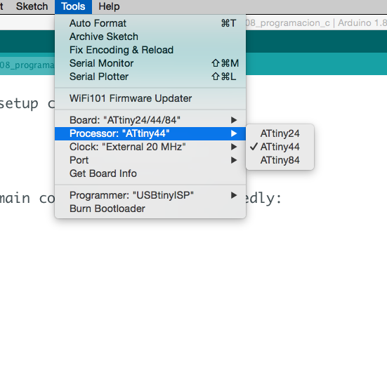
2nd BASIC EXERCISES : The next exercise i used was the basic example for use an input (the button) interacting with an output (the led). the idea to rewrite the exercise is practice the use of conditionals for make the functions possible: As you can see at the code i declare the state of the button before at Setup()
const int pinBoton = 8;      // Pin whre is attached my button
const int pinLed =  3;      // Pin where is attached my led
int estadoBoton = 0;       // variable for reading the pushbutton status

void setup() {
  pinMode(pinLed, OUTPUT);
  pinMode(pinBoton, INPUT);
}

void loop() {
  estadoBoton = digitalRead(pinBoton);
  if (estadoBoton == LOW) {
    digitalWrite(pinLed, LOW);
  } else {
    digitalWrite(pinLed, HIGH);
  }
}
Embbed Programming : Button + Led II from Pilu Caballero on Vimeo.
3rd BASIC EXERCISE : The last exercise i was practicing is another modified code from Tom Igoe in 2011 but was created at the early 2005
by DojoDave
With this code i just was playing with the time for turn the led on and changing button state values :
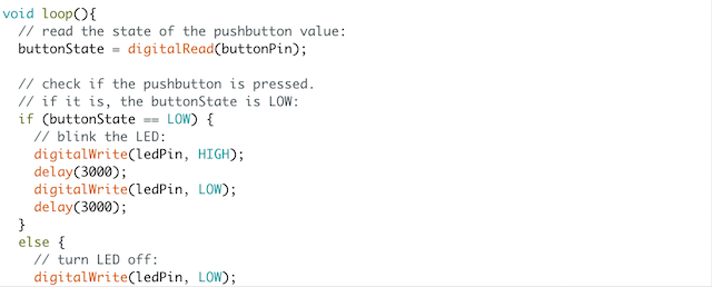
 /* created 2005
 by DojoDave
 modified 30 Aug 2011
 by Tom Igoe

 This example code is in the public domain.

 http://www.arduino.cc/en/Tutorial/Button
 Modified by me for test how my hello button board works
 */


const int boton = 8;     // the number of the pushbutton pin
const int led =  3;      // the number of the LED pin

// variables will change:
int estado = 1;         // variable for reading the pushbutton status


void setup() {

  // initialize the LED pin as an output:
  pinMode(led, OUTPUT);

  // initialize the pushbutton pin as an input_pullup:
  pinMode(boton, INPUT_PULLUP);
}

void loop() {
  // https://www.arduino.cc/en/Reference/DigitalRead
  // read the state of the pushbutton value:
  estado = digitalRead(boton);

  // https://www.arduino.cc/en/Reference/If
  // https://www.arduino.cc/en/Reference/Else
  // check if the pushbutton is pressed. if it is, the buttonState is ON:

  if (estado== LOW) {

    // https://www.arduino.cc/en/Reference/DigitalWrite
    // turn LED oFF:

    digitalWrite(led, HIGH);
    delay(3000);
    }
    else {
    // turn LED off:

    digitalWrite(led, LOW);
    delay(3000);
  }
}
Button Codes from Pilu Caballero on Vimeo.
MY OWN CODE : Thinking in my "Final Project" i decided practice some things useful for the future. For this part, the datasheet about the Attiny 44 help me so much. for example, the Tiny has a limited memory for this reason i decide make a program using the monitor serial for send message trought this and see how the sensors is working.
const int led = 3;      // constante donde está el led

void setup() {
mySerial.begin(115200); // velocidad de baudrate para el Attiny 44
pinMode(led, OUTPUT);

}

void loop() {
  byte activar;
  if (mySerial.available()) {
    activar = mySerial.read();
   if (activar == '1') {
   digitalWrite(led, HIGH);
   mySerial.println("encendido");
   }
    else if (activar == '2'){
    digitalWrite(led, LOW);
    mySerial.println("apagado");
 }

    else if (activar == '3'){

	  digitalWrite(led, HIGH);
	  delay(1000);
	  digitalWrite(led, LOW);
	  delay(1000);
	  digitalWrite(led, HIGH);
	  delay(1000);
	  digitalWrite(led, LOW);
	  delay(1000);
	  mySerial.println("parpadea");

 }
  else {
    mySerial.println("1 activar y 2 apagar.");
  }
  }
}
const int  boton = 8;   // elegir el pin 8 como botón
const int led = 3;      // elegir el pin 3 de led
int contador = 0;   // contador de botón
int estado = 0;         //
int finEstado = 0;     //

void setup() {
   pinMode(boton, INPUT_PULLUP); // elegir el botón como input pullup
   pinMode(led, OUTPUT); // elegir el led como salida
   Serial.begin(115200); // velocidad del puerto serie
}

void loop() {
  estado = digitalRead(boton); // enlaza el stado del botón con la lectura del pin del botón
  if (estado != finEstado) { //
  if (estado == LOW) {
   contador++;
  if (contador % 3 -1 == 0)
  Serial.println("hola estoy vivo");
  if (contador % 3 -2 == 0)
  Serial.println("esto son pruebas");
  if (contador % 3 == 0)
  Serial.println("tu placa se comunica muy bien conmigo");
       }
    delay(50);
  }

  finEstado = estado;
  if (contador % 3 == 0) {
     digitalWrite(led, HIGH);
  } else {
     digitalWrite(led, LOW);
  }
}
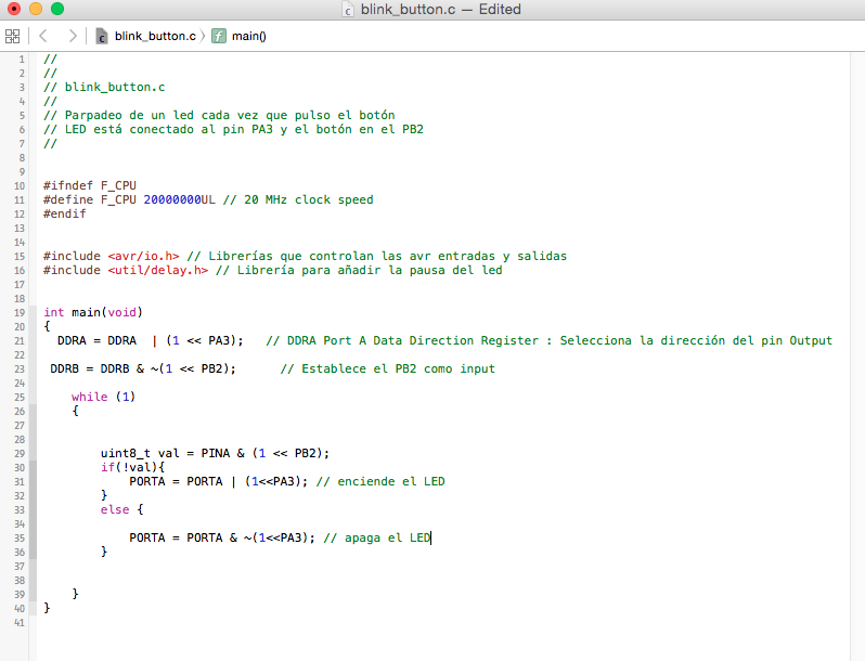
As i had many problems with the Fab ISP attempt with other arquitectures or languages was a bit difficult but i made a basic example for blink my led with C
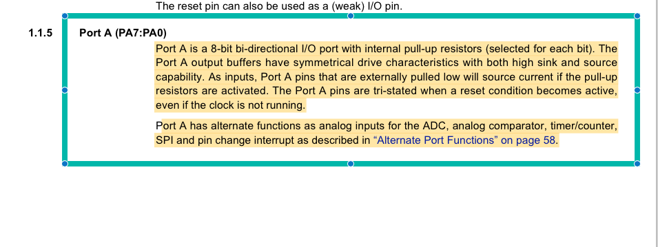
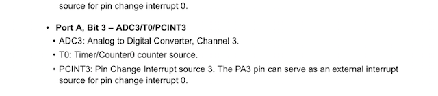
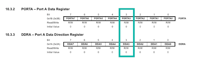
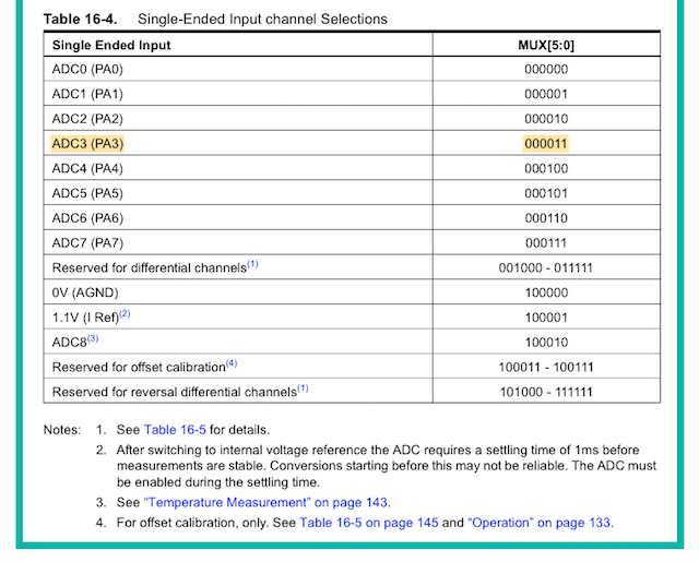
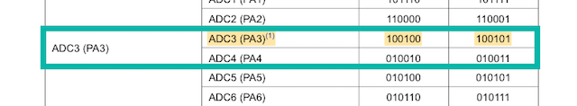
I had to find how to asign pin3 PA3 as an output and how to set it to high and low to turn the led on and off. In page 3 it describes the Port A as a 8-bit bidirectional I/O port. In page 66, 10.3.2 and 10.3.3 it describes how to set up PA3 direction and content. So I need to specify in binary the register DDRA to set PA3 to be output and alternate register PORTA to set PA3 to high and low values.
#include
#include


int main (void)
{
  // set PA3 to be output
	DDRA = 0b10000000;
  while (1) {

    // set PA3 high
    PORTA = 0b10000000;
    _delay_ms(500);
    // set PA3 low
    PORTA = 0b00000000;
    _delay_ms(500);

  }
  return 1;
}
Other C Program that i made was this :
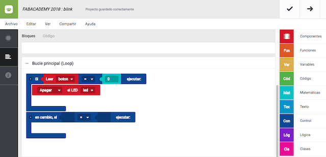
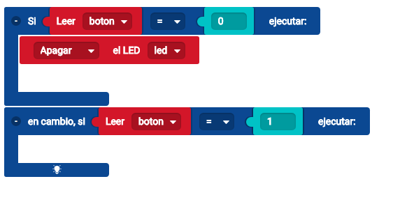
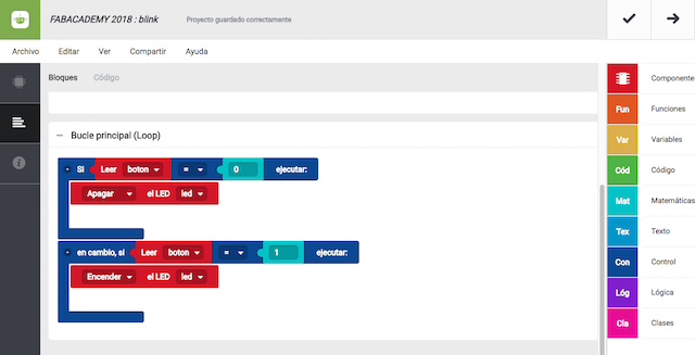
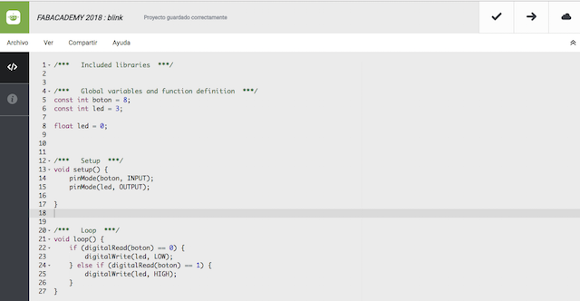
For finish with the assignment i decided to try in a languages that my students use a lot : BITBLOQ is a friendly application developed by BQ for use with their educational tools so this was the program results :
/***   Included libraries  ***/


/***   Global variables and function definition  ***/
const int boton = 8;
const int led = 3;

float led = 0;


/***   Setup  ***/
void setup() {
    pinMode(boton, INPUT);
    pinMode(led, OUTPUT);

}


/***   Loop  ***/
void loop() {
    if (digitalRead(boton) == 0) {
        digitalWrite(led, LOW);
    } else if (digitalRead(boton) == 1) {
        digitalWrite(led, HIGH);
    }
}
WEEK SOLUTIONS FOR MY FAB ISP
WEEK SOLUTIONS FOR MY FAB ISP
Solutions came as an unexpected way 2 weeks later when i was preparing the enviroment for MTM assignments. As i described at the above, sometimes the Arduino IDE show the serial port sometimes not, right? when i connected the RS 485 Wire for the first time, i shaw it at my computer system info, but when a i list ports for to Know his name, my system didn´t.
Searching during 2 days, more than 30h spent in this task, finally and repeating all process with my instructor. We found a solutions at the DX22 Driver Installation Manual
The DX22 Driver is installed on my laptop from ong time ago because is a driver for my Printer. Reading inside the manual we found that the driver have a helper that sometimes cause a conflict with the FTDI Driver. For try we use the command lines inside the manual and all works fine.
So with my FabISP Programed without problems any board during my Academy will be burned with it!! I´m happ for that!
WEEK FILES
WEEK CONCLUSIONS
During this week i had a lot problems with my FabISP too but was a good idea advance with code in order to finish the assignment in time. Now i had a new tutorial about the Attiny 44. The datasheet help me for recognize analog or digital pins. Solved the driver conflict with the D2XX my system was ready for program en any time. If my mistakes or system conflicts had been less, probably i should to practice C programming but was imposible attempt more with my job.
For this new cycle, we must to try to programming with other arquitectures, so we decided to use our Raspberries Pi3 for make the task. The idea is use Python for make basic exercises where elecronics components meets with the Raspberry.
I developed a web page for post our conclusions and made the code programs for the first exercises so if you want to know more about it, please ckeck our group page :