Fourth Week
COMPUTER CONTROLLED CUTTING
ASSESSESMENTS
| HAVE YOU : LASER MACHINE | TASK COMPLETED |
|---|---|
| Explained what you did at Group Assignment | YES |
| Explained how you Parametrically Designed your files | YES |
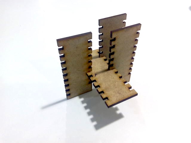
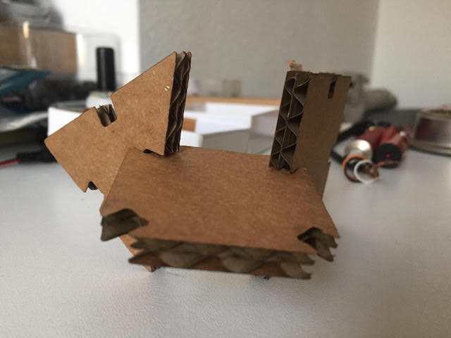
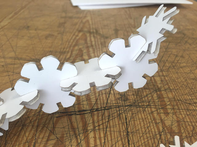
| Shown how you made your Press-Fit Kit | YES |
| Included your original design files photos of your finished project | YES |
NEIL´S LESSON
Index
- WEEK TASK : For the week´s assignment the goal is : to learn about Computer Controlled Cutting making practices with differents tools and techniques as a group and every one by himself.
- Files
- My Week Problems Solved
- Things I Learned
- My Week Conclusions
MY LASER GROUP PRACTICES
1st. For this week , the first part of our assignments was to practice in group, cuts and engraves types with two differents machines in any material admited it for learn about some important concepts in digital fabrication asthe Kerf. The machines we used are :
You can know the technicals details showing our fablab´s inventory.
With this practice we learned about fabmodules too for prepare the files and sent them to the machine in correct way. Was a great experience, fabmodules symply a lot the task at the vinyl cutter machine .
KERF: WHAT IS IT?
Probably the one of the most important concept about fabrication in the week i gained because never use Laser Machines before. Why is important? When using subtractive fabrication technologies you must to pay attention to cutting kerf, the width of material that is removed by the laser cutting process, this quantity always will to depend on the laser machine model and the material so measuring the kerf is always neccesary. As a group task we experimented with different cutting parameters, materials and measured the cutting kerf of Fab Lab Madrid CEU laser cutters, results of this task are described in this page
A schematic drawing of a saw blade looking head-on: the divergence between the teeth that protrude left-and-right is the kerf, it defines the width of the saw cut. (Another essential word for my Glossary )

After we cleared basic things, my classmate Alvaro designed a basic template with differents forms or sizes for test things with the goal to calculate the kerf and practice this necessary item for cut and engrave with success any material´s used.
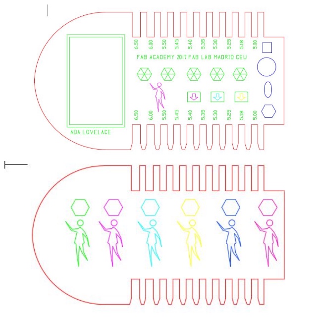
Each layer was for make cuts or fills different engraving or for place in order of the machine :
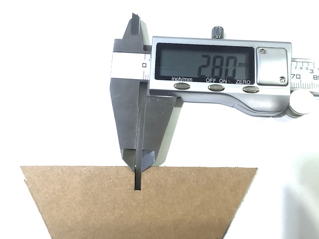
Our cardboard have 5mm so we test the different types of engraving stuffing and cutting.
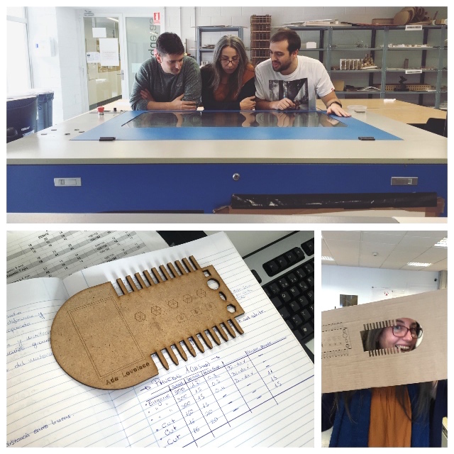
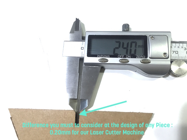
Finally I used the calliper tool, always recommended for be precise:
Here begin our Week Problems the desig made by fabmate Alvaro is non parametric so i decided to solve this designing new one tester.
WHAT I MADE FOR THE GROUP
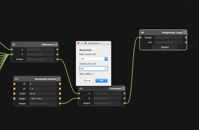
As i Commented above, my fabmate miss to design the test parametric so i decided to use Antimony for design a basic cardboard for send to Javi who will to cut at Limerick´s Fablab where he work.
This was the process that i followed for design with Antimony :
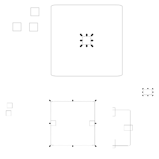
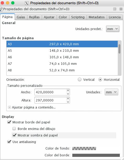
Exporting image as a .png later. I used it at Inkscape for vectorize and Cut at the Laser Machine with two sizes of Cardboards :


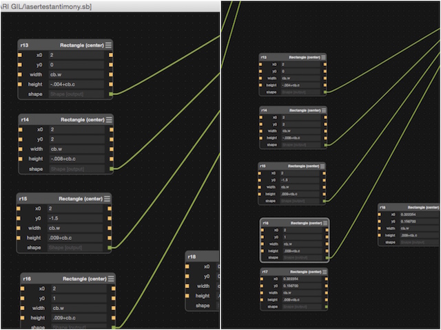
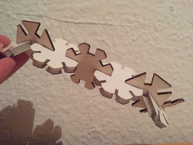
For finish this part, my fabmate Javier Burón and as he say at their website, he adjust some things for cut at FabLab Limerick where he work actually. He managed to measure the cutting kerf on Fab Lab Limerick's Speedy 400 but only on the corrugated cardboard that it was used for his press fit design. Since then he have had a look at some gauge designs for their fab lab users so they can measure the kerf more easily.
On the left side incrementing the width of the slot by 0,01mm from bottom to top and or the right side decreasing the width by 0,01mm. This would allow us to measure the kerf of the laser cutter and the right parameters for a snug press fit joint.
I made some things more for the group as a document about our tester´s processes with the machines, wrappers about speeds and power for each one, materials, other tools used. Basically all settings for our laser machines.
Also i was making all photos and vídeos for document our webpage, look some pics for the Kerf´s template design and of course, i was working with the machines learning about all processes, preparing the files there, adjusting the main settings for calculate the file before sent to the laser machine.
I learned a lot about settings for different materials, the main are :
We develope a web page also which have more specific details. There we explaines about the problems and goals obtained and conclusions with the experience. For me was fantastic because never use one. I love them, they learned me a lot, definiteviley i will to add this technology to my final project.
If you want to know more about our process practices here it´s the link :
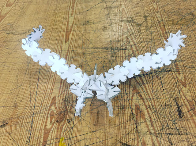
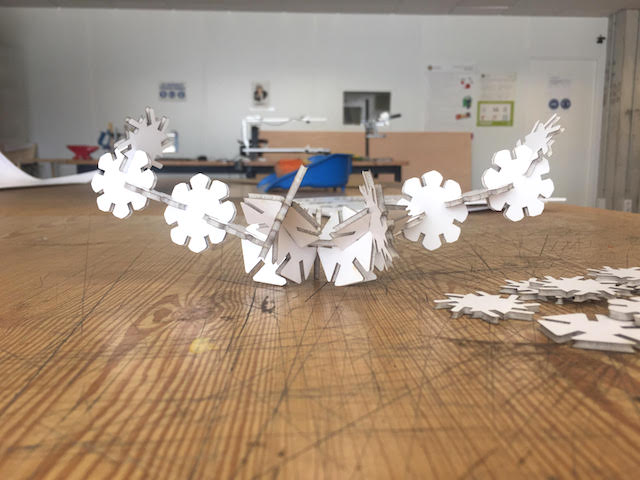
Laser Machine III: My Press Fit Construction Kit. Processes
How never design parametrics, i was practicing whit differents tools like :
INKSCAPE
Sometimes, i coded generative patterns for make visual clips with Processing and Max/Msp-Jitter and i was searching same results at inkscape, so , i design some patterns while i had thinking about the game.
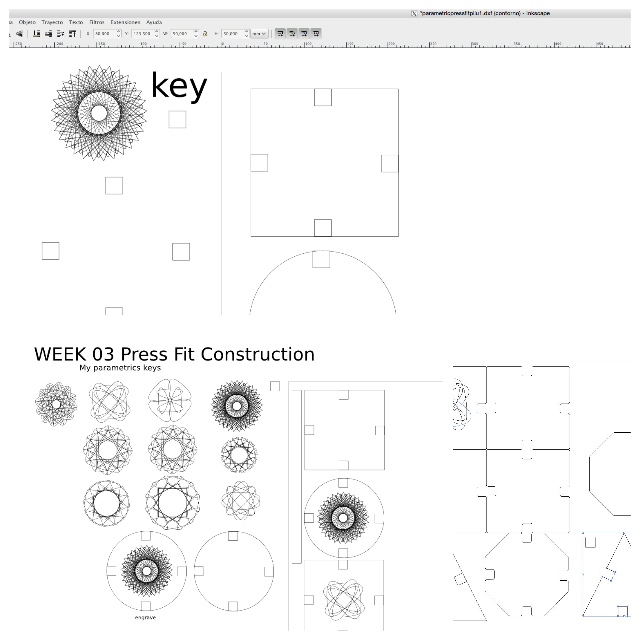
For practice with more tools, after, i saved my file as svg.format and sent it to:
ILLUSTRATOR
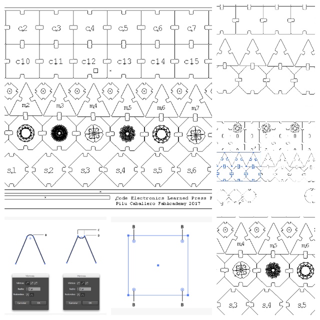
Code Learned Game Press Fit Construction Kit
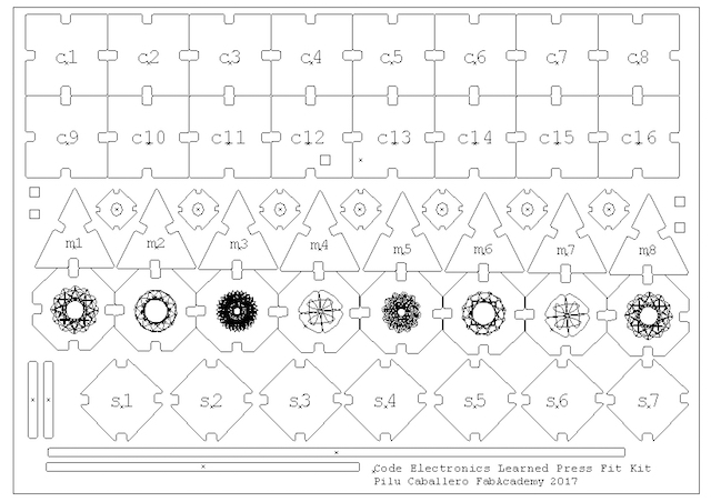
A game for practice codeMind and basics about Electronic Circuits
RULES
SURE I USED some day in a lesson with my students playing but for the moment you must to wait to the pics. Sorry!
WEEK PROBLEMS
1. After test mades at Laser Machine, i had a problem when exported my file as SVG to Illustrator, the size of kerf changed :
2. When my guru said me that Clones Tool from inkscape dissapear soon and my design will to turn in a " non parametric design", i can´t believe... so i decided to try another things with real parametric tool like :
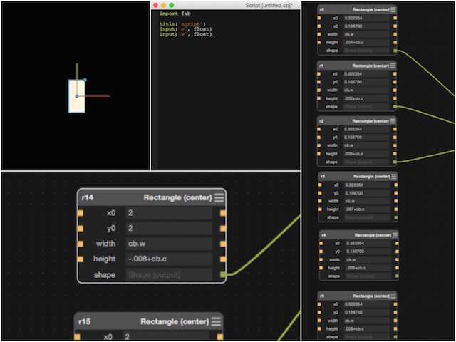
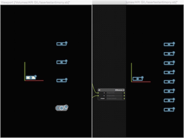
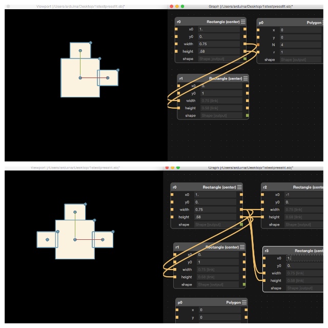
1. I used the basics for make a rectangle at the center plane :

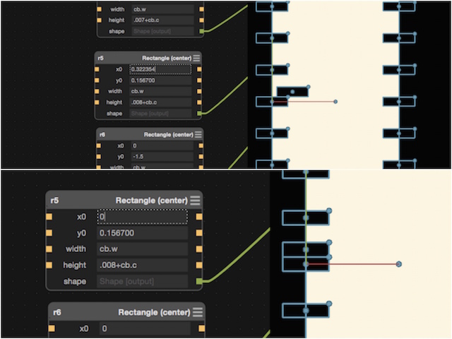
2. Copied and paste rectangles center and later allign with x, y coordinates :
3. Maths : Parametric Differences
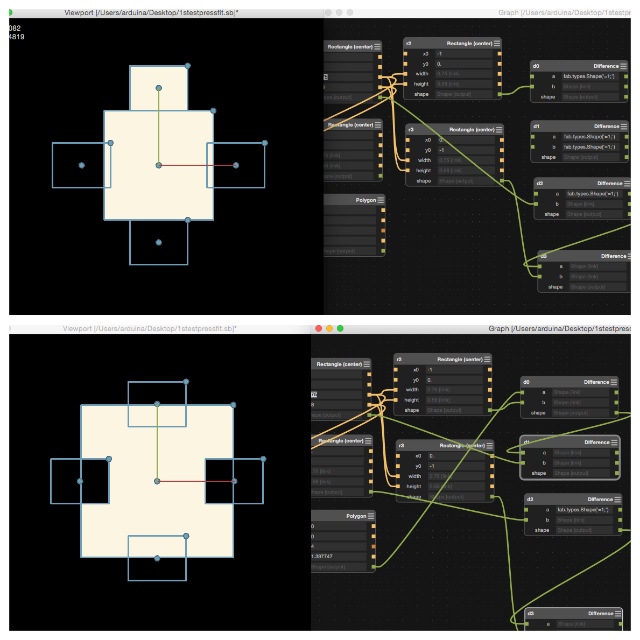
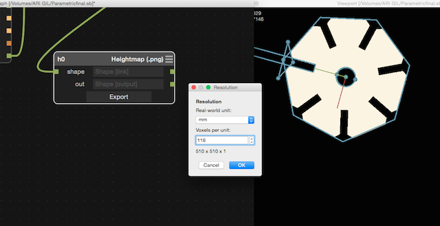
Antimony is powerfull, the process and the GUI user interface was more intuitive. I designed parametrics parts for a possible "Press Fit" spending bit time. With Antimony i can to exporte each model for work with meshes or heightmap quickly. I exported each object like a heightmap .png :
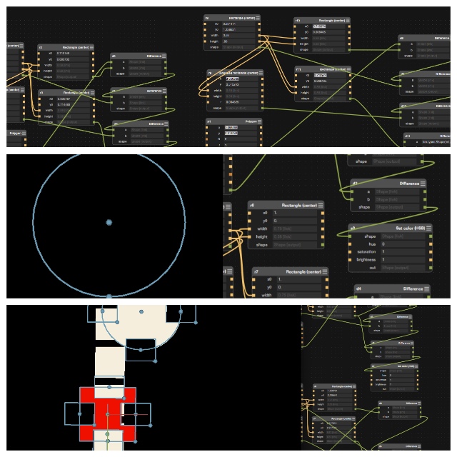
So i decided practice more how learn to make Chamfers so this was i made
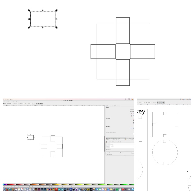
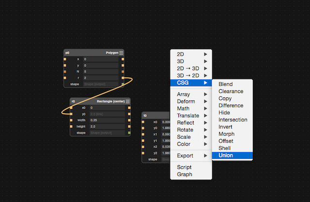
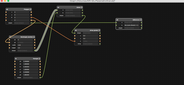
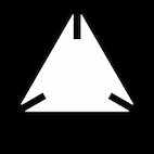
1.Draw a 2D Polygon first :
2. Put another geometryBox and the union script :
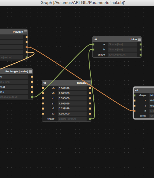
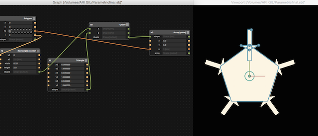
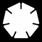
3. I made an array polar for intersections :
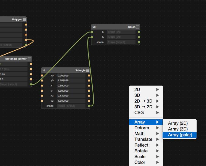
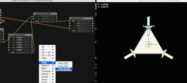
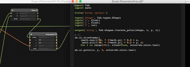
You can see at the script how my design is now iterative :
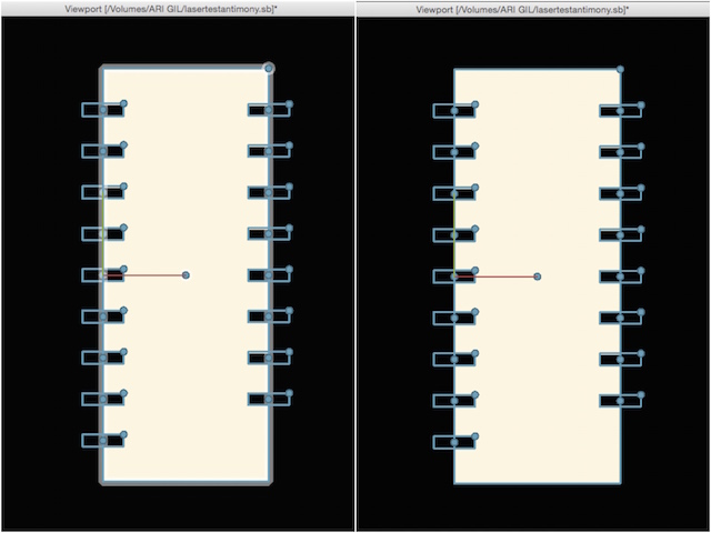
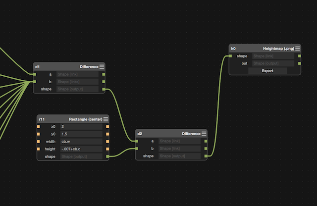
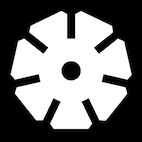
4. For finish with the design, i made the difference :
5. For export the design, i choosed Heightmap :
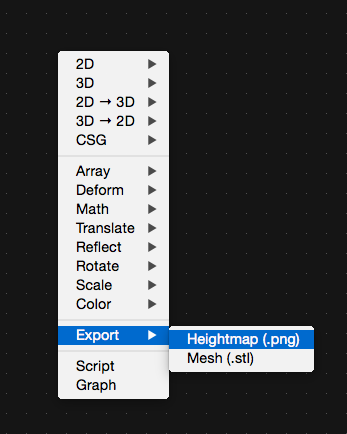
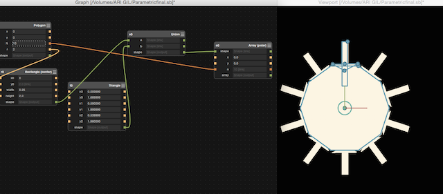
6. As the design is parametric, you can choose the surface just adjusting bit things :
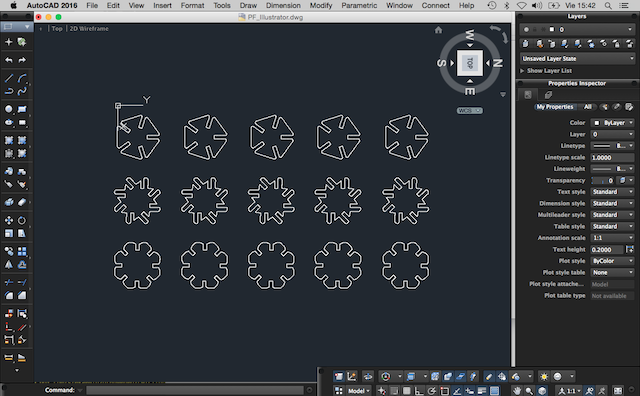
So i decided to export some models for made the same process made at Illustrator but this time at AUTOCAD.
LASER CUTTING TIME : The results
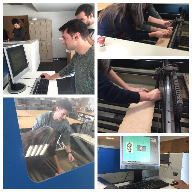
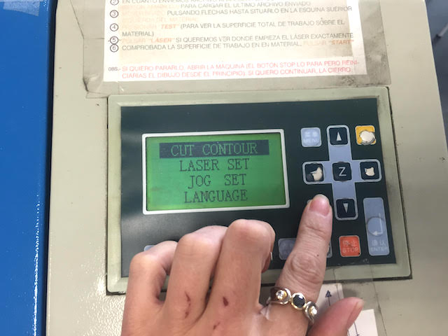
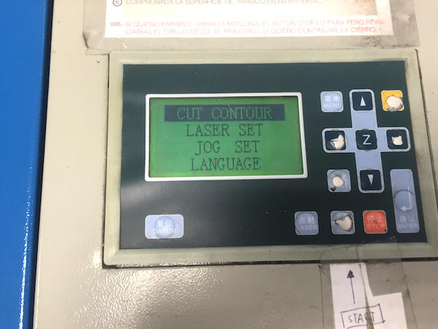
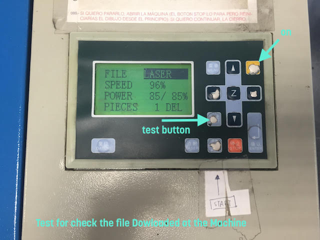
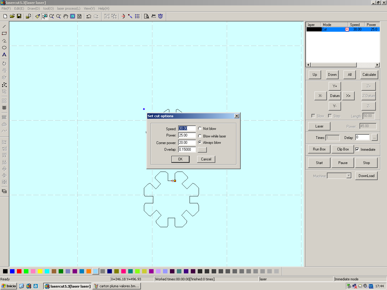
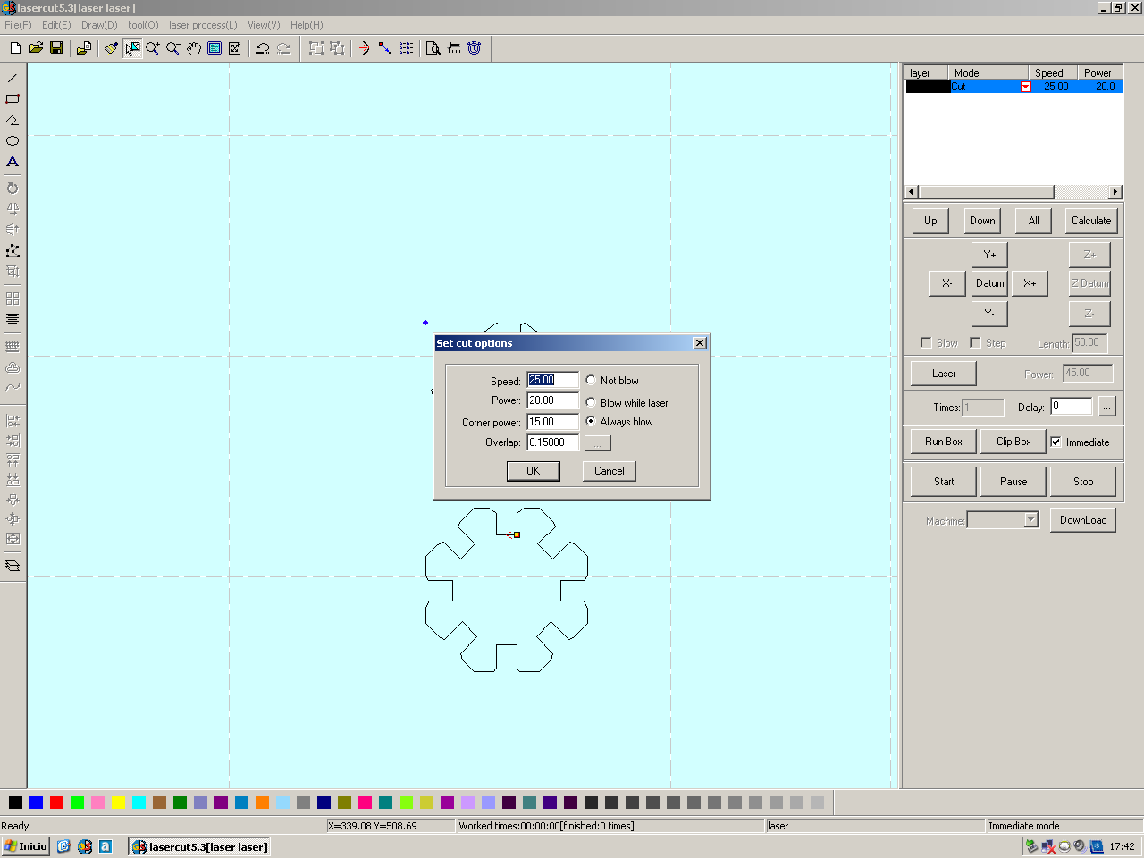
First i made was prepare my file at the computer of machine setting the parameters for cut :
At the pic below you can see the parameters used:
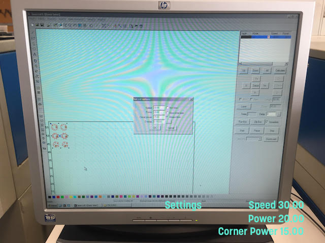
I made a contour test for be sure where the laser will to begin :
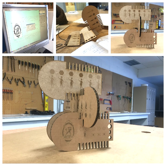
This was teh results for the first attempts :
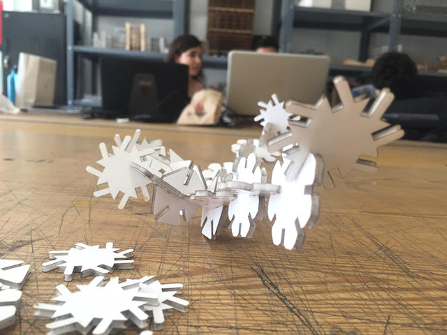
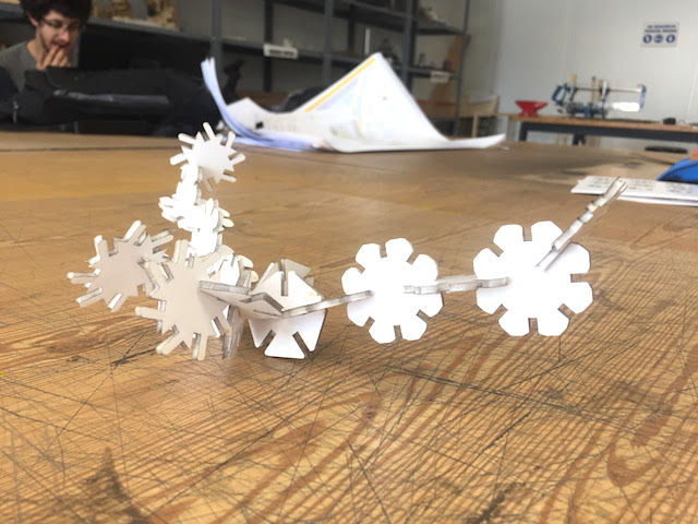
With the toolpath clear i decided to made the last attempt :
This is my hero pic :
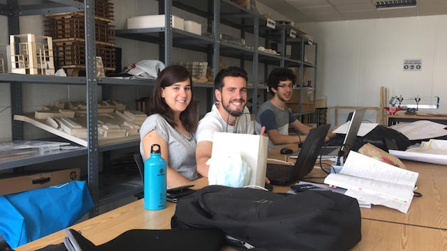
My new Laser friends, the guys who working here:
RESEARCHING EXTRAS
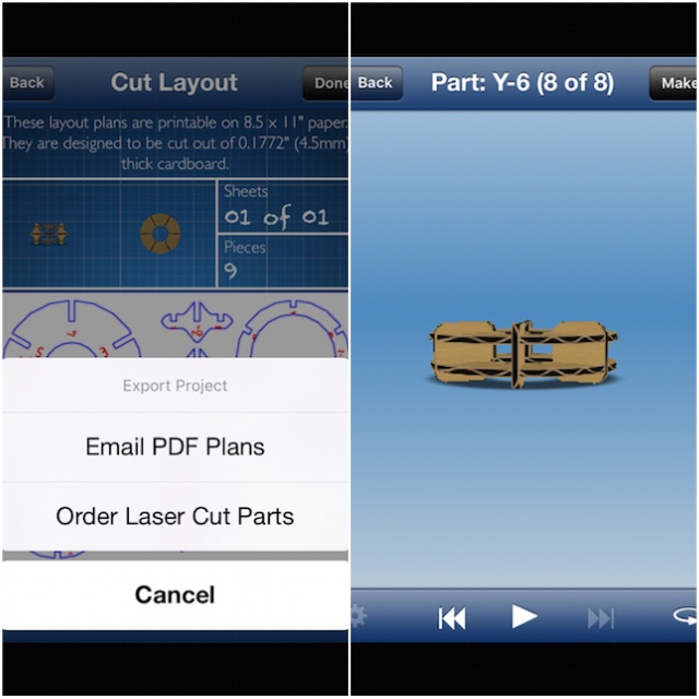
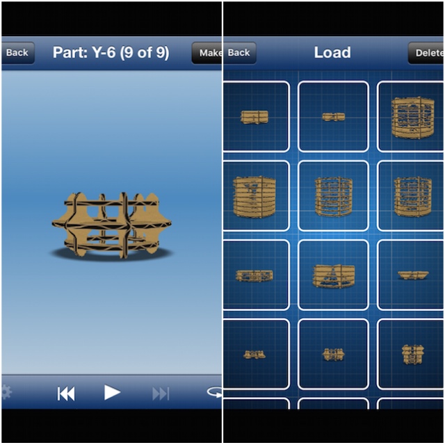
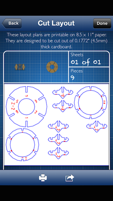
The last thing i was trying was use the 123DMake mobile device App for generate differents possibles patterns. A friendly use with a lot of limitations but fun for explore the possibilities, export files and redesign them or for introduce in on interlockings.

ASSESSESMENTS
VINYL CUTTER MACHINE PRACTICE
| HAVE YOU: VINYL CUTTER MACHINE | TASK COMPLETED |
|---|---|
| Explained how you drew your files | YES |
| Shown how you made your vinyl project | YES |
| Included your design files and photos of your finished project | YES |
| Included your original design files photos of your finished project | YES |
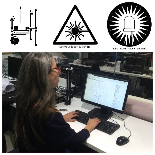
- I used Inkscape for continue practicing the last assignments and composed some basic stickers, the workflow was :
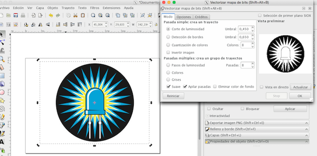
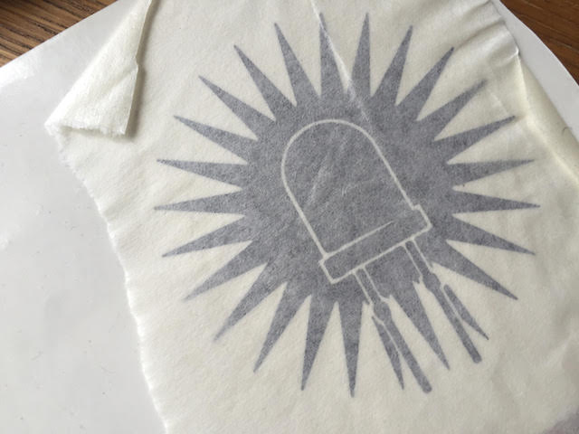
1. I import a file found on internet, a led image from Adafruit that i use for add some letters later to the design:
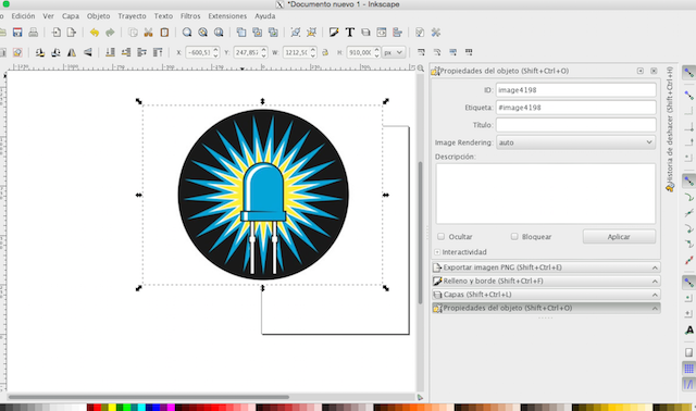
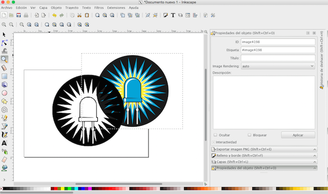
2. Selected the design and i vectorized it with bitmap Tool :
3. Later deleted the image import first :
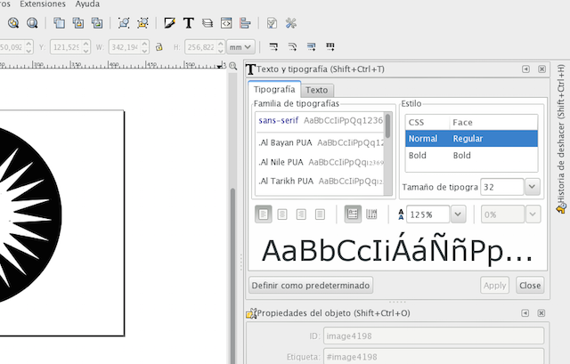
4. Finally i added a basic line of text :
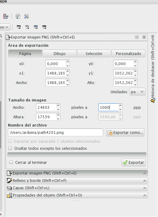
5. The last step was export the file such as .png adjusting resolution to 1000 dpi :
The inkscape version i had installed on my laptop sometimes do vectors right sometimes no. This made me delay on symple task but for RESOLVE, i was researching and i discovered that maybe it´s libraries missed. So i decided uninstall and install again while used the fablab´s computer for export my files as a 999,99 dpi .png.
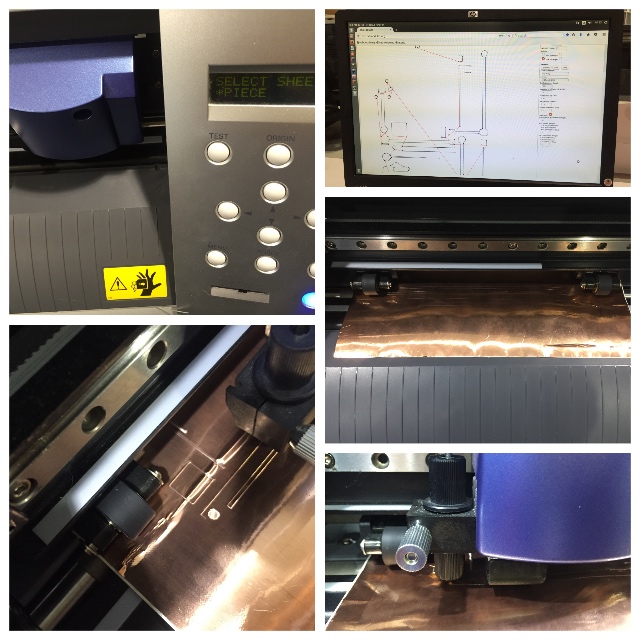
- After basic problems resolved, i made testers with speed and power for learn about materials response :
- At the computer : See the pic below, me calculating the file with fabmodules before to send it to Vinyl Cutter machine.
1. Fab modules: I opened the server and execute the comand line at terminal writing :
./fab_modules
2. Selected the Machine used in our fablab > Roland Vinyl Output
3. Selected file format > .png
4. Selected materials for Cut > Vinyl 80g
5. Sent my first sticker to the Vinyl Cutter Machine.
6. Later, i adjusted the roll to the vinyl cutter machine and set the machine.
For finish, i repeated the same with others designs but with vinyl´s pieces thinking in the use of small parts for differents materials.
Here are the settings for my results without problems :
Vinyl Cutter Machine Settings
| Vinyl Cutter Machine Model : | Material | Thickness | Speed | Cut |
|---|---|---|---|---|
| Vinyl Diode | Pink Vinyl Roll | 5mm | 100 | Yes |
| Vinyl Kite Sticker | Black Vinyl Roll | 2.50mm | 100 | Yes |
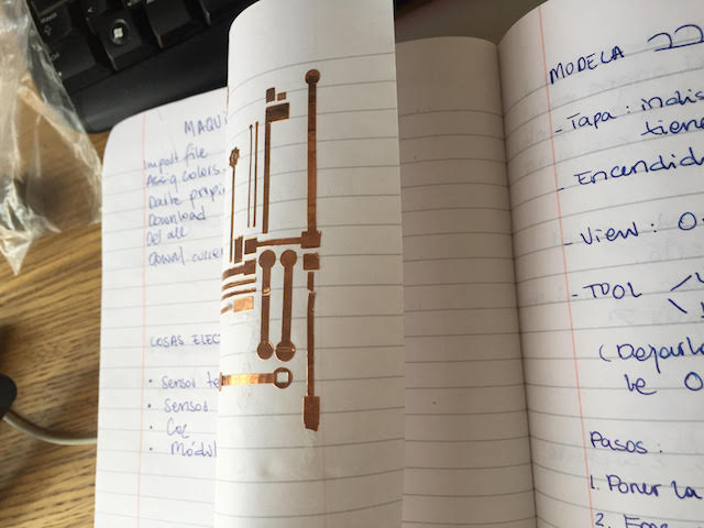
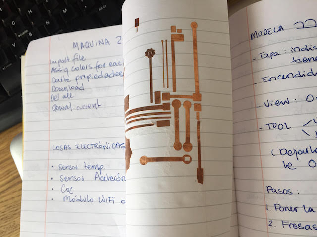
| Copper Tape Circuit | Copper Tape | 3.60mm | 40 | Yes |
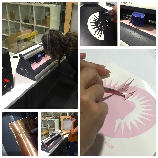
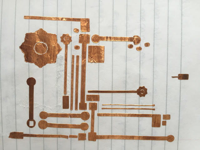
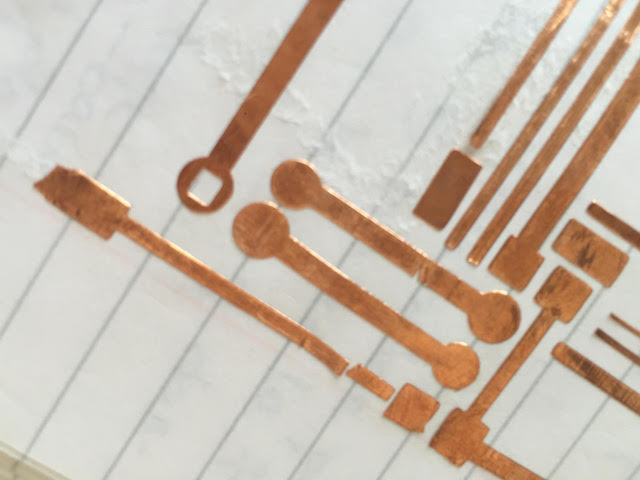
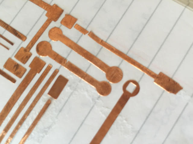
I´m really interested in Soft Circuits or make flexibles assembled for electronics for my final project, so i was trying sizes traces with copper tape .
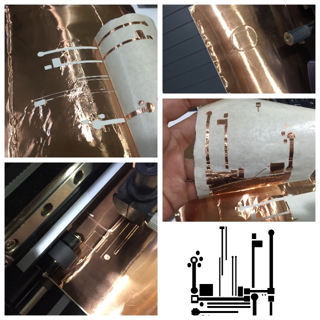
Testers with Copper Tape learned me a lot about the speed and force for cut correctly the traces on this material : Low speed and Power are better . First attends, the knife up the smaller traces and this cause bad results and usually can break another traces.

I want to practice more and hope i deserve time for try real electronics designs .