Individual assignment
My In-circuit programmer
My first attempt: FabTinyISP
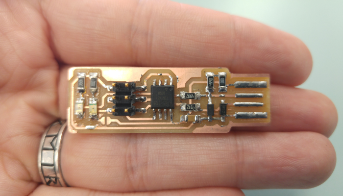
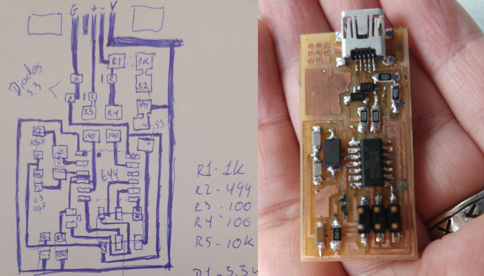
My first attempt wound up looking like this. All the pieces are in the right place, diodes face the right way and I am fairly happy with it despite the shoddy soldering in places. We discovered that we've had our iron set way too hot! We had it set to over 400°C, which evaporates the flux much faster than it ought to. This was something we discovered after we were done with most of our work.
I used the technique Neal described, where you place a small blob of lead on the board by one pin to which you "fasten" the component while you solder the other joints properly, then return to the original pin and solder it last. This approach worked very well, as it made it possible to align the components before soldering them. An issue I've had before this technique was that the pieces would become skewed, or get bumped out of alignment by the soldering iron or the lead before it could be fastened.
Building the FabTinyISP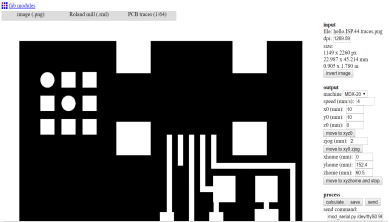
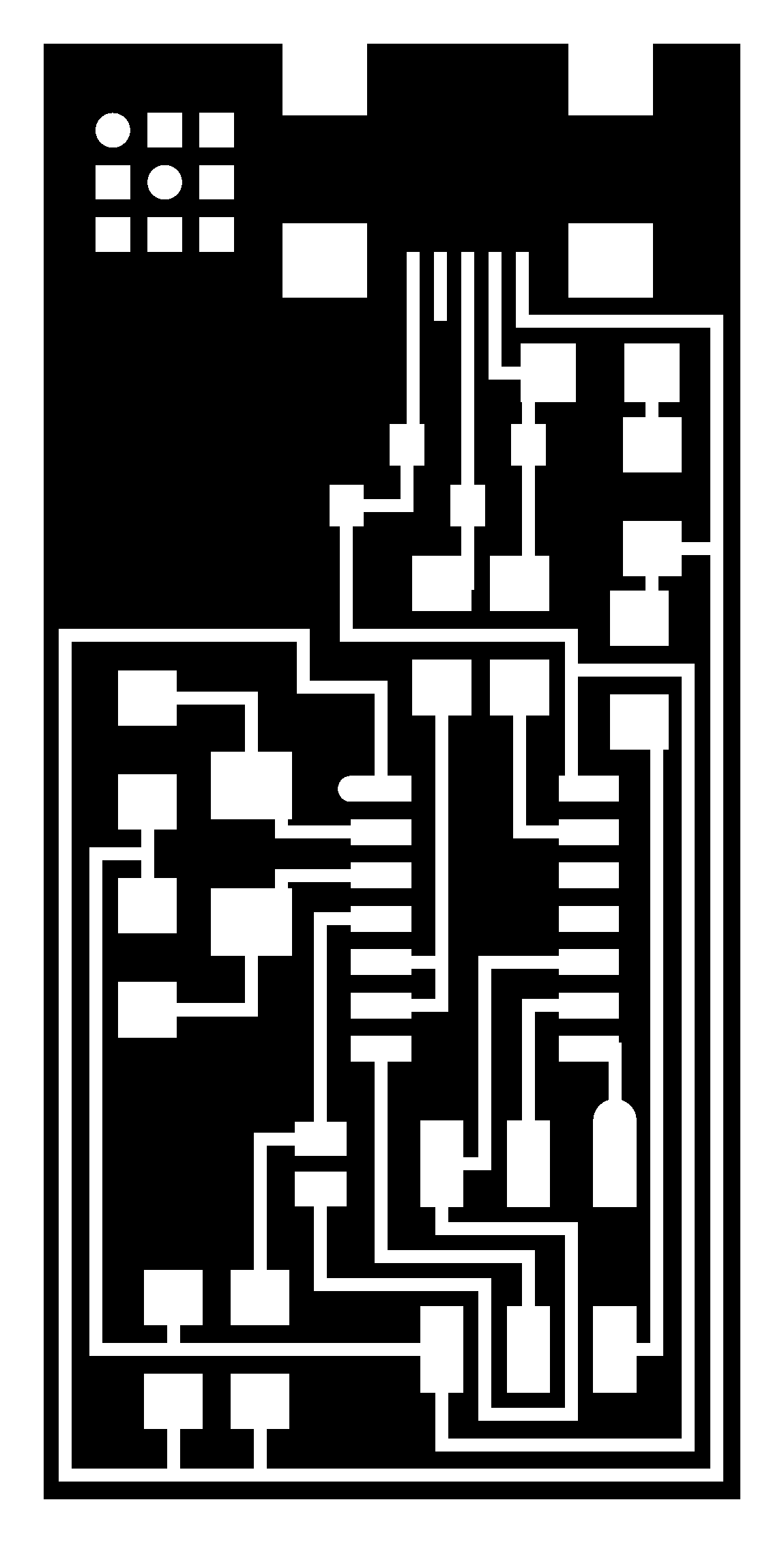
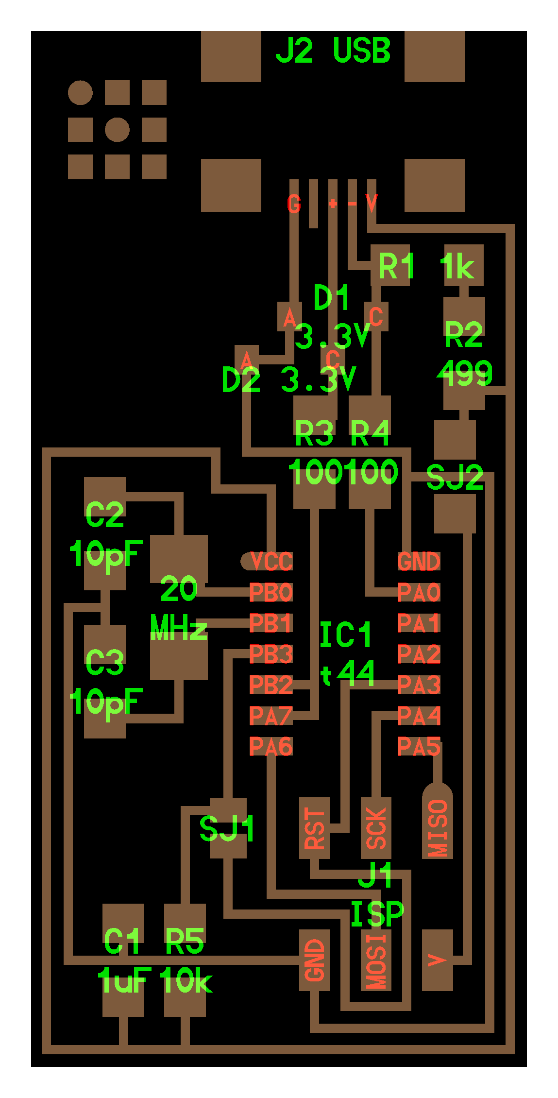
Preparing the CAD
I opened fabmodules.com, since our Roland milling machine for some reason hasn't been set up for use with Mods. I then set the image to be the traces image, set the "Output format" to be rml, Process to "PCB Traces 1/64" and in the dropdown on the left selected MDX-20, which is our machine. I then set x and y to start at coordinates to the closest left corner.
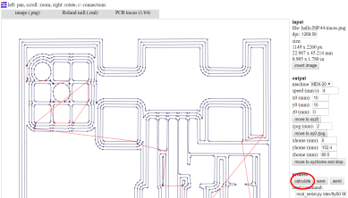
Calculating path
When you press "calculate", it will calculate the path based on the cut depth, tool size, offset and so on that you selected for your path. It then draws it for you, and when you hit "send" the Roland MDX-20 will start following the CAD instructions you just generated.
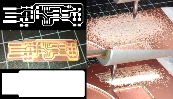
Milling the board
There are several things to keep in mind when milling a board.
- The order: Trace first, then cut, otherwise there is a risk of the board coming loose and being misaligned.
- The milling bit: 1/64 inch for tracing, 1/32 inch for cutting
- The depth: 0.2 for tracing, 0.6 for cutting
- The position on x/y, positioning it to minimize waste, but preserve integrity
- On our machine, we needed to change the way the computer communicates from "USB" to "S" since it's connected via a different connector than USB.
We are very fortunate to have detailed instructions in video and text format that guide us step by step in the use of our PCB milling machine.
Icelandic instructions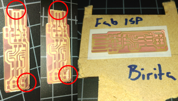
Cleaning and improving
In retrospect, I am fairly sure that the 1/64 inch milling bit broke toward the end of the tracing run. Part of the top right corner did not get milled away properly. Additionally, I cut the board with only 3 offsets, which left some copper at the far left edge which needed to be removed. I used a sharp knife to clean away these faults, which worked well.
I deburred the board carefully, then cleaned it with dishwashing soap. After patting it dry with a paper towel, I stuck it to a piece of leftover wood with double sided tape. This made it easier to work with for the soldering phase.
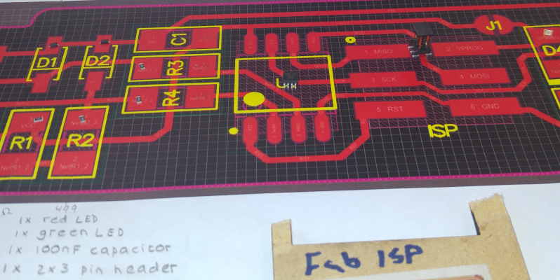
Finding components and preparing
In preparation for the soldering, we printed the layout and component overview. I then gathered the components required and placed them on the diagram to ensure that I wasn't missing anything. One issue we faced was that we couldn't find any 100nF capacitors. Knowing that our manager would not have made such an oversight, I decided to research what the numbers and units mean on a capacitor.
My research quickly yielded results. Three types of units are used for capacitors. Microfarads (µF) Nanofarads (nF) and Picofarads (pF) As it turns out, 1000 Nanofarads equal 1 Microfarad, so 100nF=0.1µF.
Handy Capacitor conversion chart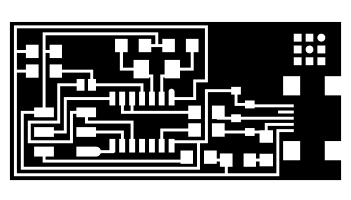
UsbTiny not found, HelloISP
After repeated trials, measurements and attempts at using the FabTiny, we gave up. Programming it went fine, but it could not be found by the computer when it came to using it to program a hello board.
For my next attempt, I will use a tried and true Fab-isp trace, hoping that a familiar appearance will make it easier to troubleshoot.
Hello ISP 44 Traces Interior Guide
A 2nd attempt
The second attempt went faster than the first, which is to be expected. I was also much happier with the soldering on this board than the previous. I had one hang up in the production process, which was to figure out what "20 mhz" stood for. When I discovered that it was a regulator I got even more confused, since the regulators I could find all had three feet. After some more research I discovered that regulators with larger numbers tend to be crystals, which only have two feet.
I hope that with Frosti's help I can program this in-circuit programmer to behave itself properly. As is, it displays as an unknown usb device on my windows computer, and does not display on the Ubuntu computer when the lsusb command is used.
programming guidelines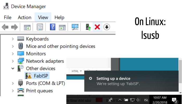
It works!
As it turns out, the problem was that I was using the wrong firmware. We donwloaded the correct zip, unzipped it and used it to program the ISP. Now, when plugging it into a computer, the windows computer correctly identifies it as "FabISP". This makes me do a little happy dance every time it happens. We used Zadig to set up the correct driver on the computer.
On the Linux computer we used to program it, I typed "lsusb" which lists all usb devices currently connected. It identified the Fabisp as "unidentified tinyusb", which is the same as it displayed for our control.
Bas Withagen helped me with this part while we were all visiting the Sauðarkrókur fablab. I did not think to take pictures of the process, but it involved replacing several resistors that had the wrong value before doing some programming magic on the local windows machine. The man is a wizard. I am not. Yet.
ZadigFab ISP programming step 1: Set up required software
To program the FabISP, you first need to install the necessary software for your operating system and download the firmware. I did not have to do this, as our lab has some ancient Linux laptops which are only brought out for this particular purpose every few years when there is a fab academy group that needs to program their ISPs. We use the terminal on those Ubuntu machines to do the next few steps.
Fab ISP programming step 2: Editing Makefile
Since we were using our old Linux computers, I typed nano Makefile into the terminal, and a window opened containing the Makefile. I found these lines in the code:
#AVRDUDE = avrdude -c usbtiny -p $(DEVICE) # edit this line for your programmer
AVRDUDE = avrdude -c avrisp2 -P usb -p $(DEVICE) # edit this line for your programmer
I deleted the # in front of the line for the usbtiny and added a # in front of the avrisp line. The hashtag comments out the selected line of code, which means that the program sees it as a "comment" and not executable code. I then saved the makefile again.
Fab ISP programming step 3: Setting fuses and programming
In the terminal, I called up the firmware like this: "cd Desktop/2018/firmware" cd means "call directory" and is followed by the path to the location where we saved our firmware.
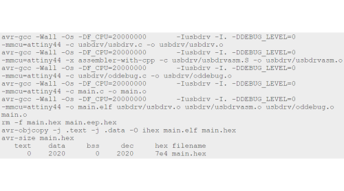
I typed "sudo make clean" and typed our password to execute the command. When we just typed "make clean" the security prevented us from executing the command because it was expecting a "sudo" in front. This command gave me this response:
rm -f main.hex main.lst main.obj main.cof main.list main.map main.eep.hex main.elf *.o usbdrv/*.o main.s usbdrv/oddebug.s usbdrv/usbdrv.s
This means that it worked. I then typed "sudo make hex" which gave me the response on the right.
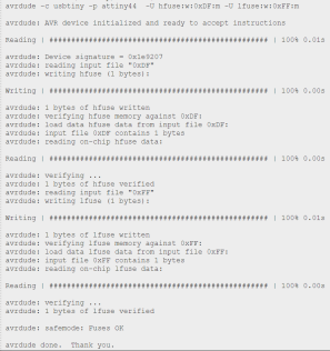
Fab ISP programming step 3 continued: Setting fuses and programming
In the terminal, I wrote "sudo make fuse" which created the reaction you see on the left. First, it reads the signature of the programee, making sure that it is the correct sort of microcontroller for the operation. Then follows a process where it verifies that each step has been executed properly before it goes ahead with the next step. It writes the fuses to make the internal clock behave the way we want it to.
The most important part is that it ends with "avrdude: safemode: fuses OK" and doesn't return any error messages. Then you can write "sudo make program", which brings on another, even longer process of reading and writing, confirming that each step is properly executed until you again receive "avrdude: safemode: Fuses OK avrdude done. Thank you" This means that you are done! My fabISP was ready, so I desodlered the solder jumper, turning it from being a programee into a programmer. I kept the solder jumper that allows the programmer to power secondary boards, but I don't recommend this. Much later, I would up removing it because it was causing regulators to pop on other boards, and made the programming process much more frustrating. It is better to get used to powering your boards with a secondary source from the beginning.
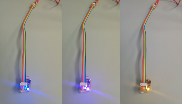
Hello RGB
I made a simple RGB hello board before the course, and this was a perfect chance to try programming something with my FabISP. I used the lab's Linux computer to program the RGB hello board to cycle through various colors. I edited the code slightly to make it start with green rather than red.
An added feature of this FabISP is that it currently has a 0 ohm resistor bridging SJ2, which enables the FabISP to power secondary devices that are connected to it. As can be seen in these images, the Hello board is not connected to any other power source.
I grabbed the files from the archive entry for output devices, but decided to include them here as well, for completion's sake
Traces Interior Makefile C-file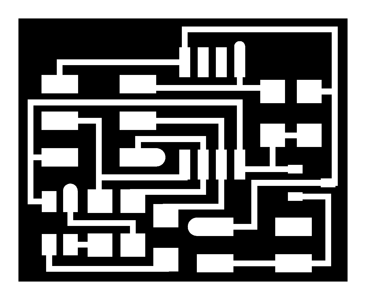