This week, the individual assignment is two-fold. We need to scan a 3D object and we need to print a 3D object. I chose to scan my son's favorite stuffed toy, thinking that it would be fun for him to have a tiny version of it he can use as a game piece in board games. The 3D print is a bit more ambitious, and is the prototype of the power generating mechanism that will form the core of my final project.
3D Scanning 3D printing Group AssignmentThe most easily accessible 3d scanning method is photogrammetry, which uses a series of 2D images to create a more or less seamless whole 3D image.You have to be sure that the background is static, and should place other objects around your target, to help the program correctly align the images. It is more difficult to scan furry objects, and objects which reflect lights will not scan properly, as the photogrammetry software cannot properly process the reflections.
Photogrammetry uses math to calculate the relative position of features in photographs. In order to splice photos together, it refers to where the camera is positioned, and cross references specific easily identifiable features to correctly map out where everything is in relation to everything else.
Always up for a challenge, my target is furry, rounded and uneven, and tricky to pose. In addition, the eyes are reflective. I used various items around the lab as reference points for my photographs.
More on PhotogrammetryRecap is a part of the Autodesk suite, and offers an easy way to 3D scan objects by using your phone. With Recap, I used over 50 2D photographs which the program used to create the 3D model.
The interface is intuitive, the wait time acceptable and on my first attempt, the program created a usable if imperfect result. One side of my target came out skewed, as if the program had trouble aligning the back of my target properly. This may be due to the uniform nature of the back of my target. Still after using the sculpting tool to nudge the misaligned side back into place and the gap filling tool to fill in the holes, the result is usable for the purpose of printing.
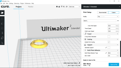
OBJ fileRecap file Get RecapI decided to print the model I scanned using Recap, as it is my favorite of the scans I captured. When I loaded the stl file in Cura, I discovered that the model was seriously tiny. I upped the size by 600% and wound up with a 2,5cm tall model. I printed it using a brim, 25% fan strength for the first two layers and supports touching the buildplate with 1 mm distance to the model. It worked out beautifully, and I can't wait to paint the model.
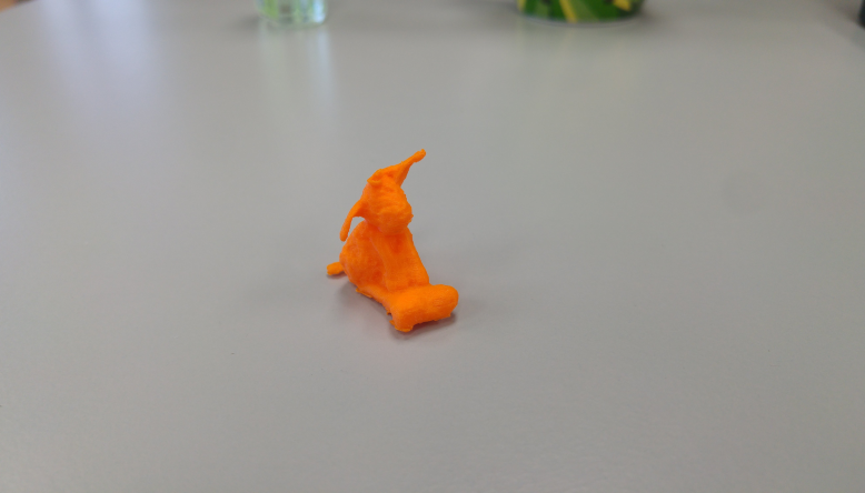
As a sidenote; the above settings were derived from the experience I gained from our group project, where we tested the settings of our 3D printer.
STL file for printingWe have a Next Engine 3D scanner in our lab, which uses a combination of images and multi-laser parallel scanning technology to create extremely high-detail scans. The hardware is excellent, and easy to work with. Unfortunately, the accompanying software is extremely slow and heavy, and the gap-filling does not work very well at all.
I did not get a usable scan out of this, as it took up to an hour between the clicking of a button to the execution of the command in the program. Most likely such accurate and powerful software requires a very powerful computer to function properly, and our computer isn't up to the task.
Product websiteI downloaded the free version of this app to my phone, as it appears to be the highest rated 3Dscanning app for Android, despite only earning 3 stars. The app using photogrammetry, but what is different from the other programs is that this one is in your phone, guiding you as you take your photographs. It guides you by telling you how to start your photo sequence, then overlays dots on the model, which turn green when you are in a good position for the next photo.
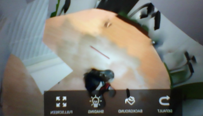
Guided by the app, I took about 70 photos of the same model as before, then hit a button in the app which tells it to calculate the 3D model. This took about 15 minutes, including the setup of my workspace, arranging other items, posing the model etc. The phone took a few minutes to calculate the model, which came out completely unusable. The free version of the app allows you to take screenshots, but you can't export said screenshots, nor find them in any image folder on your phone. Hence the very poor picture I took of my screen, which was the best export I could get of this model without paying for an upgrade. In short, this app may be very good, but for a beginner who wants to try it out, it is not worth the time and effort, compared to the much better results gained from Recap.
App pageIn the interest of comparing software, I decided to give 3DF Zephyr a try as well. I tried the free version, which allows for up to 50 photos. I used the same photos as I used for Recap, in order to facilitate a fair comparison. One of the things I like about this program is that it informs you of where it is in the process. The downside is that the computing happens on your own computer, while Recap does the computing in the cloud. Since your computer is weighed down processing the photos, it limits the amount of work one can do in the meantime.
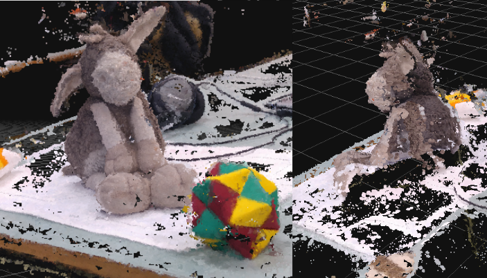
While the front of the scan worked fine, again there were issues with the back. Possibly because I did not have a good enough arrangement of identifiable objects around that side, possibly because the camera is further away from the target object than it is on the other sides, due to the shape of the table and possibly because of the uniform nature of the back of the toy.
3DF Zephyr pageIn my final project I will need the ability to have magnets spinning very fast along with a vertical wind mill. This requires some sort of bearings that allow the magnets and mill to spin freely while otherwise keeping them firmly secured in their place.
At first, I researched ball bearings, specifically the type that can be printed in place, thinking that they would be ideal for this purpose. However, during my research I discovered incredibly good instructions on how to design parametric slew bearings.
Created by Christoph Laimer, the instructions take you step by step through creating parameters, drawing the sketch and extruding the design. This process helped me gain a much deeper understanding of how to use parameters in 3D design.
InstructionsI expanded the sketch to include an area for the magnets, a coil holder and a second bearing at the top, tying it all together. It should be noted that this design is flawed and does not create any electricity. In order for it to work, the coil must be arranged perpendicular to the axis along which the magnets spin, not parallel. This will be rectified in future designs.
I measured my magnets and added parameters to the design to incorporate them perfectly.
Fusion 360 fileAdditive creation methods are methods by which material is "added" to create the design the creator envision. Subtractive creations methods in stead "subtract" material from a chunk to achieve similar results. One of the key benefits of additive manufacturing is that the tool you use to print with, in this case the "nozzle" can move freely until the layer has been added. There is nothing in the way, which is why it can create complex shapes with holes and odd shapes on all sides.
The primary reasons why this design should be made additively and not subtractively are the bearings and the magnet holder. The bearings include a v shaped indentation along the interior of the whole race. This would be prohibitively difficult to create in subtractive processes.
The magnet holding element is circular, with races along the top and bottom and holders that enter it from six different angles. This would be a nightmare to create subtractively, but is done with ease in an additive process.
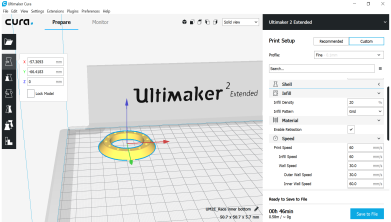
I used fairly standard print settings for all these prints. I picked the pre-set "fine" profile, changed from the raft to the brim (since the raft is unnecessarily cumbersome for flat items like these), changed the initial layer height to be 3mm for added adhesion and chose the triangular infill type, as it is slightly faster without loss of integrity compared to the hexagonal. I did not find that these prints required any support, although some required light sanding afterward. I kept infill density at 20% although I am certain now that 10% would be plenty.
I like to place my prints as far back as possible, because the heat is more constant there, which minimizes warping. I also like to put my designs in the corners rather than the middle, so that we don't wear the middle of the rails down faster than the rest of them.
Our printer is an Ultimaker 2 Extended, and when I originally printed this, it was not properly calibrated and we were not good at setting it up, so we had to use a brim, gluestick, door and thicker base layer in order to have acceptable adhesion. Since then, Carl came to finish Fab Academy with us, and he is some sort of 3D printing wizard, so now we don't need anything more than good printer settings to get perfect adhesion. Since he came and calibrated our printer, print times went down by hours, and the prints come out better than ever. (Hire him)
He noticed that our printer needs to be set to higher temperatures than the ones in Dubai, and he deduced that this was most likely due to our much lower ambient temperature. Since then, we printed at higher temperatures, and everything has been working more smoothly
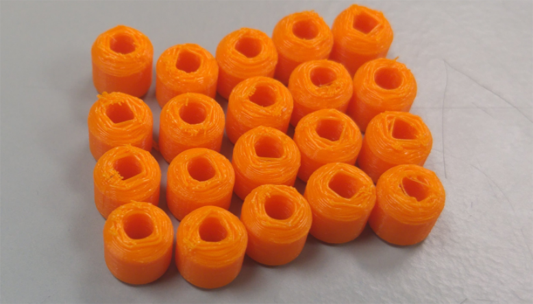
CarlOne of the limitations of 3D printing is that the prints generally require some work before they are usable. For example, these 20 rolls all needed to be individually sanded and worked before they were smooth enough to use in the mechanism. For the bearings, it is critical that they are wider than they are tall, as only the rotating sides should touch the races, the ends spinning without friction. This is one of the things which would benefit from being molded and cast, as I needed 40 of these, and they took 6 hours to print, followed by 2 hours of sanding and cleaning.
To assemble the slew bearing you place the outer race on the table, with the inner race inside it. Then you arrange the bearings inside tilted alternately towards the inner and the outer race.
Once all the bearings have been arranged, you place the second inner race, in this case, the magnet casing on top, securing the rings together.
And the moment of satisfaction comes in. The design works as far as the spinning is concerned. It began rough and loud, but after some grinding it back and forth, and adding lubrication, it spins much better.
On the whole, this was a very satisfying prototype creation. The parameters are fine, the spinning works, and the print was of a high enough quality that it required only minor sanding and post processing. There was some minor warping of non-critical areas, such as the outside of the races, but this has no impact on the functionability of the model. In cases where the warping is unacceptable, I will use my new knowledge of fan settings to combat it.
.While 3D scanning is very cool, it requires some skill to do well. Recap is the easiest tool to get into, and is freely available to educators and students, so I would recommend that those who are interested start there.
Fab Academy Next page