On this lesson we will cover how to make 3D objects by adding material such as molten plastic. We will also learn how to scan 3D objects. A 3D object is one that is not flat like a sheet, but voluminous like a ball.
3D printing is done by depositing melted material in layers to form a 3D surface via several successive layed 2D Fused Deposit Modeling material depositions. It is called 2.5D. Proper 3D printing would be if the material was displaced in all 3 axes at the same moment.
The LASER cutter we saw in the computer-controlled cutting lesson also produces 2D pieces and makes 3D objects by this 2.5D process.
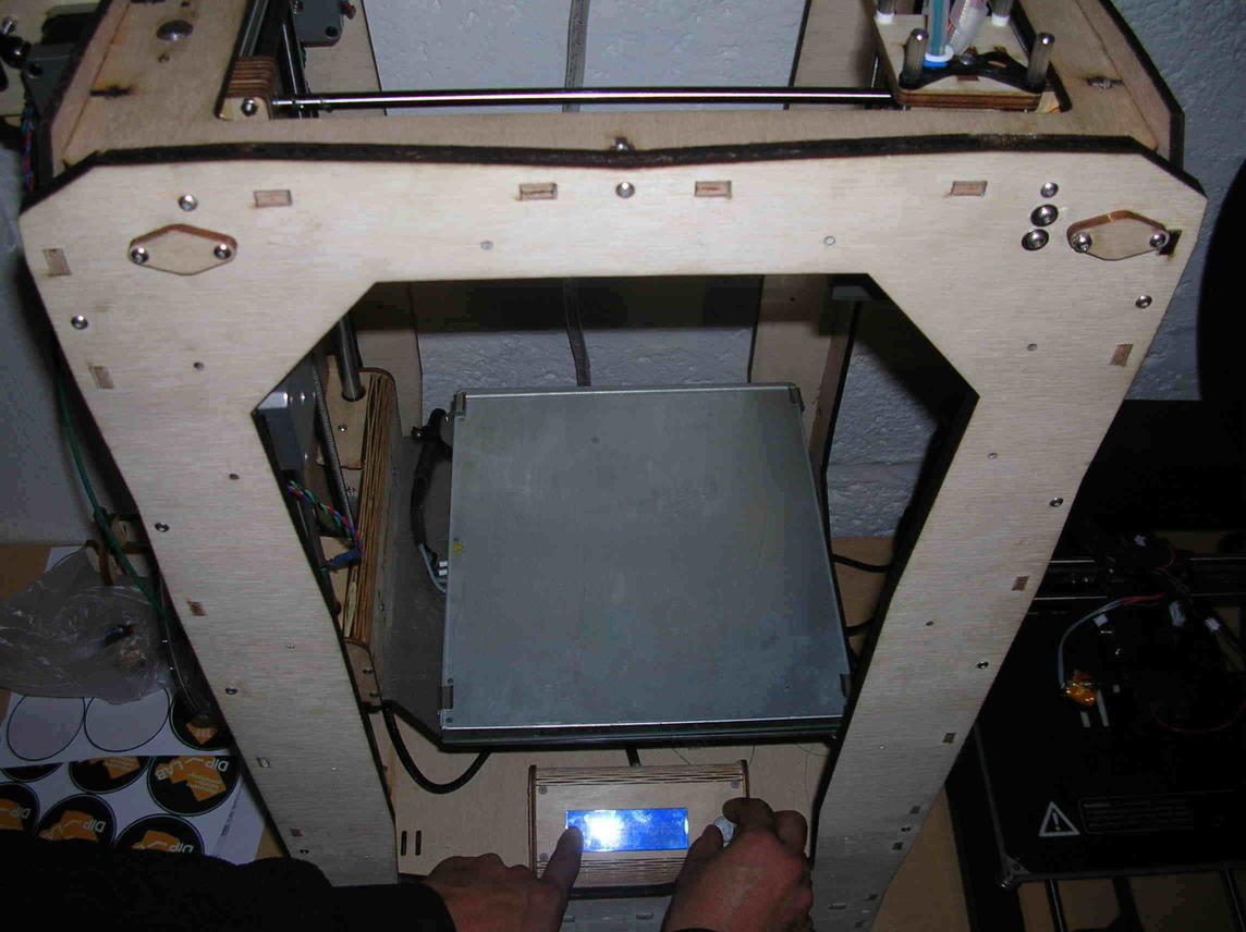
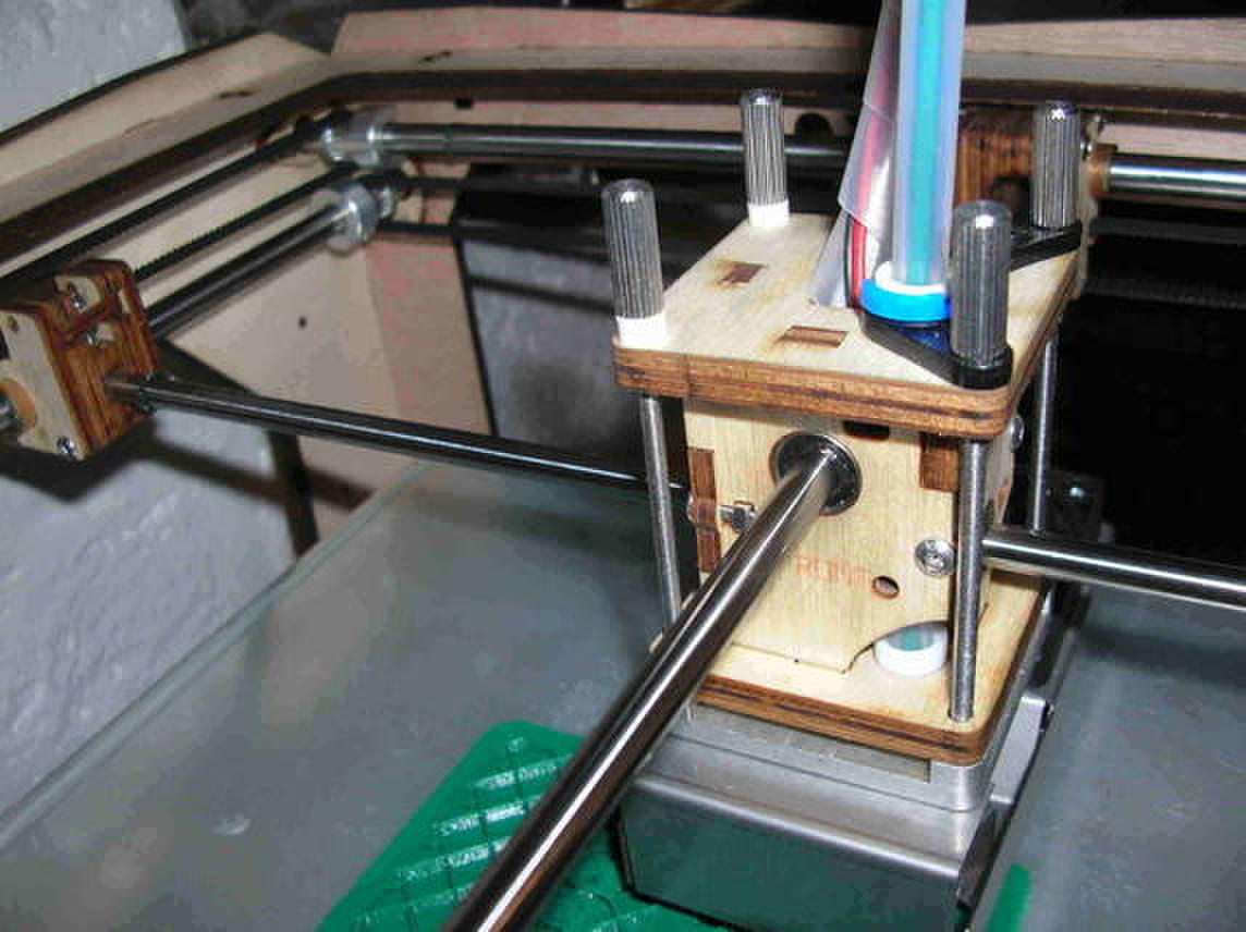
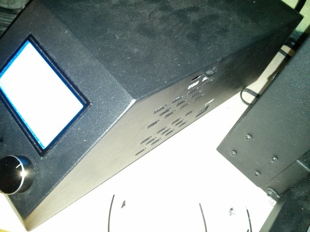
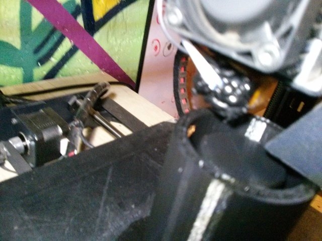
We are using an Ultimaker. It was made in the Lab.
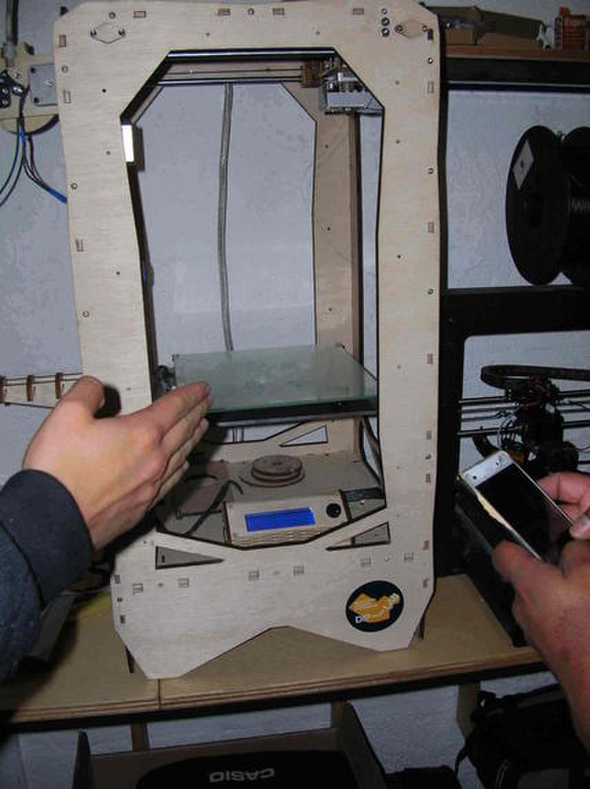
The base moves vertically and the deposit head moves on the horizontal plane.
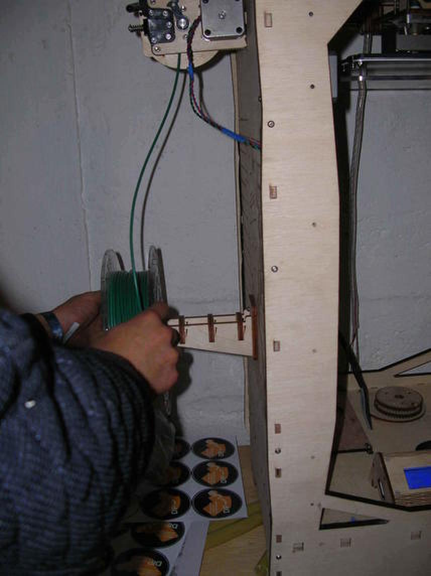
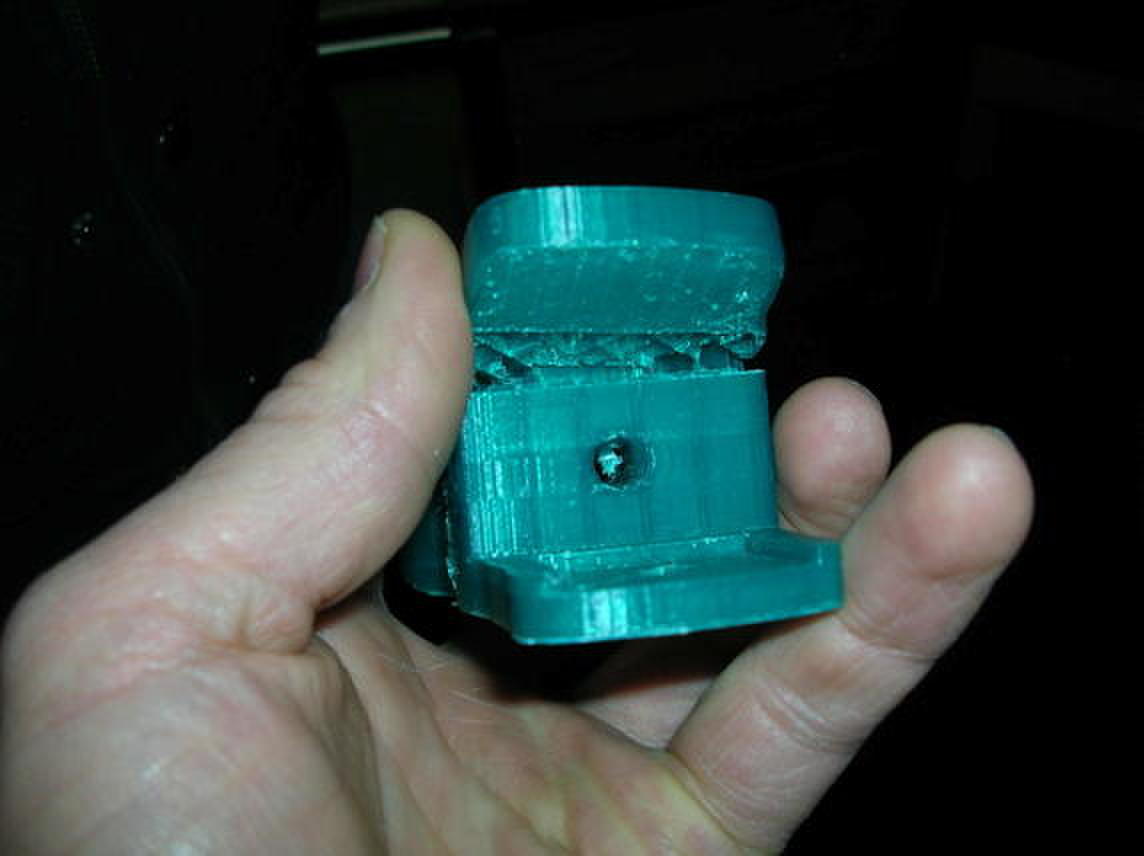
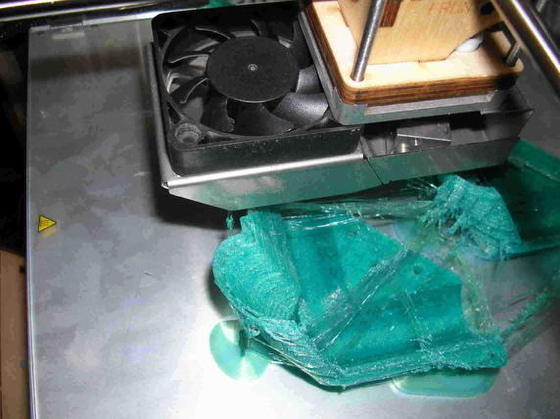
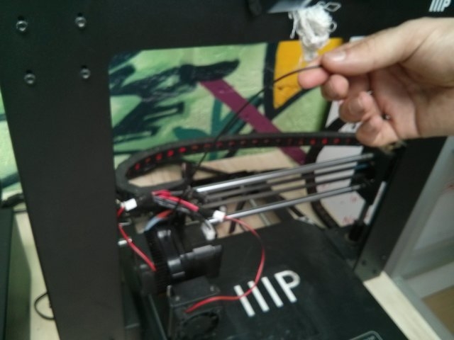
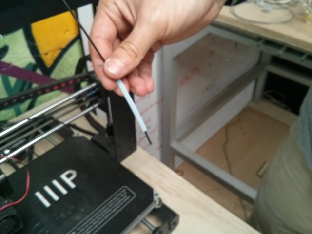
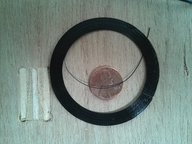
This is the material that the Ultimaker deposits.
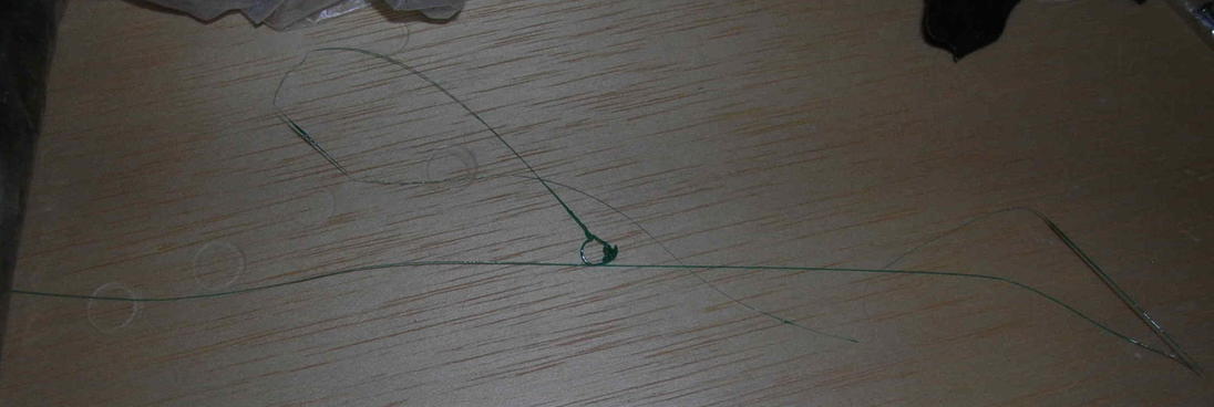
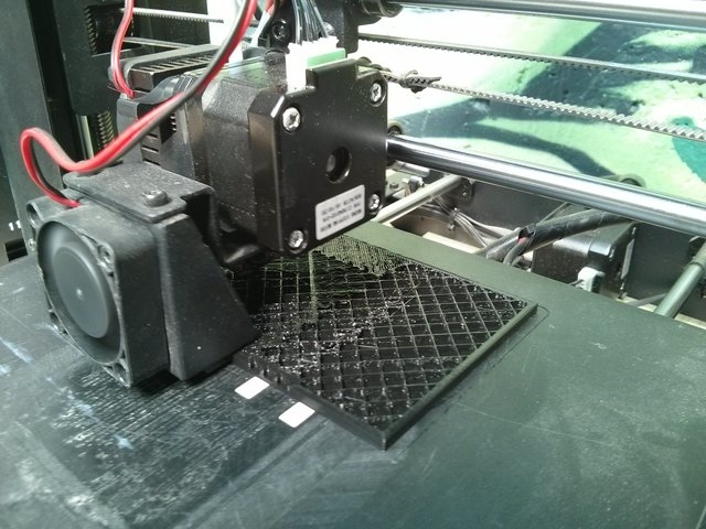
This is a portion that went offline.
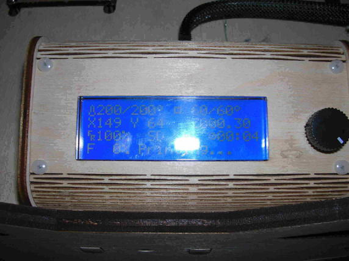
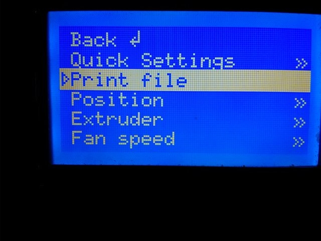
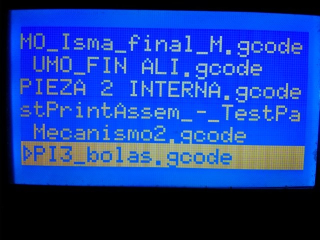
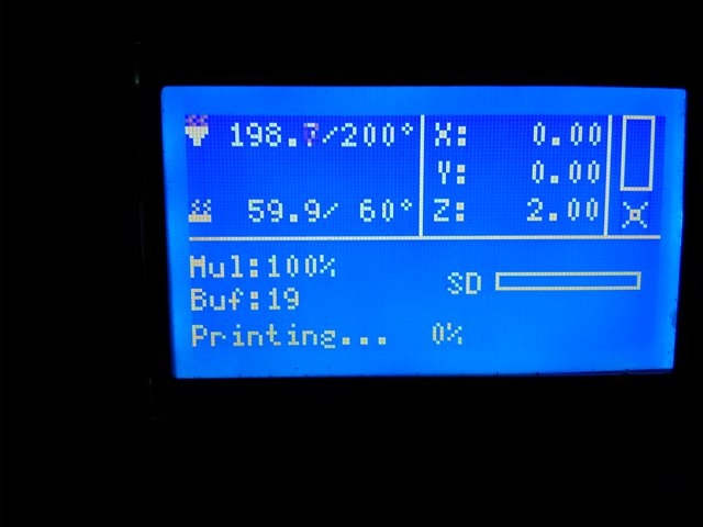
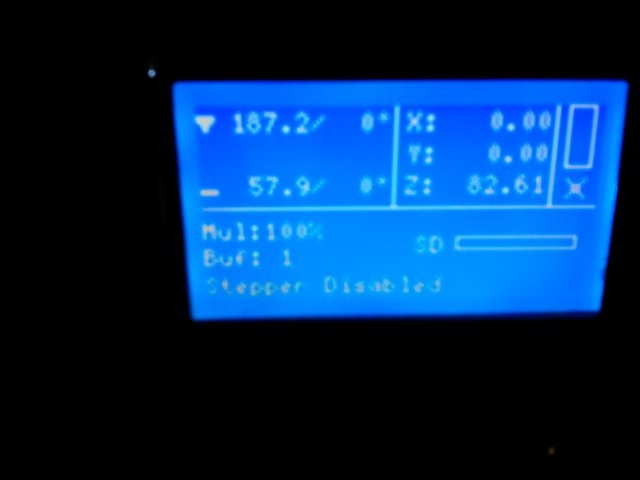
The control panel
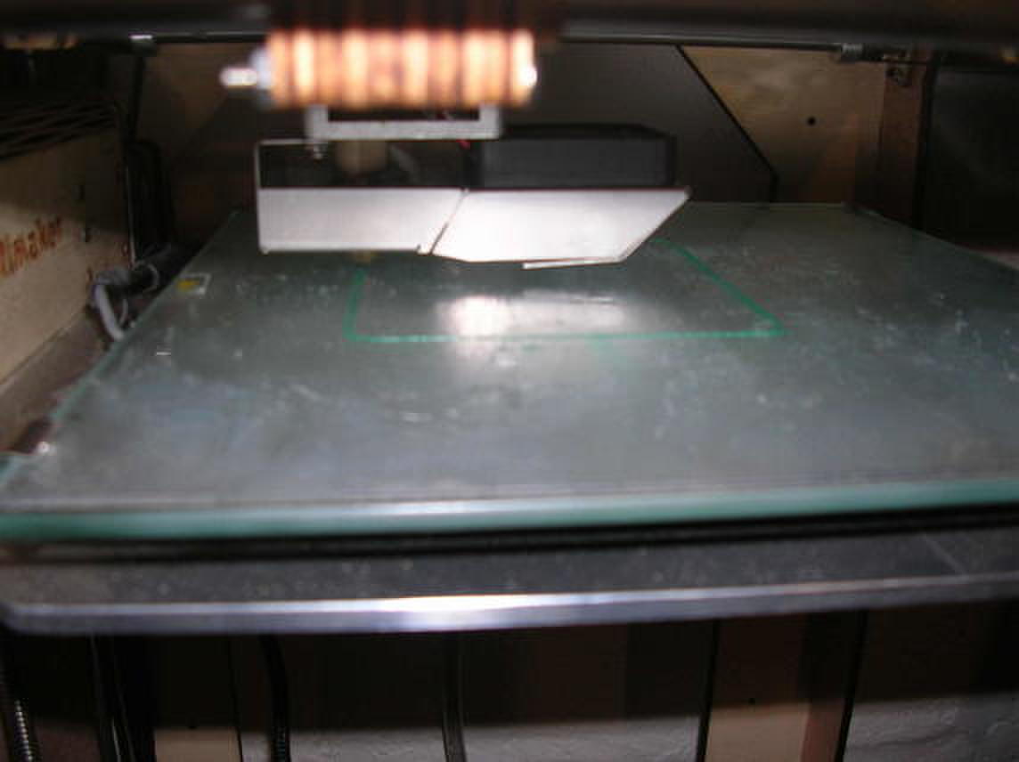
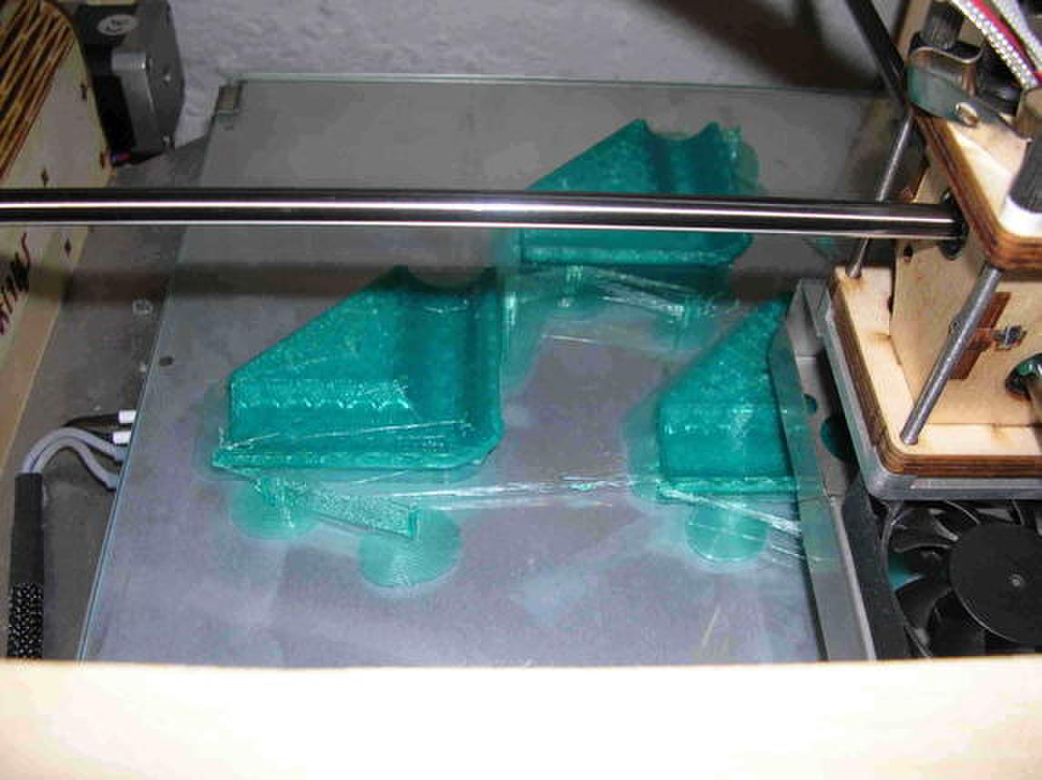
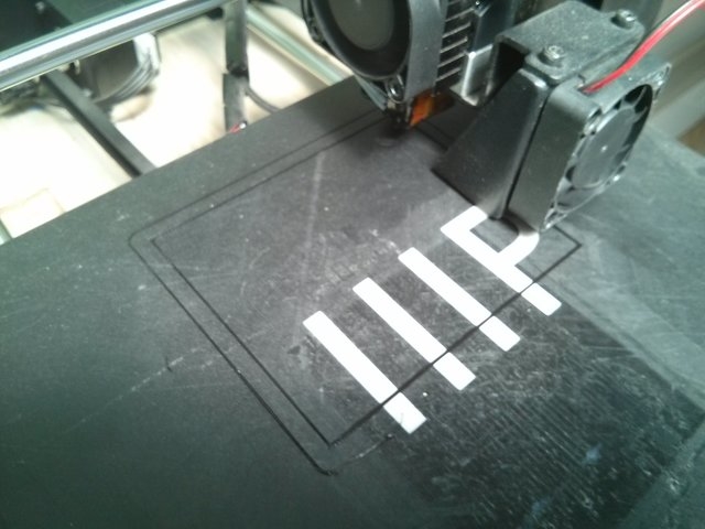
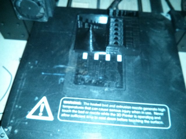
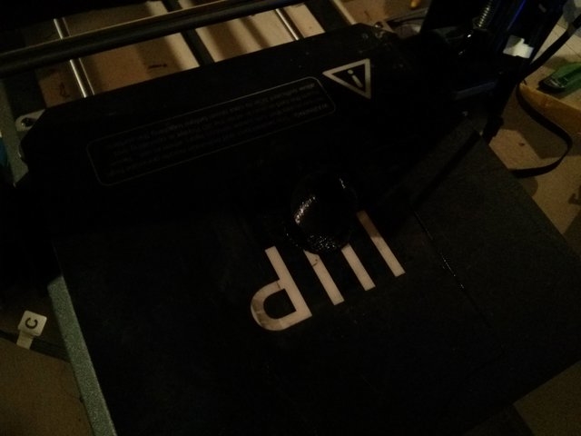
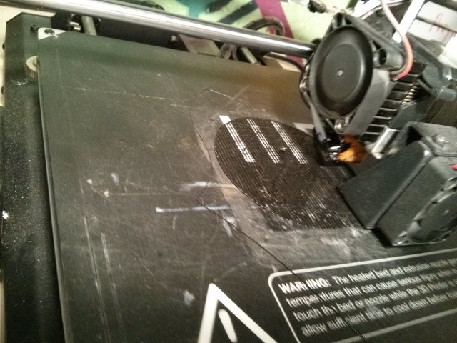
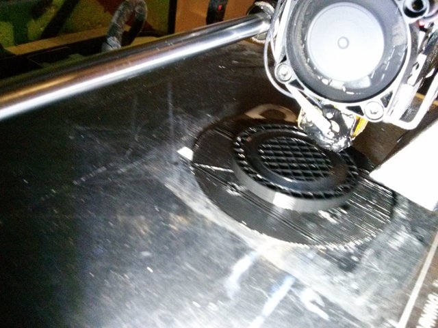
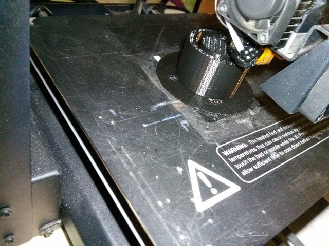
The machine in action printing a piece.
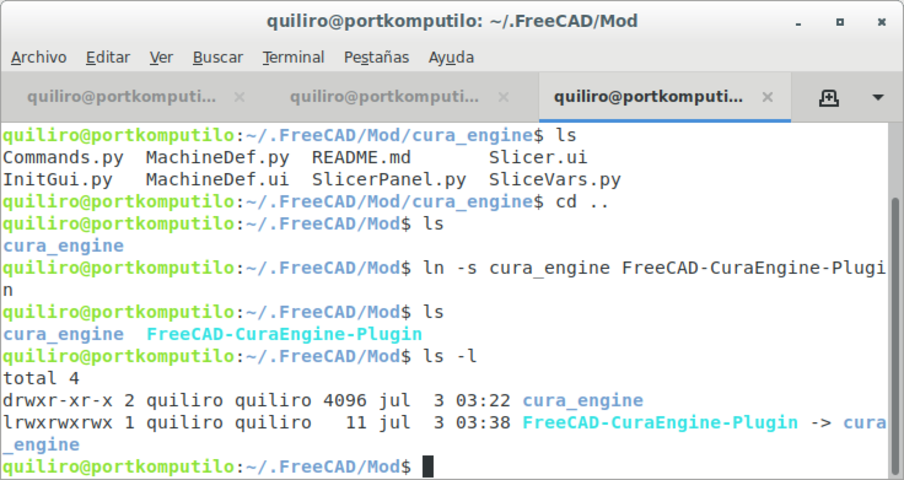
I had not been able to find a libre software which would allow me to transform a group of images in a folder into Gcode.
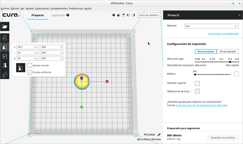
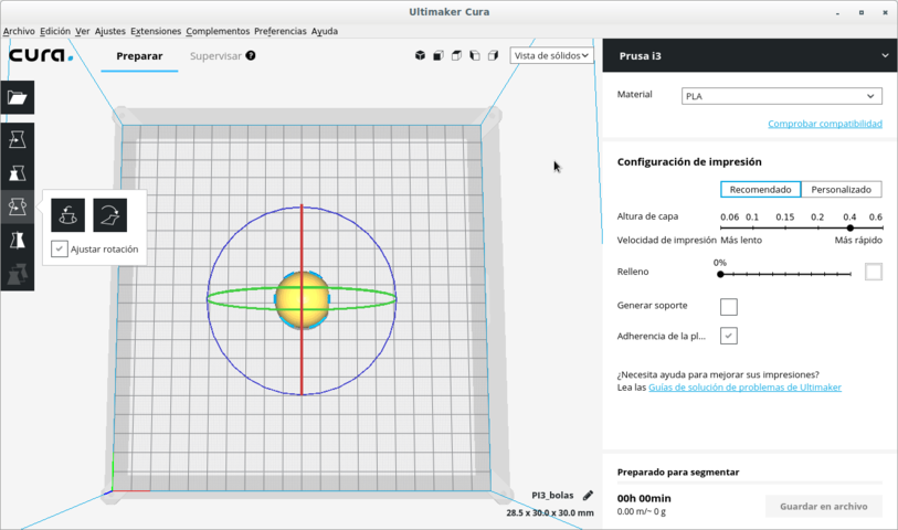
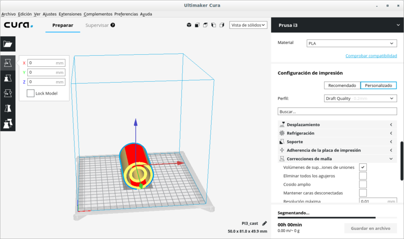
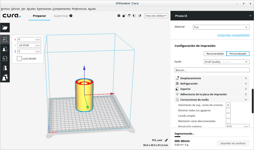
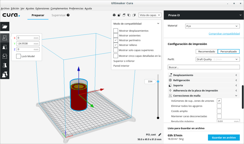
Open Stl file - select object - Extensions - Auto orientation - Calculate extended optimal printing orientation
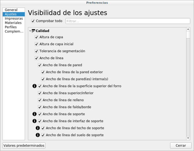
Adjustments - Configure adjustment visibility - Check all - Close
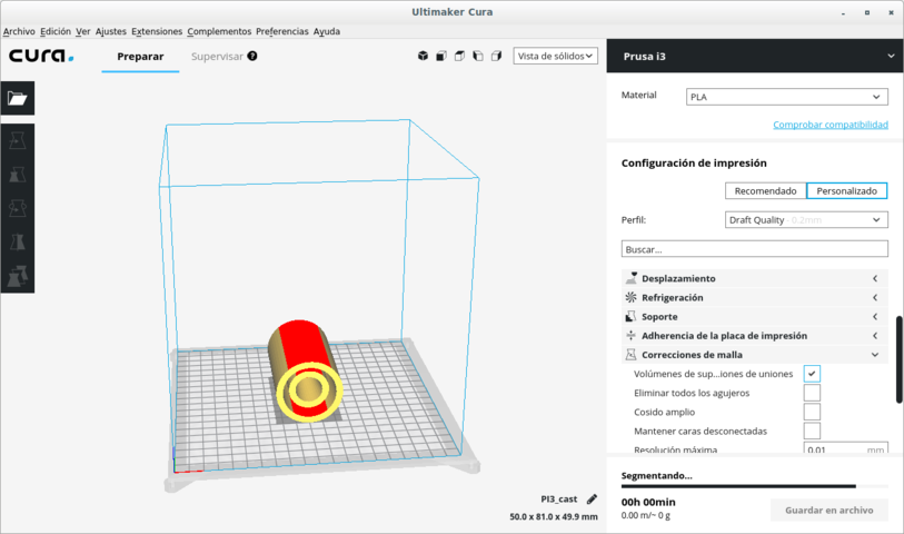
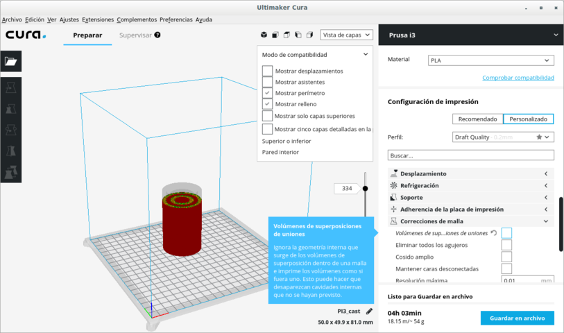
Mesh correction - Superposed union volumes (unchecked)


Several methods can be used to scan in 3D.
We are using Kinect. It is a hardware device that has a USB communication port. It holds a video camera and an accelerometer. So it can effectively scan while it moves.
Since the software that comes with it is non-libre, I have investigated OpenKinect. It produces two sets of files in a directory. One type is for the photos and the other type is the accelerometer data.
The Kinect produces images with holes in it where it did not get a good view. We must use software to fill holes. The surface must be water tight because it is only possible to print in 3D a surface which is sealed.
We must export a model in OBJ or in STL formats. Then we must print it in the 3D printer.
Installation
sudo apt install freenect
Installing libfreenect support library, for using Kinect with libre software.
guix package -i freeglut libxi libxmu
Running it
freenect name_of_new_directory
So it creates this directory and fills it with the images and accelerometer data that it detects until Ctrl-c is pressed. It is a great amount of data. So I will not upload it to the repository.
A live showcase of the real-time data from the Kinect is shown on the monitor with the command:
freenect-glpclview
I had tested several libre softwares designed for photogrammetry (exact position measurement of physical objects in 3D by way of photographs in 2D) with different problems:
I did not consider very important the difficulty or ease to learn the software. Mi main concern was freedom. Sooner or later it would be something that would afect my life and the lives of others. So I started with a step in the right direction.
MIC-MAC is the only libre software which I could install successfully and can be fully used in freedom for photogrammetry. This is so because all others must use nonfree firmware (onchip software) for the graphics card in order to use image recognition acurately and with all its power.
MIC-MAC is a professional grade photogrammetry tool for data from videos, aerial photography, architectural photography or small object photography. It is designed to be able to measure with incredible precision. I have chosen it because it was the only libre software which would work with the CPU (Central Processing Unit) instead of the GPU (Graphical Processing Unit). This is important because most graphical hardware runs well only with non-libre software. That is a risk to the user's freedom; hence the importance of MIC-MAC. (Its quality is extra.)
sudo apt-get install make imagemagick libimage-exiftool-perl exiv2 proj-bin qt5-default qttools5-dev-tools libx11-dev
      git clone https://github.com/micmacIGN/micmac.git

      cd micmac

      mkdir build

      cd build

      cmake -DWITH_QT5=1 -DWITH_CPP11=1 ..

      sudo make install
At the end of .bashrc add:
	export PATH="/home/quiliro/MICMAC/micmac/bin${PATH:+:}$PATH"

	export LD_LIBRARY_PATH=$LD_LIBRARY_PATH:/home/micmac/lib/
Below I detail the journey I took for learning how to make very newbie user initial photogrammetry of a small object in order to obtain a mesh for using on 3D design to feed 3D substractive or additive printing.
The best route to follow for learning MICMAC is to experiment with the MICMAC tutorials exclusively their own photos.
But I wanted to find out how the photos I could take myself would work with this software. So I had many problems I wouldn't have had if I would've experimented outside the box after doing it in a controlled environment (with the tutorials). I did not know the basis of photogrammetry and I would try to drive the Ferrari Testarosa of photogrammetry software by just knowing the place I was headed. I opened a thread on the forum with my http://forum-micmac.forumprod.com/error-with-basic-reconstruction-t1657.html.
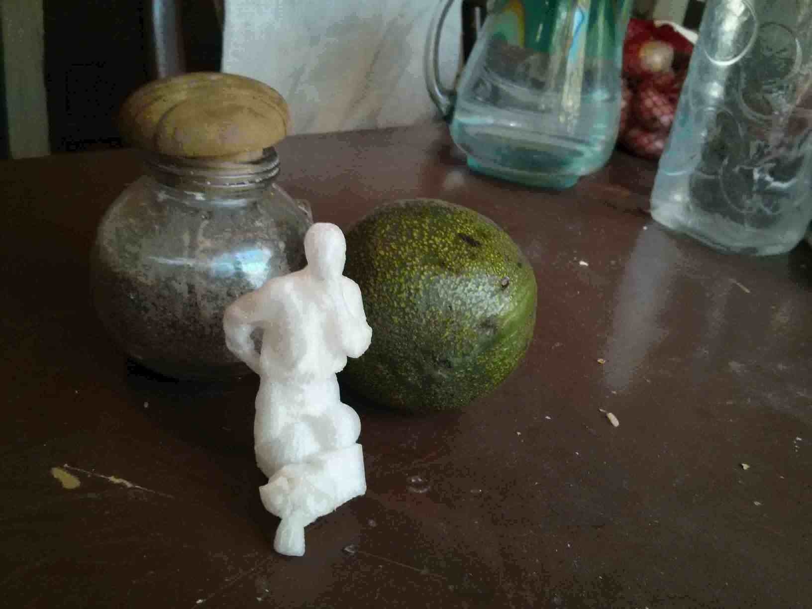
I tryed taking photos of an apple by rotating the apple and keeping the camera still.
I asked many questions and made many tests about photogrammetry detailed on the forum thread. With that information on mind I made a wire-hanger apple pedestal with accompanying guard dog!
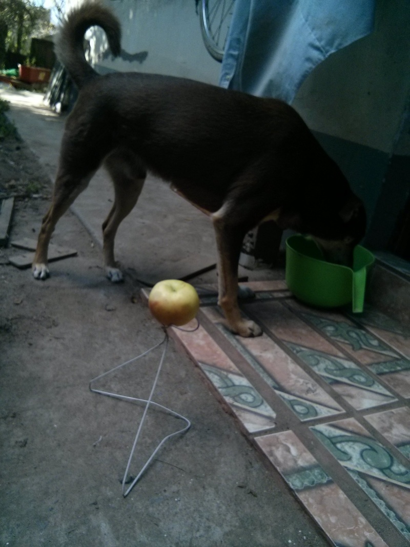
They told me at the forum to keep the object still and take unblurred pictures from all around the object. (I made all the errors that can ever be made. Hence all the info on this document!)
First I found the tie points.
      mm3d Tapioca All *.jpg -1


      "IMG_20181210_160443.jpg": 1 matches.

      -----------------------------------------------------------------

      |   KIND OF ERR : User's error

      |   Sorry, the following FATAL ERROR happened

      |

      |    LArgMain , Don't understand :[IMG_20181210_160505.jpg]

      |

      -----------------------------------------------------------------
But I had a minor regular expression syntax error. I corrected it and had a flawless execution then.
mm3d Tapioca All ".*jpg" -1
So I continued with the orientation phase.
      mm3d Tapas RadialStd ".*jpg" Out=Cal1


      BEGIN Pre-compile

      WARN  !! , for camera Nexus 4 cannot determine focale equiv-35mm

      add it in include/XML_User/DicoCamera.xml

      "NKS-Set-OfPatternAndFoc@[[.*jpg]]@0.000000@100000.000000": 10 matches.

      ------------------------------------------------------------

      |   Sorry, the following FATAL ERROR happened

      |

      |    cMetaDataPhoto::Foc35 UnInit

      |

      ------------------------------------------------------------

      -------------------------------------------------------------

      |       (Elise's)  LOCATION :

      |

      | Error was detected

      |          at line : 992

      |          of file : /home/quiliro/MICMAC/micmac/src/util/dates.cpp

      -------------------------------------------------------------
I had this error for weeks. It was the camera which did not report on the photo metadata what was the length of the lens. This was basic data that could serve for calculating the focal 35mm distance (F35). F35 would help find the camera orientation of each photo. I did not know this parameter so I included only the ones I discovered from the metadata or by investigating the camera specifications on internet. I fed that data to the photos.
mm3d SetExif ".*jpg" F=4.6 F35=33
But I would still get the same error I had about the focal distance simulation at 35mm (F35). So I would remove the temporary directory for calculations and try again with something else. Always I would change SetExif parameters and then get the same error from the following steps.
      rm -rf Tmp-MM-Dir/

      mm3d Tapioca All ".*jpg" -1

      mm3d Tapas RadialStd ".*jpg" Out=Cal1
After several failed tests with other sets of pictures under different conditions but with the same camera, I decided to change camera.
It made all the difference in the World! This camera had a lot of metadata that the program could work on. Especially it had the F and the F35 parameters defined in every photo.
These were the commands I executed then and the times they took.
      mm3d" "Tapioca "All" "./*.JPG" "-1" # 12 min

      mm3d" "Tapioca "MulScale" "./*.JPG" "300" "-1" # 1 h 40 min

      mm3d "Tapas "RadialBasic" "./*.JPG" "EcInit=[100,5]" "Focs=[0,100000]" "FreeCalibs=.*" # 30 min

      mm3d "MMByP" "QuickMac" "./*.JPG" "RadialBasic" "UseGpu=0" "ExpImSec=1" "SH=" "DefCor=0.000000" "ZReg=0.000000" "Do=AMP" "Zoom0=8" "ZoomF=8" "ExpTxt=0" && mm3d" "AperoChImSecMM" "./*.JPG" "RadialBasic" "ExpTxt=0" "ExpImSec=1" "SH=" "TetaOpt=0.170000" # 7 min

      mm3d" "MMPyram" "./*.JPG" "RadialBasic" # 5 min

      mm3d" "MMPyram" "./%NKS-Set-OfFile@MMByPairFiles.xml" "RadialBasic" "ImSec=RadialBasic" · 3 sec
But those are the commands reported on the log file. The real commands I executed were GUI commands. Those were much easier.
      mm3d vTapioca

      mm3d vTapas

      mm3d vC3DC
This is a photo animation of the mesh.
Scanning is a very precise process with Kinect. It is even more precise if either the scanner or the scanned object are kept still.
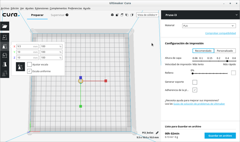
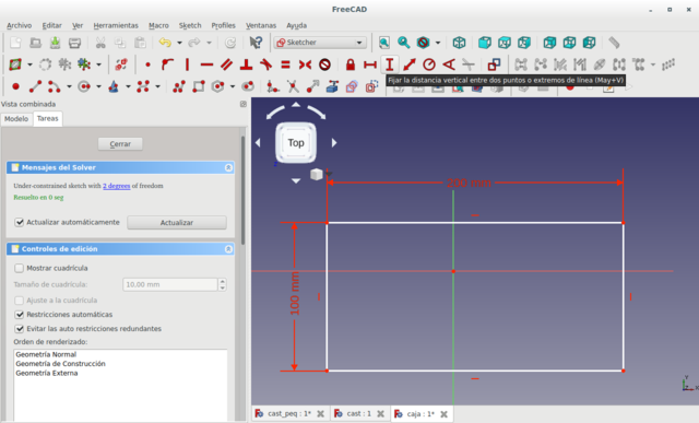
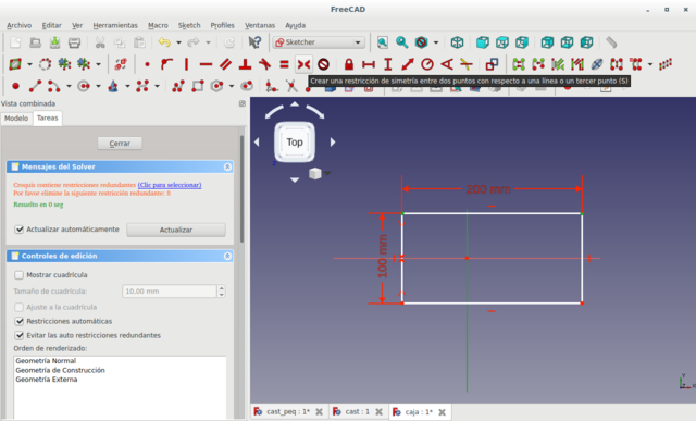
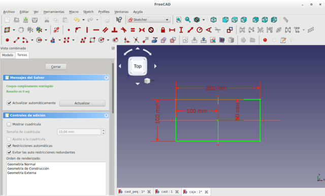
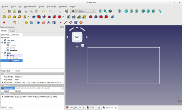
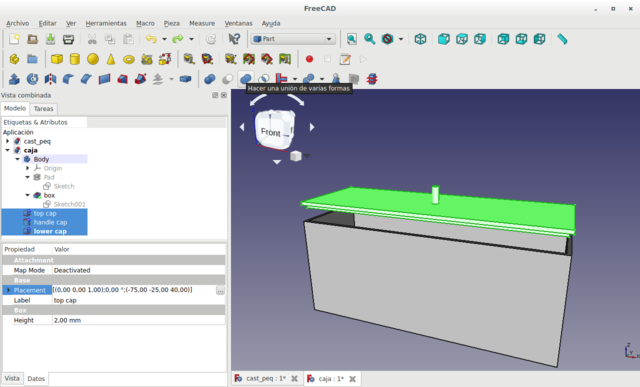
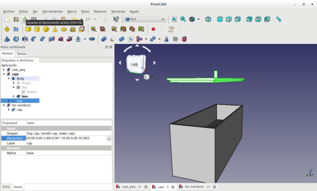
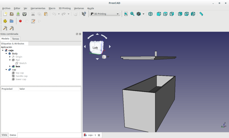
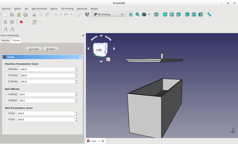
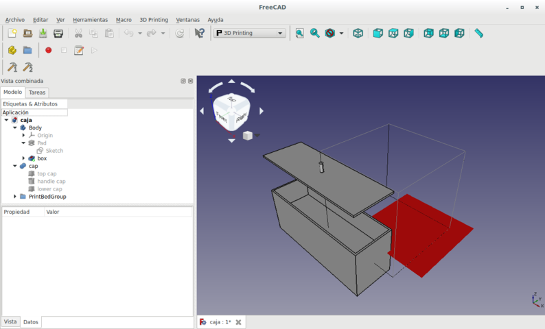
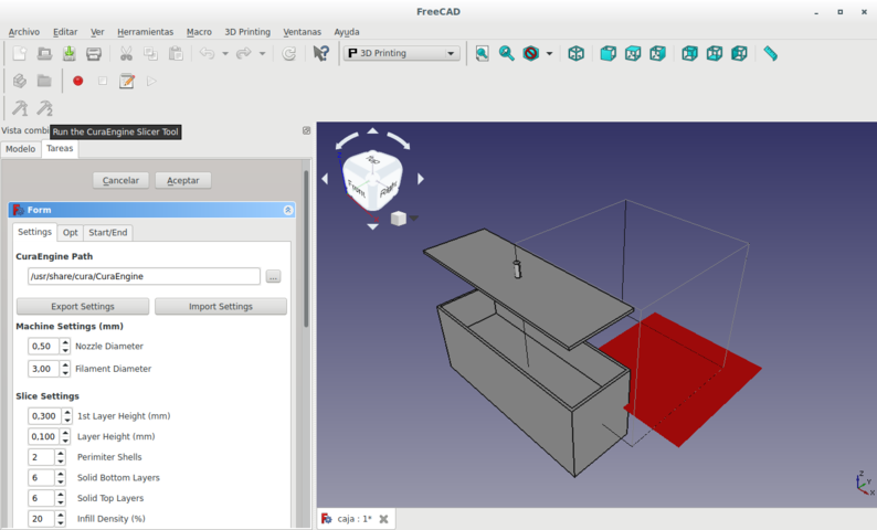
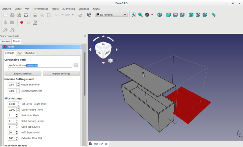
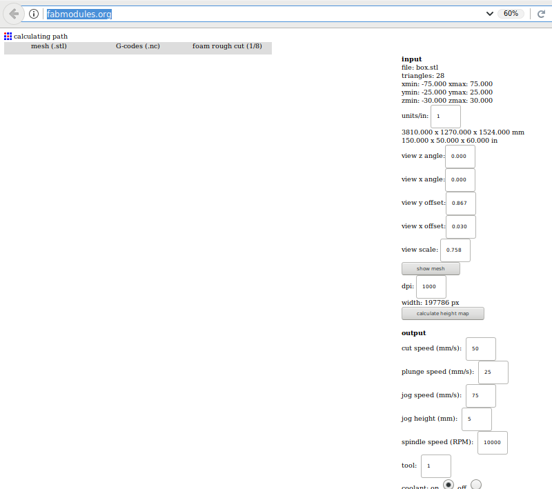
A slicer is necessary to translate 3D images to a 3D printer. The original image must be separated into slices which represent the path that each layer of the end-mill will take in making the figure.
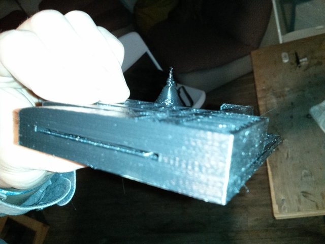
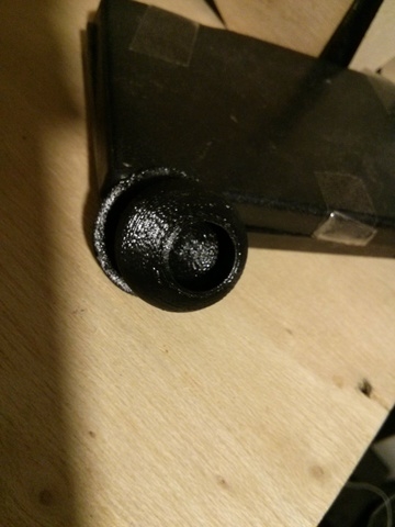
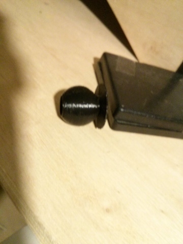
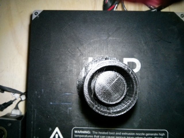
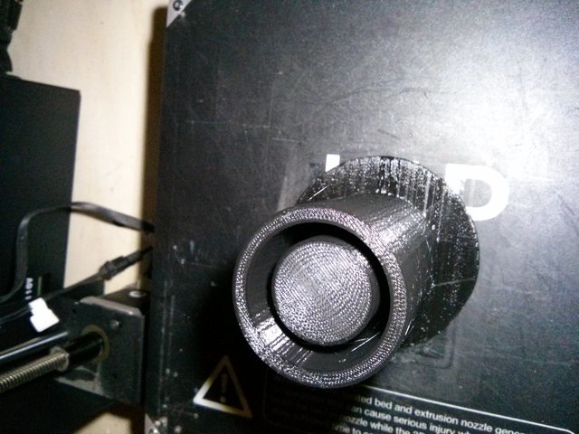
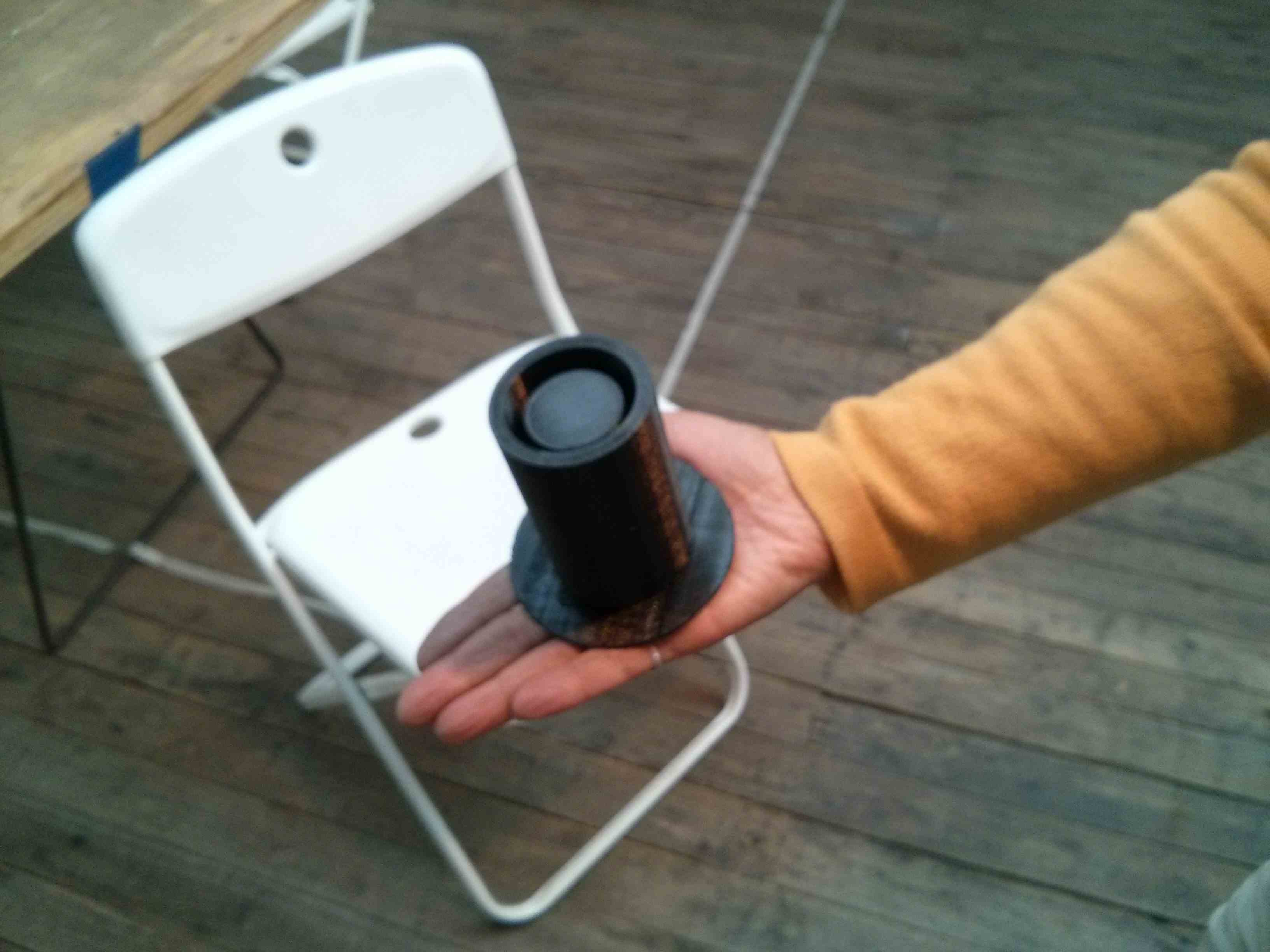
I lost all my files due to a failure in my computer. I had not pushed the files to the repository yet. So I have no files to show. But I could scan myself on a Zen position, closed the holes in my head (pun intended) via software and edited the scanned file to add a base made of a cube, balls and even a monkey. Then I 3D printed the file. Here is the photo of the resulting 3D printed shape.
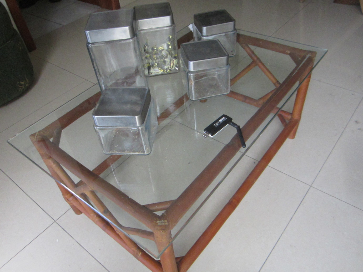
3D mesh of scanned crystal table and jars.
3D mesh of scanned crystal table and jars modified with Xray shadow rendering.