Materials, tools and software
Programmer(Tools)
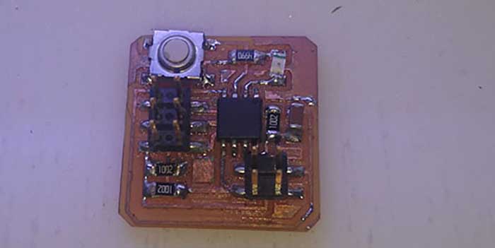
Circuit (Materials)
Arduino(Software)
 |
 |
 |
 |
|---|
Programmer(Tools)
Circuit (Materials)
Arduino(Software)
For group work we made a communication between a plate of Juan with a plate of my Juan's plate can look at the following link.
And the creation of my plate is entered in the following link
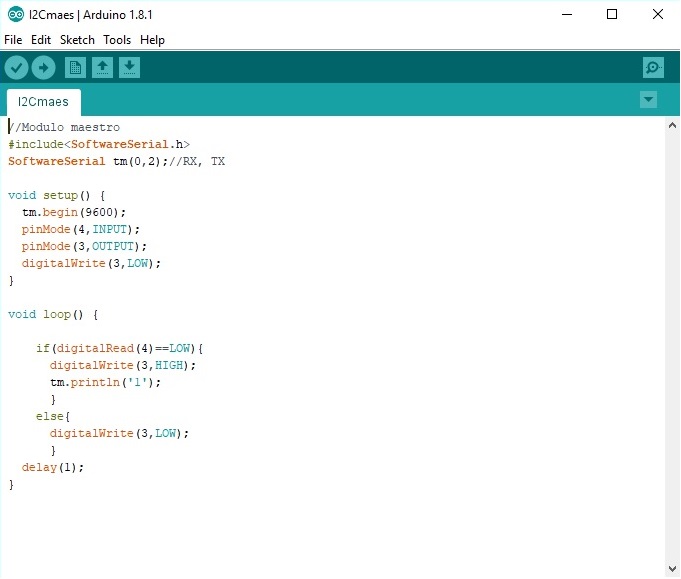
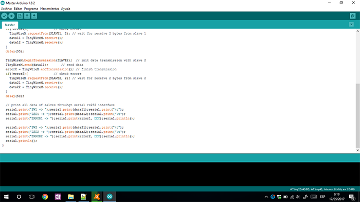
We use the SOFTWAWRE SERIAL library to give a communication for two pins assigned as TX and RX for this we assign this in pins 0 and 2.
Inside the VOID SETUP we initialize the serial at a baud rate of 9600 baud. We declare the pin 4 input and the pin 3 as output giving a low
status to pin 3 with the DIGITALREAD command.
Inside the VOID LOOP we use an if conditional where it will read the logical state of pin 4 in which a button is connected, and it will only enter the process when its logical state is low. Inside the if we turn on a led of pin number 3 giving it a high status and sending information through the communication, the ELSE command is used in order to turn off the led in another condition.
Finally we give a DELAY of 1 millisecond to stabilize the communication between the boards.
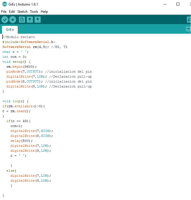
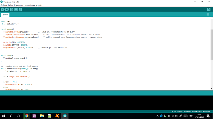
For this program we use the same SERIAL SOFTWARE library, assigning pins 4 and 5 as rx and tx.
A variable C of type character is started.
Inside VOID SETUP we initialize the serial to 9600 baud being the same speed of the master board to be able to establish the communication,
pins 7 and 8 were declared as outputs giving a low initial logical state.
Inside the VOID LOOP we use an if with an AVAILABLE statement to read the serail port as long as there is a value inside the serial, using
the read statement to obtain the data and saving in the variable C. As a next step we compare the variable c with an if for var the activation
of pins 7 and 8 for a period of time and turning off.
We clean the variable C by assigning it an empty entry for any other condition. We use the ELSE command to turn off or give a low logical status to pins 7 and 8.
In this assignment, we make a communication of some microprocessor; this communication can be make by some forms.
In this opportunity, I made the communication by cable.
For make this can see the information of Carlos Moreno
(Click in the name for view more information of your assignment).
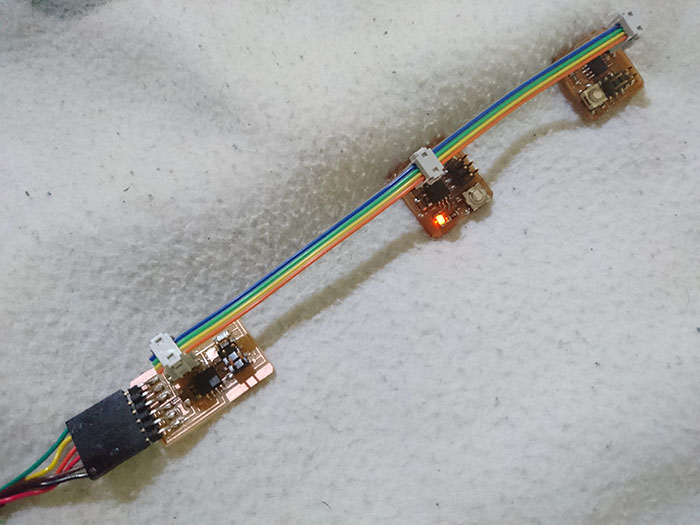
First, make other board is the control of communication, his name is Master
Second, make two boards that turn on a led whit the button, his name Slave.
In this assignment last week is linked because we use its interface also to be able to generate a bluetooth connection with which it will help us for our final project in the vibration system.
For the development of this assigment a Bluetooth connection was chosen since the data interaction is direct and uses simpler
communication protocols since they use the first two layers of the OSI model (Open System Interconnection) DATA LINK and PHYSICAL
LAYER as it can observe in the following image we can see all the layers of the OSI model.
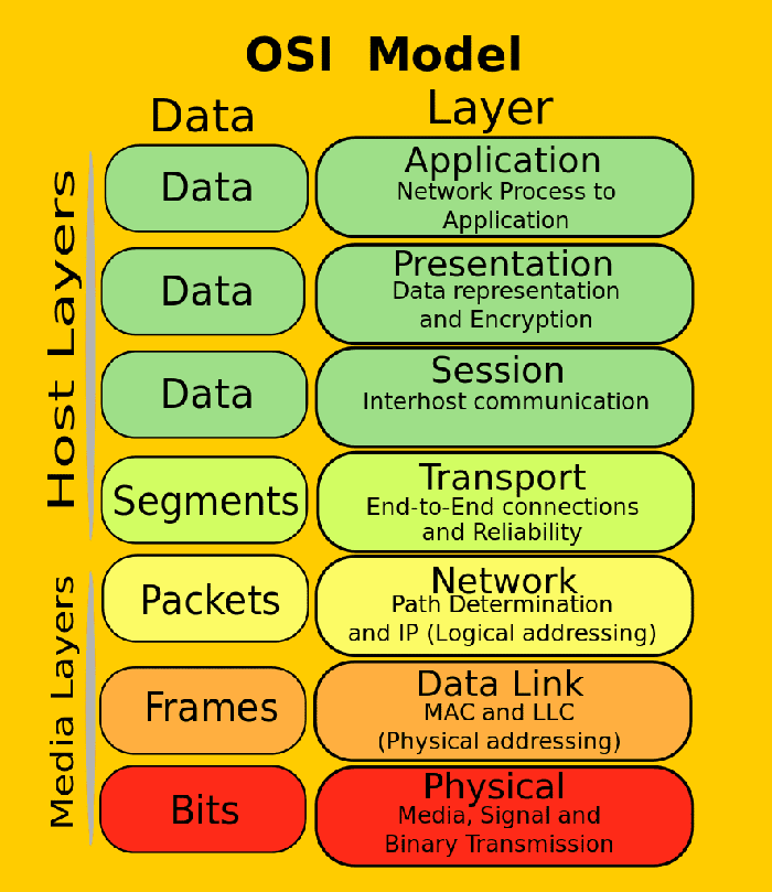
As the image is explained by the DARA LINK layer, they help determine the medium for data transmission, these are handled by frames.
the PHYSICAL LAYER describe the means in our case the smartphone and the PCB with the bluetooth module who are responsible for generating,
activating, maintaining, deactivating physical connections for the transmission of bits from the smartphone to our PCB.
Configurations with which the device can operate:
Master
Slave
Master / slave
For this case we use Master for the smartphone with the command and control the operation of our PCB which acts as Slave fulfilling the function
that commands the master. The Master / Slave configuration will not be used on this occasion.
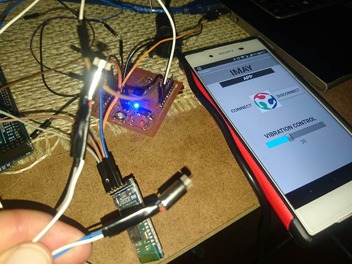
For this practice, you can obtain a wireless communication using bluethoot to control a vibration system using an Android application that was used in the final project. To do this, I developed the design of the PCB, transmission and reception ports, TX and RX ports, as you can see in the following diagram.
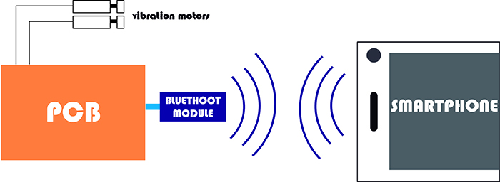
This system I use to generate a compaction of material by vibration of the motors, which are control from an Android app.
Materials:
Vibration motors
Bluethoot module (HC05)
Board designed.
For the development of the plate I base myself on the Satcha kit model which uses the components similar to those I need to use for the development of my plate.
To make this board, I modify the design based on my needs. I remove some headers and change the position of different components
and optimizing the components and position of the pins to my project.
You can get more information about this plate in the following link.
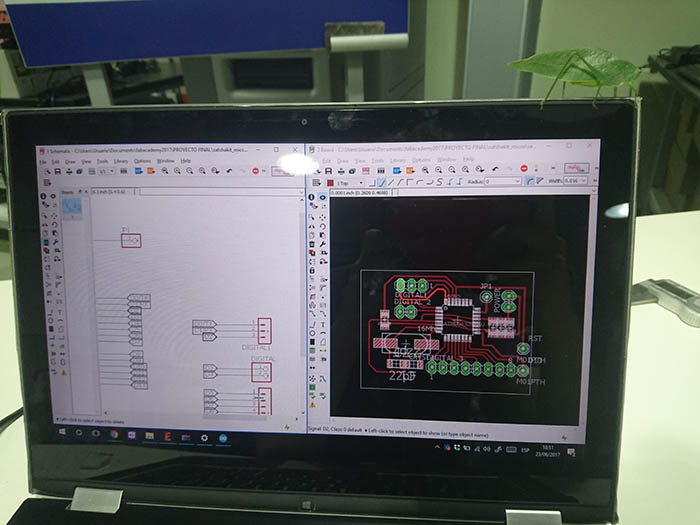
The first step in the EAGLE software in the process of this scheme is to add the components and generate the appropriate connections to obtain the board.
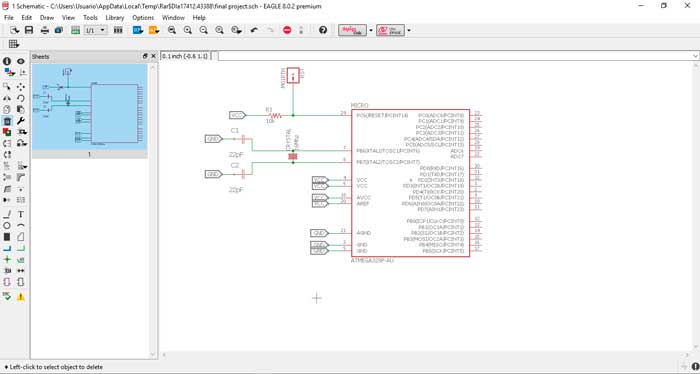
The first step in the EAGLE software in the process of this scheme is to add the components and generate the appropriate connections to obtain the board.
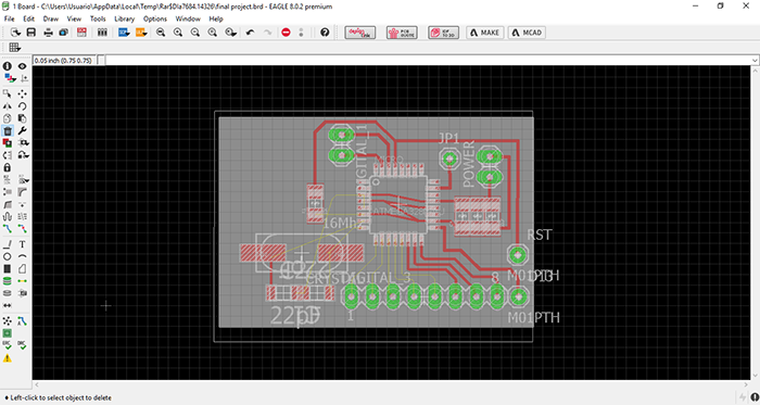
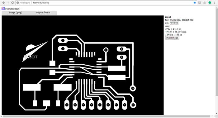
Then we save in PNG format and proceed to import into Fab Modules.
In the web page you can modify the file to process in the machine. In the next image, you can see all the configuration and steps
to make the image process.
Frist select the format and the image.
Second select output format.
Third select drill.
Next Setting point origin.
Next setting for cutting or engraving.
To finish generate calculation.
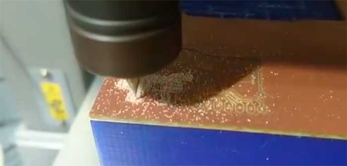
Before starting be sure you have the correct drill 1/64 (traces) or 1/32 (cut) and be sure that plaque fixed to the machine. Once secured. We begin the configuration with the machine starting with placing the starting point of the machine in "X" and "Y" (x = 0, y = 0) and setting with the sensor that is connected because can damage the sensor, before start cutting, verify all the parameters are correct and press "cut" to proceed.
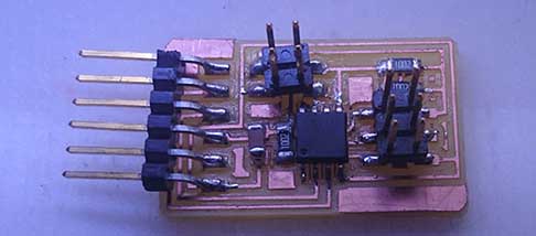
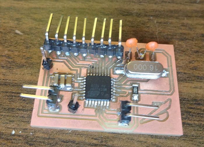
finally weld all the components thus obtaining the final PCB.
Send the value of the app through the bluetooth of the smartphone and the pcb receives this value for its bluetooth module that transforms
it into an analog value which will make the movement to the motors, varying its speed.
Start
-Decalration of variables
-Input and output configuration
-Receive data through the bluetooth module
-Activate the analog pin
-Activates the motor at the specified value
End
This application can control the vibration motors using a slider from zero to one hundred, this slider change the voltage value
to increase or decrease the intensity of vibration.
Based on my experience it was one of the most difficult assignments but it was possible to successfully complete what was requested. I learned about the different forms of communication.