Materials, tools and software
Electronic components (Materials)
Copper Plaque (Materials)
FabTotum (Tools)
Eagle (software)
Fab Modules (Software)
FlatCam (Software)
 |
 |
 |
 |
|---|
Electronic components (Materials)
Copper Plaque (Materials)
FabTotum (Tools)
Eagle (software)
Fab Modules (Software)
FlatCam (Software)
By means of a digital output of the attiny microcontroller an engine is turned on and off by a time control.
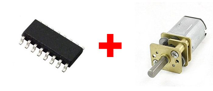
Attiny44
Resistance 4990
Resistance 1001
Led
Motor
Transistor
This process is very similar to the development of last week's project.
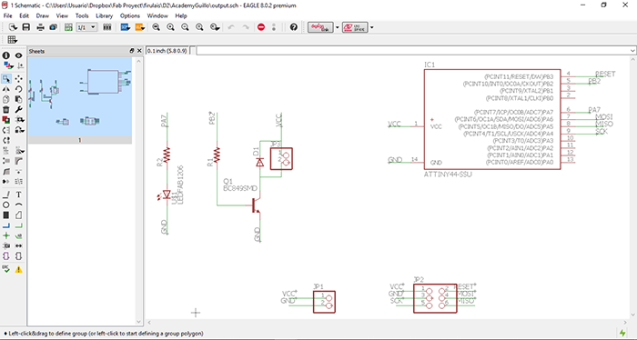
To carry out the design of this board, in the Eagle software we put all the aforementioned components in order to generate
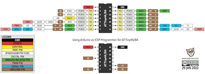
the connection to be able to fulfill this we are guided in the datasheet of the attiny 45 micotrolador. Remembering also to
keep the pins to burn bootloader.
Looking at the datasheet we can find that this microcontroller has eight analog pins and eleven digital pins.
The motor was connected to 5v of the source (vcc) and in its direct emitter to earth, this is ralizo since as we can see in
the datasheet the output of the attiny44 does not deliver the necessary current to feed the motor so it can be burned .
It is understood as the ability of some devices which allow us to be programmed while they are already installed in a more
complex system, this means that it does not need to be programmed before being installed in their interaction system.
Within a wide variety of benefits the main one that we can find is to avoid carrying out the programming process before the
assembly as with other devices instead of doing it in this way we can program it in one step within the performance tests.
Also being the advantage the edition of the same programming in order to improve it.
Most of the devices that use this method use the JTAG (JOINT TEST ACTION GROUP) protocol in which it is used for the sub-module
test of integrated circuits. This is also very useful to identify and correct errors of embedded applications.

The first thing in the software is to create a scheme in which we select the components detailed above and generate the connection
between them in order to subsequently generate the pisatas.
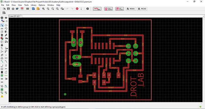
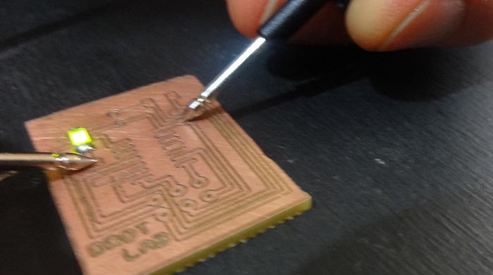
Subsequently perform the generation of tracks tracks and the development of the plate with a led which will help us to demonstrate the proper functioning of the sensor.
In this process we use a machine different from the previous one the Fab totum with its head for CNC machining.
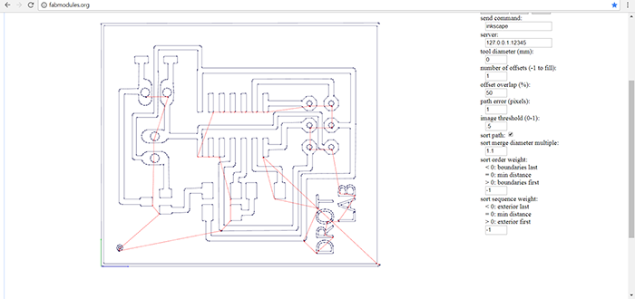
To generate the files we use a program called flatcam which receives the files in SVG formats so we save it in eagle
as a PNG format and in the FAB MODULES we transform it to SVG and in the software it transforms them into NC, format
that supports the machine before mentioned.
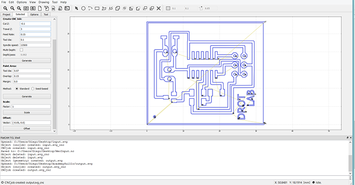
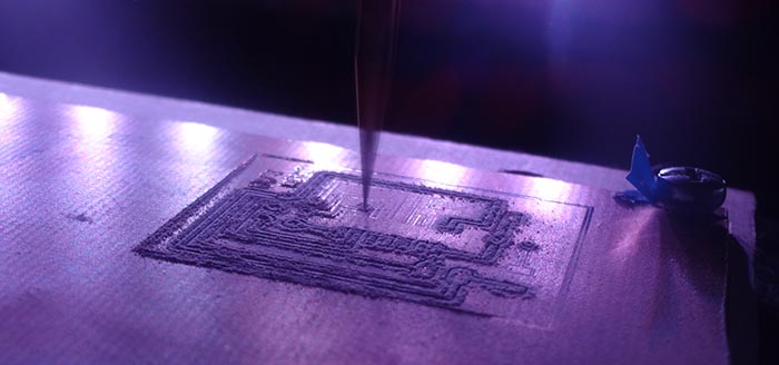
Once we obtain the .NC files we import into the machine software for machining, to accomplish this process we use a ten-degree tool.
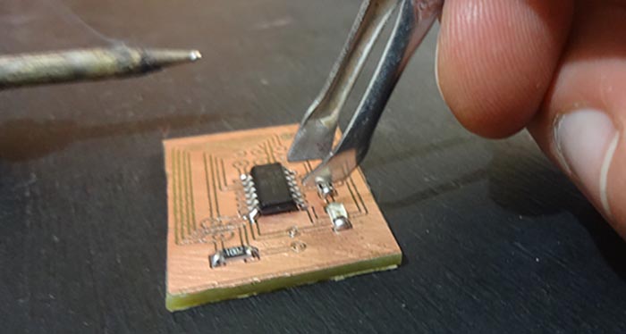
We check that the tracks have been made properly and solder the components.
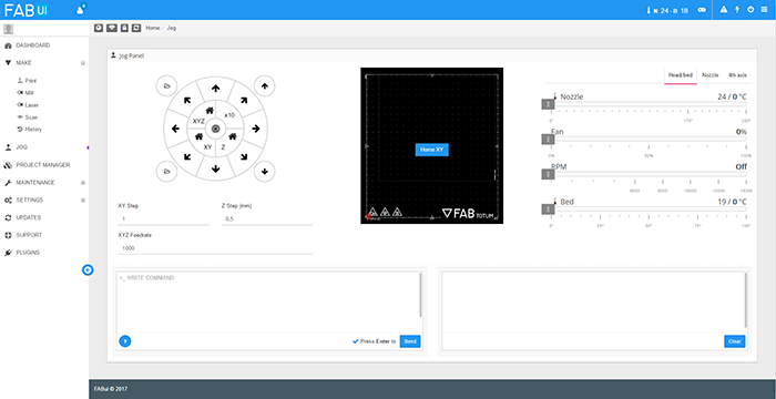
As a next step we proceed to add the file in the machine to machine. we use Fabtotum which uses Fab ui as a driver software, a very
simple program to which you only load the file and calibrate the machine to machine.
As next step we proceed to solder the components on the electronic board.
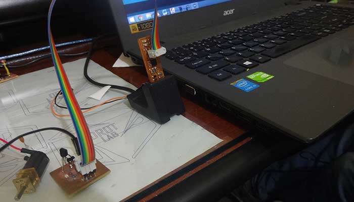
As a first step we burn the bootloaders with the enabled pins of the MISO microcontroller, MOSI VCC, GND, SCK and RESET. Once this process
is created, we generate the programming for the operation of our board.
LOGIC:
START
-DECLATION OF VARIABLES
-CONFIGURE TICKETS AND DEPARTURES
-Energize the pin
-We wait 2 seconds
-We cut energy from the pin
-Repeat from step 3
END
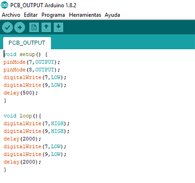
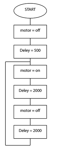
In the VOID SETUP we declare pins 7 and 8 as outputs, as well as the same pins we declare that they start off, followed by a DELAY of 500 milliseconds this in order to stabilize the board when energizing it.
In the VOID LOOP send to pin 7 and 8 by means of a DELAY of 2000 milliseconds after this time elapsed the same pins are declared as off for the same time. Creating a repetitive action of the on and off process.
ATTENTION: IN THE PICTURE OF THE CODE, PROGRAMMING WITH PIN 9 IS OBSERVED. THIS WAS A DIGITATION ERROR, SO THAT THE PROGRAM WILL FUNCTION ADEQUATELY, THIS WAS CORRECTED BY PIN 8 THAT IS DECLARED AND IS THE CONNECTION PIN OF THE MICROPROCESSOR.
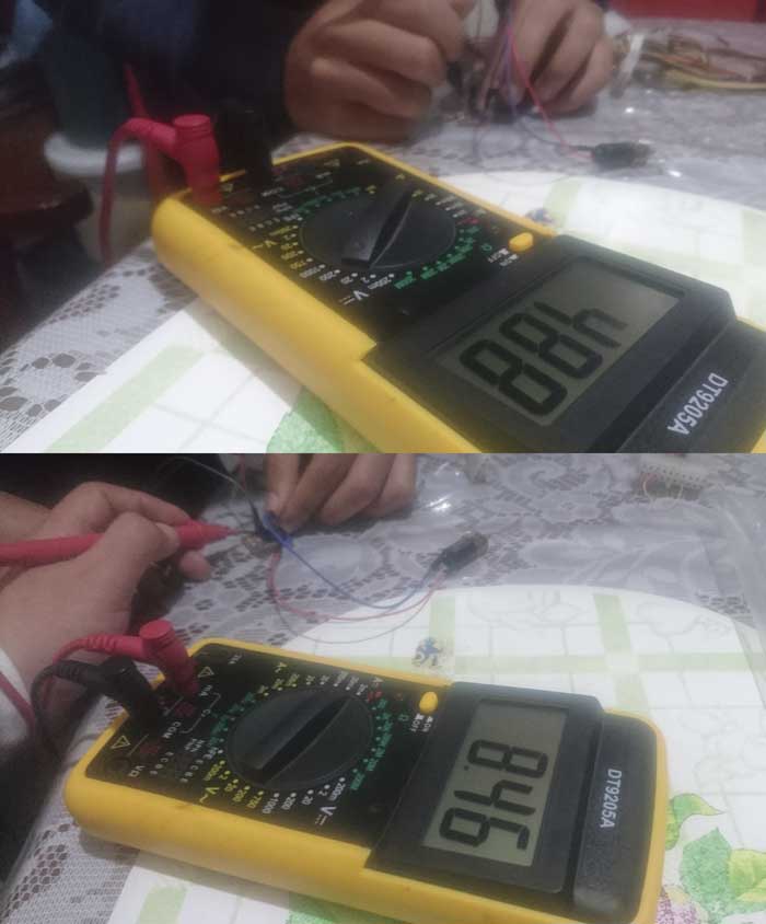
The plate supply voltage is obtained from 4.88v. Giving this value for the recommended operation for the microprocessor work, the current consumption of 8.46mA.
It is due to the connection of the motor, this element for its function needs a greater current consumption for its operation and due to the transistor, the direct
current is taken from the source and not from the microprocessor thus avoiding problems of operation.
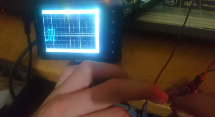
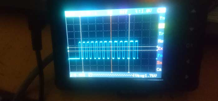
Signal generated by the plate for the motor output.
In this practice perform a prior process to know a little more about the motors which will be used in my final project and
to be able to experiment with them.
It was very useful because this is not my branch but I am very impressed by the link between design and technology.
The use of Datasheet is very important to be able to interpret the components correctly.