For this weekly activity, I am going to design and fabricate a board to control a servo as an output, the system will integrate a AVR Attiny 45 Microcontroller.
Next I will start with the development of the electronic board using the skills in design of electronic boards obtained weeks ago, for this activity it is important to get the following elements:
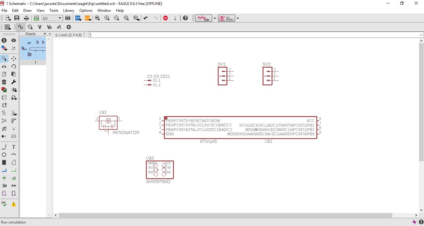
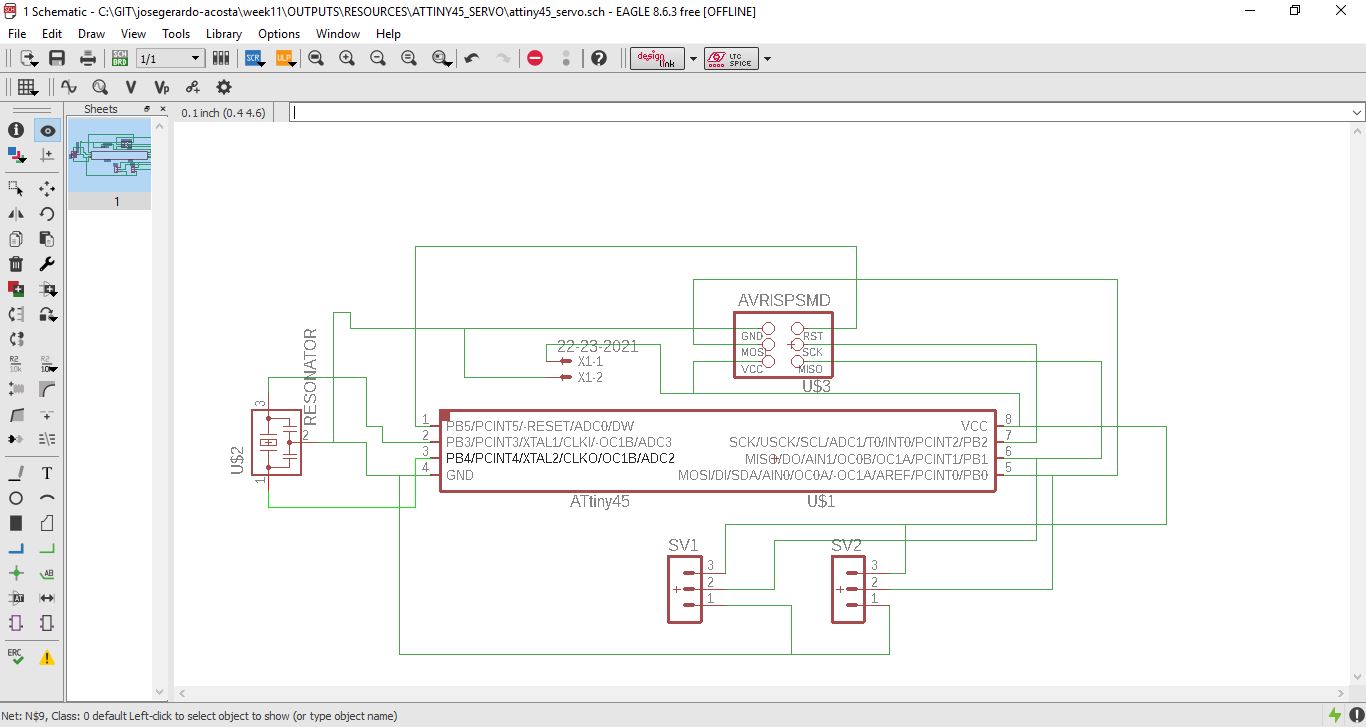
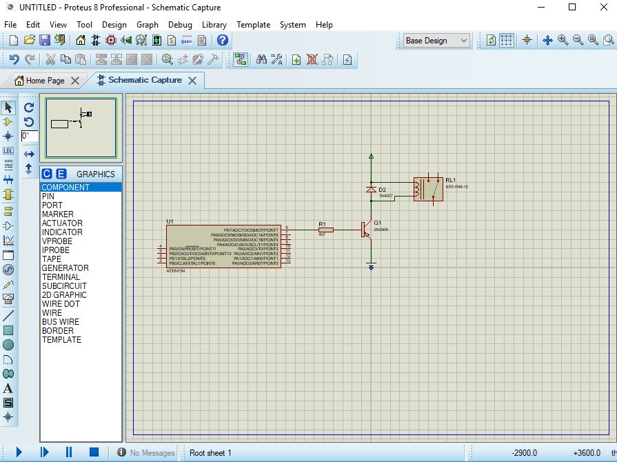
I will start doing the design on Eagle software, to do this, I will create a scketch and then I'll proceed to integrate the different devices beforehand and make the respective connections.
Once the elements with which the electronic board is going to be designed, it is to create the link between the components taking into account design criteria.
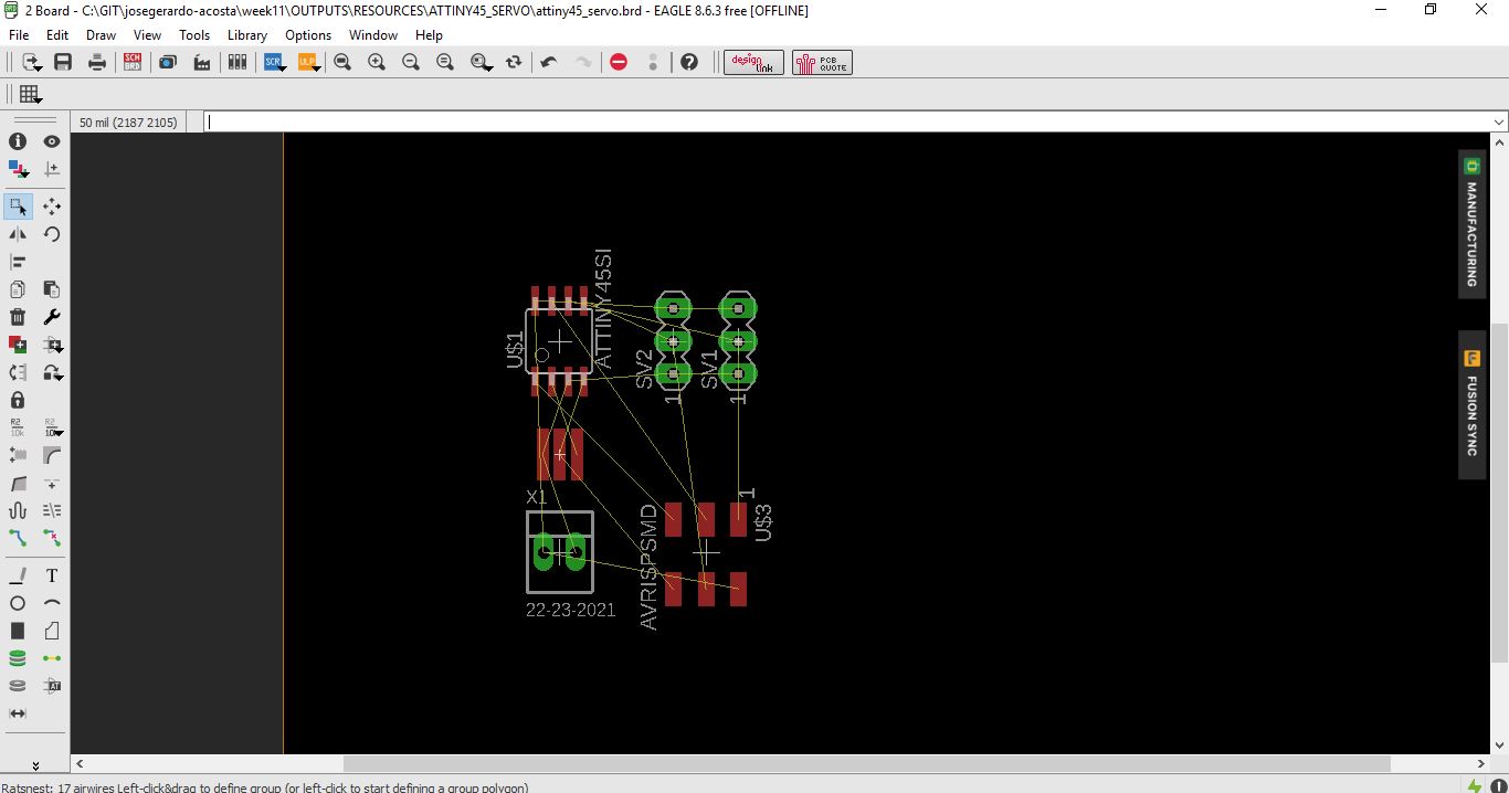
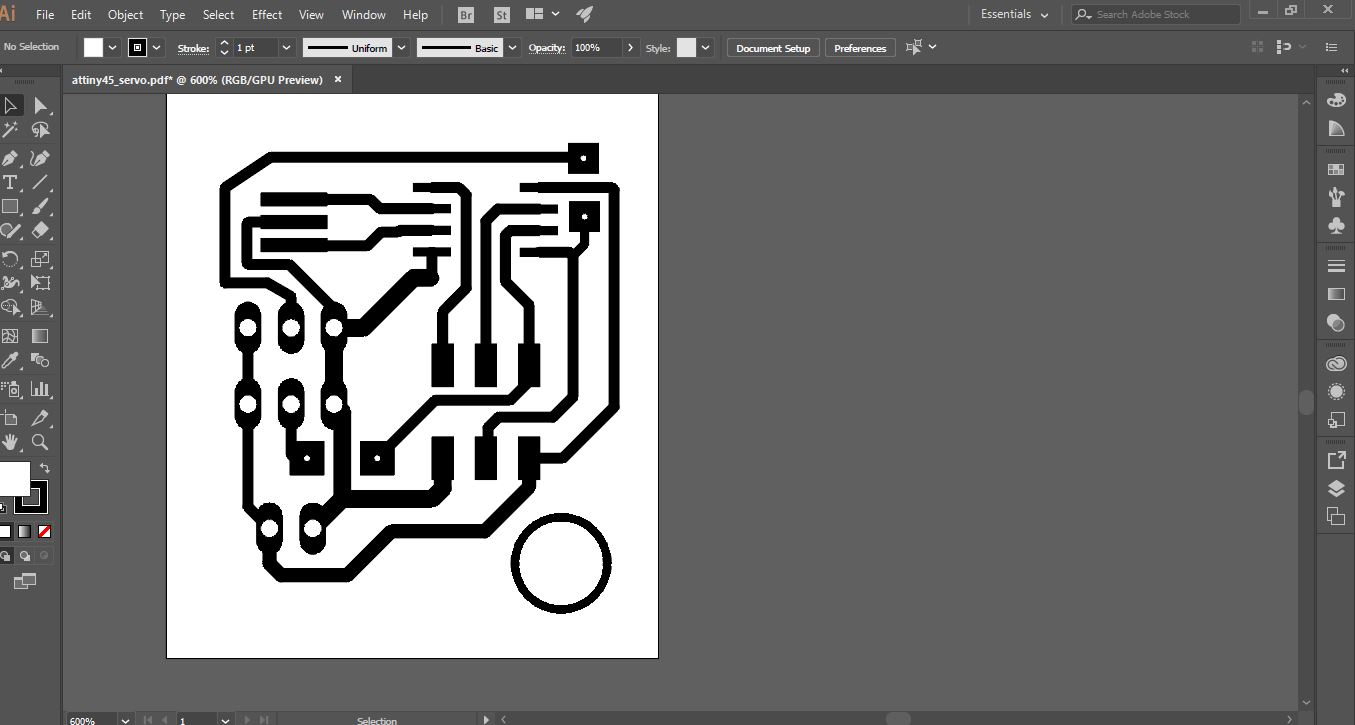
After the activity, we change to the PCB design environment, where I will create the electronic track diagram. If you want to review this chapter you can go to the week 7 that correspond to electronic design.
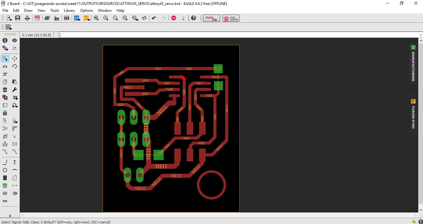
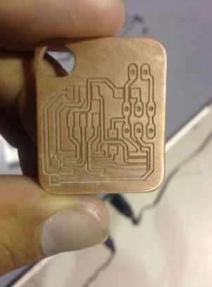
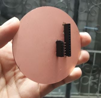
Once the board has the tracks well designed correctly, is important to strat the fabrication. The result of the weekly activity is this:
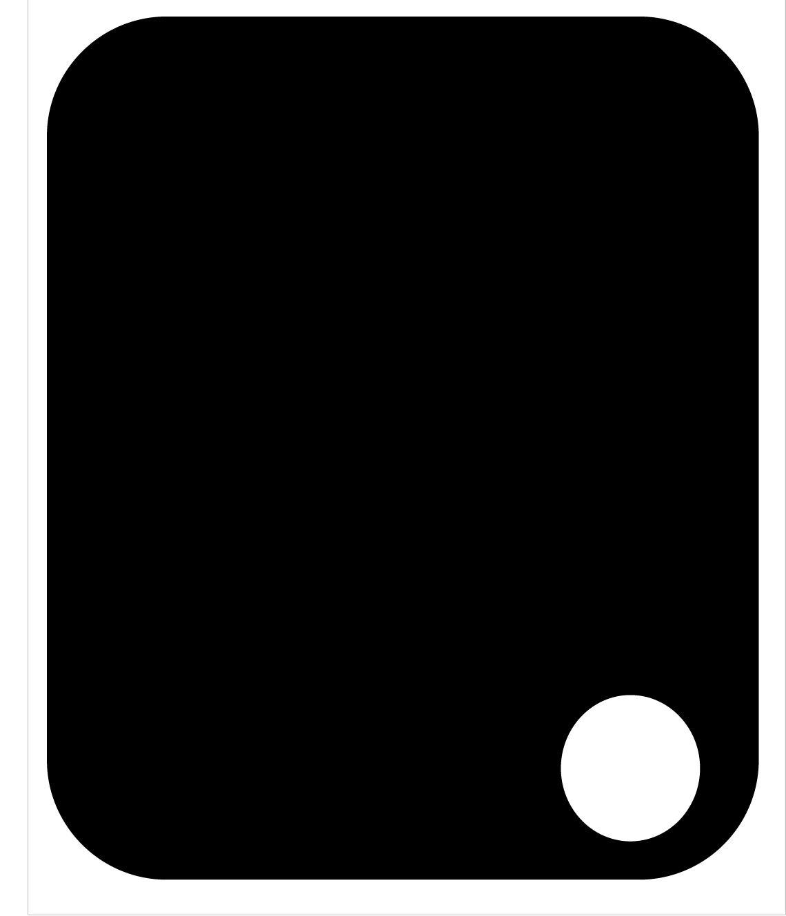
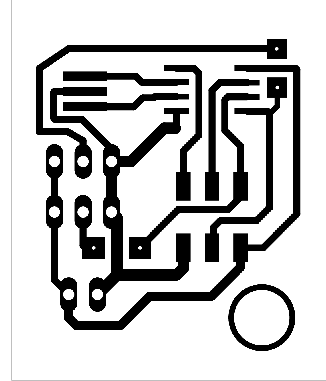
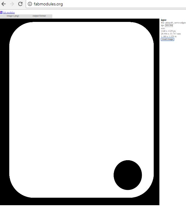
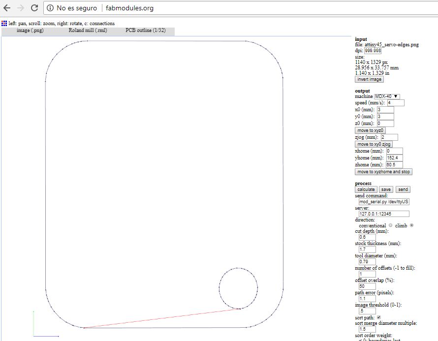
When the file is saved as .pdf, I will open it on Illustrator to modify or personalize the design. I have the following files to export to fabmodules to fabricate.
The roughing parameters for the engraving of the electronic board taking into account the cutter milling of 1/16 with which it will work, are the following:
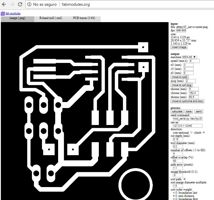
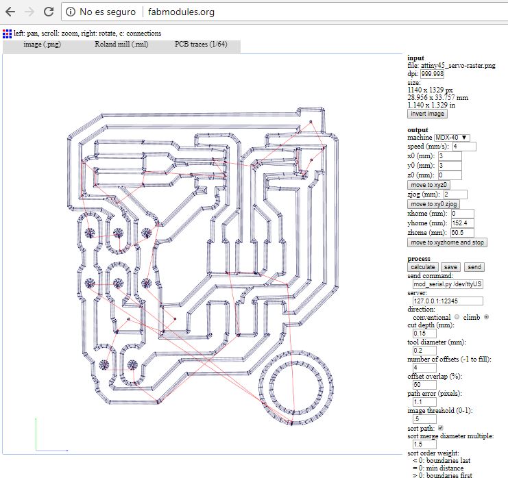
And the parameters for cutting the board are:
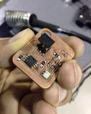
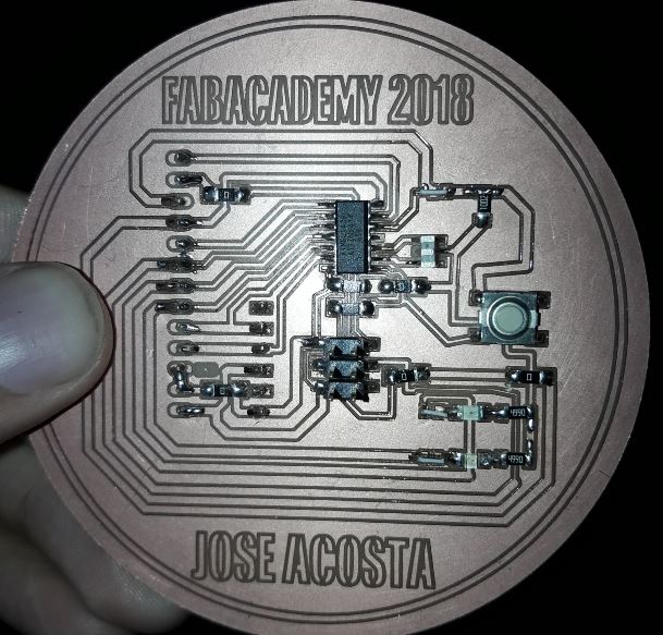
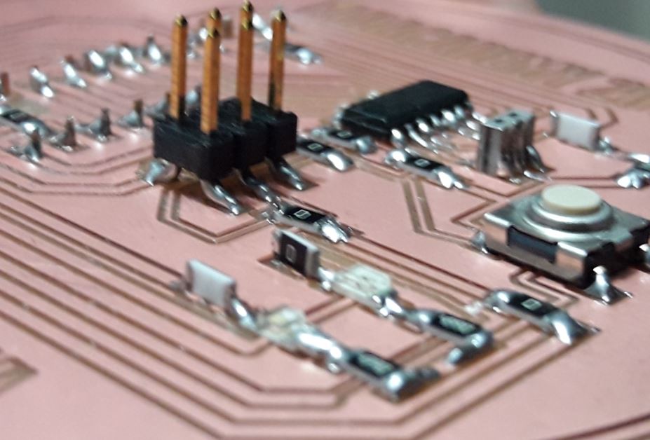
We proceed with the machining of the electronic boards with the assigned parameters, loading the generated .rml files.
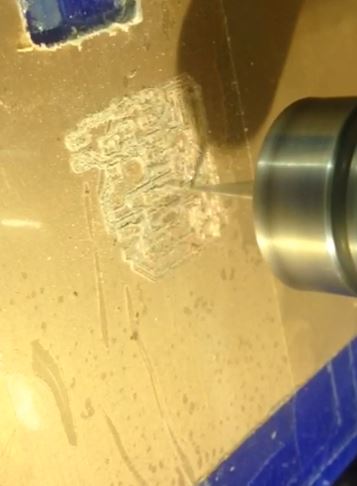
And then I have the result:
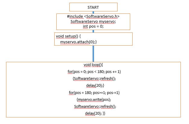
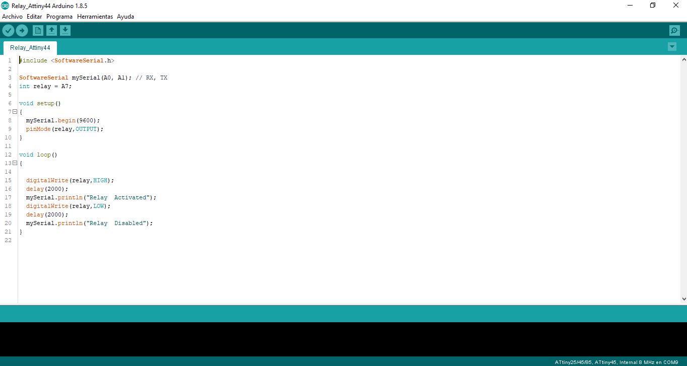
PROGRAMMING
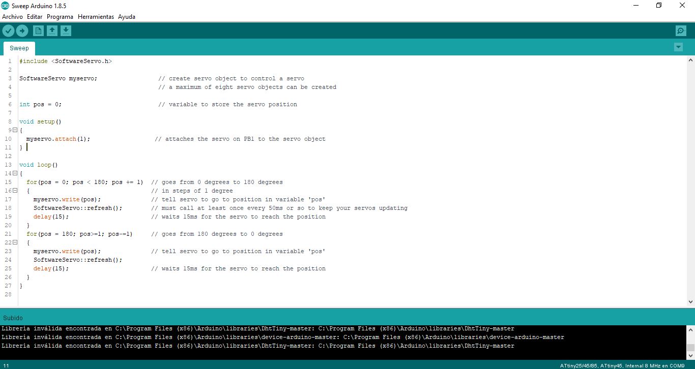
The programming that will help the operation of the electronic board is the following, we must consider that for the operation of Servos it is necessary to install the Software Servo library that can be downloaded here.
Implement and interpret programming protocols
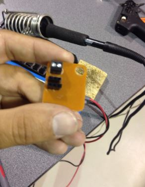
Then, by means of a video, the operation of the plate for the control of a servomotor which is described in the process shown is shown, it is important to know that for the operation of the servomotors an external voltage source with a common connection of GND must be used (Arduino helped us sourcing the necessary voltage).
EXCERSISE 2
As an extra activity, I have developed some exercises to test some actuators on the board that I have manufactured previously and in this way validate its functionality as a board for experimentation such as Arduino.

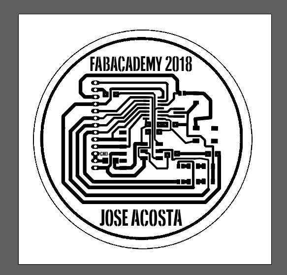
Once the design is done it is opened in illustrator to apply custom designs and images according to the options that the software allows. Once saved will be created two designs, one that corresponds to the engraving of the plate and another to the contour to be machined in the precision milling CNC, we will use FabModules for the conversion of the designs in G-Code, and open it with the machine, it is It is recommended that the engraving surface be totally and strictly flat to avoid problems in engraving and contour cutting
RELAY
It is an electrical device that works like a switch, opening and closing the passage of electric current, but electrically operated. The relay allows you to open or close contacts through an electromagnet, which is why they are also called electromagnetic relays or relays. Look at the following image and we will explain its operation.
Functionability
We see that the relay in the figure below has 2 contacts, one open (NC) and one closed (NO) (may have more). When we put current through the coil, it creates a magnetic field creating an electromagnet that attracts the contacts making them change position, the one that was open is closed and the one that was normally closed is opened. The contact that moves is the C and is the one that makes the other two change position.
As you can see there will be a circuit that activates the coil, called control, and another that will be the circuit that activates the output elements through the contacts, called secondary circuit or force.
The relays can have 1, 2, 3 or almost the ones that we want output contacts and these can be normally open or normally closed (normal state = currentless state).
Electric relays are basically electrically operated switches that come in many shapes, sizes and powers suitable for all types of applications. The relays can also be power relays, larger and used for higher voltage or high current switching applications. In this case they are called Contactors, instead of relays.
For each of the activities carried out it was important to review the operating datasheet of each device to be used, because they have their different configuration. According to the inputs selected for this activity, we have the following datasheets:
In the activity of the servo motor, there was a problem that the microcontroller could not supply the required voltage for the optimal operation of the servomotor, to solve this problem the VCC pin of an arduino that was connected with an adapter as external power was used. the importance of having common GND for the two circuits