Group Activity
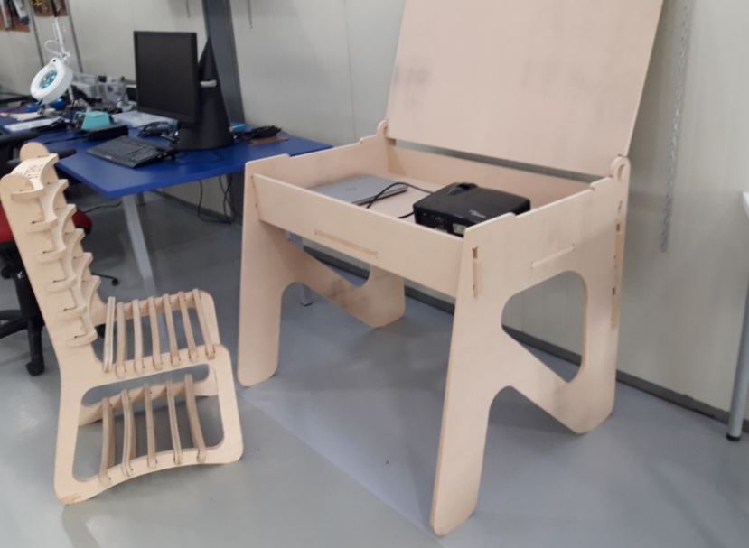
As a group activity we proposed the design and construction of a press kit to know the definition of the milling of the machine, for this, we will use a 1cm thick MDF wood, where in each crack we will make the respective dog bones to optimize adjustments with other pieces.
What's CNC?
The numerical control by computer, or better known as CNC, is a system that allows to control at all times the position of a physical element, usually a tool that is mounted on a machine. This means that by means of a software and a set of orders, we will control the position coordinates of a point (the tool) with respect to an origin (0,0,0 of machine).
The CNC controls all the movements of the tool when we are manufacturing and not only the coordinates, but also the way to move between them its speed and some more parameters.
How does the routing work?
Routing is a roughing process.To this end, a cutter with cutting edges is used, which cuts the material by means of chip cutting when turning.
The CNC Router works with the two axes, X and Y, this allows the cutting tool to move and rough out in both dimensions.
There are many types of tips according to their shape and size. To get an idea of what can be done with them, we present below the complete BOSCH program of professional tips:
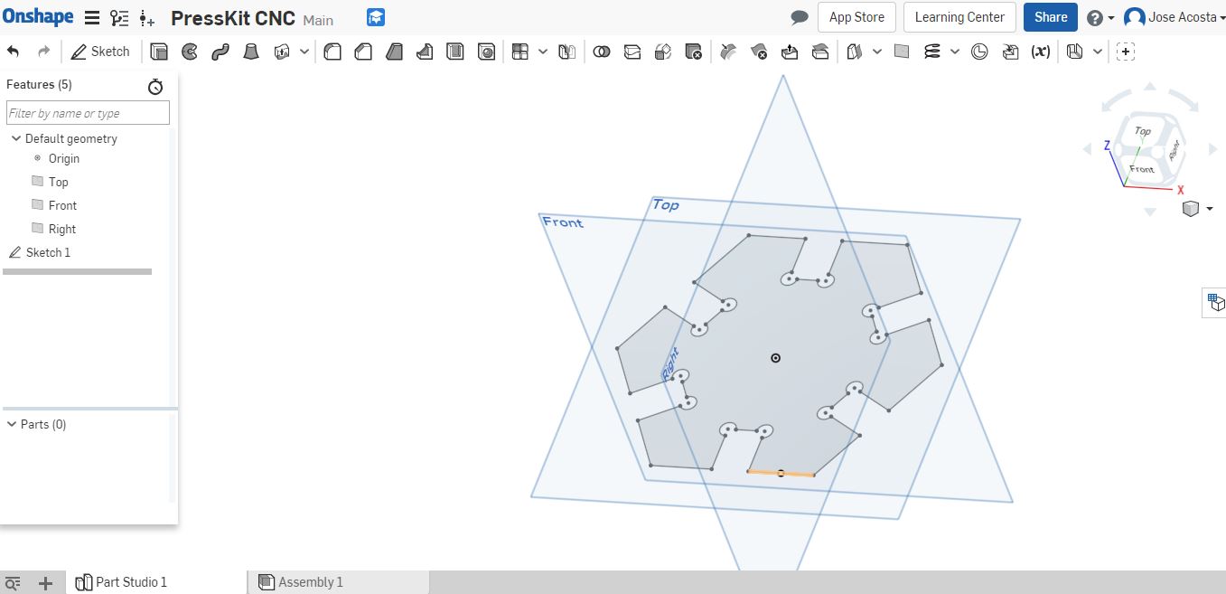
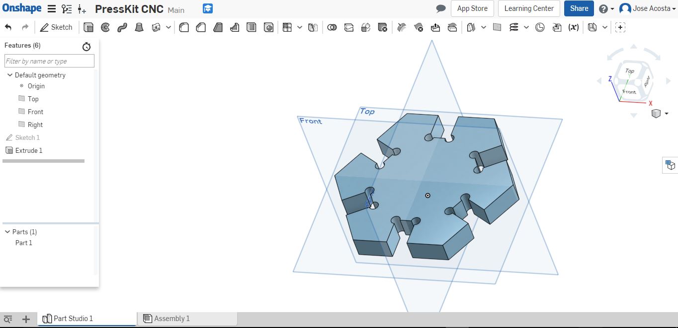
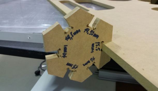
I will start designing our press kit in Onshape, each side of the kit has slots with specific thicknesses that vary by tenths of millimeters so that we know which side is ideal and can match the material to be used.
Here, you have a video of the process
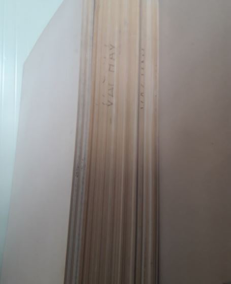
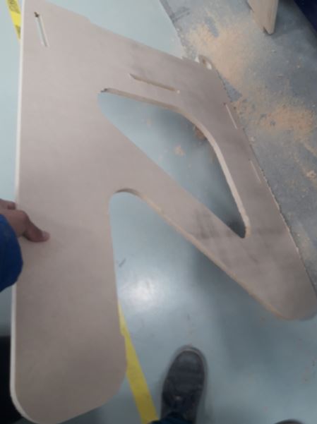
Testing the presskit on the material to use.
Individual Activity
To start with the activity I suggest you draw a sketch according your needs in a piece of paper, specifying the dimensions according the work Space. For the activity I will used SolidWorks.
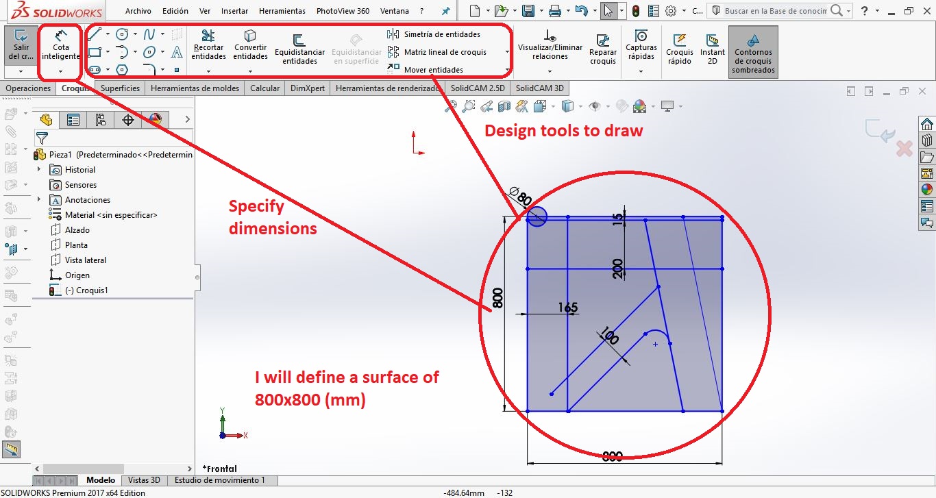
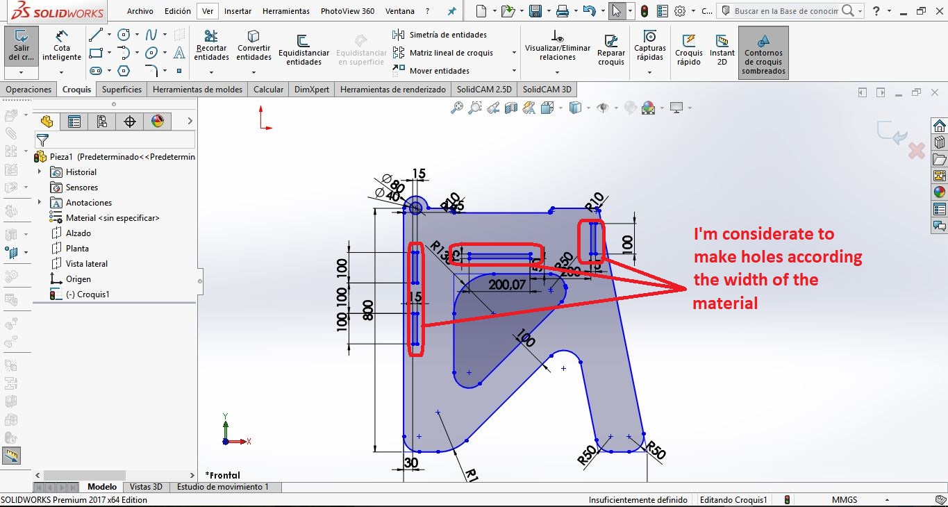
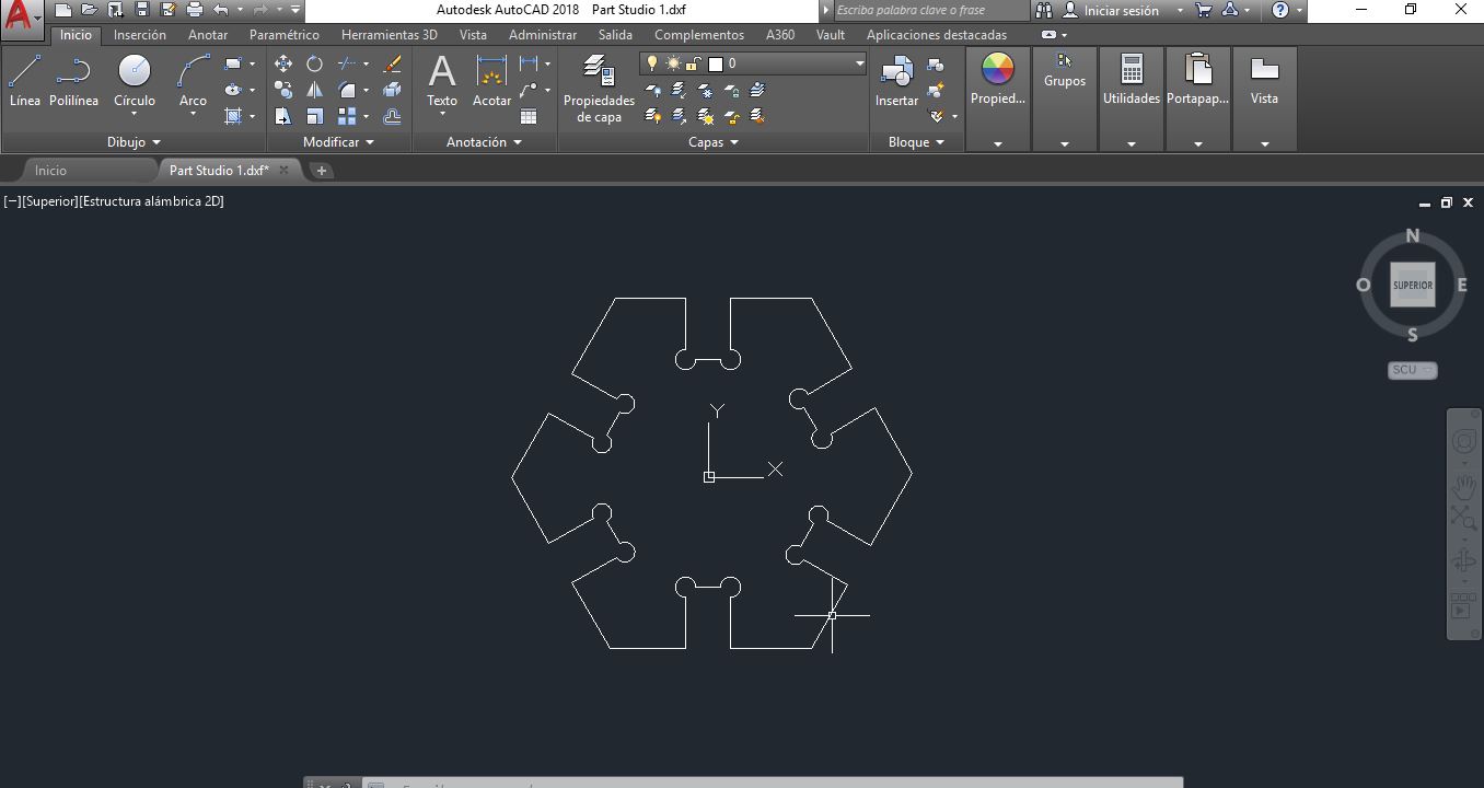
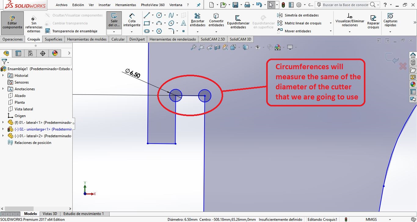
I will use circumferences in the joints to ensure the cuts of closed angles, the circumferences will measure the same of the diameter of the cutter that we are going to use
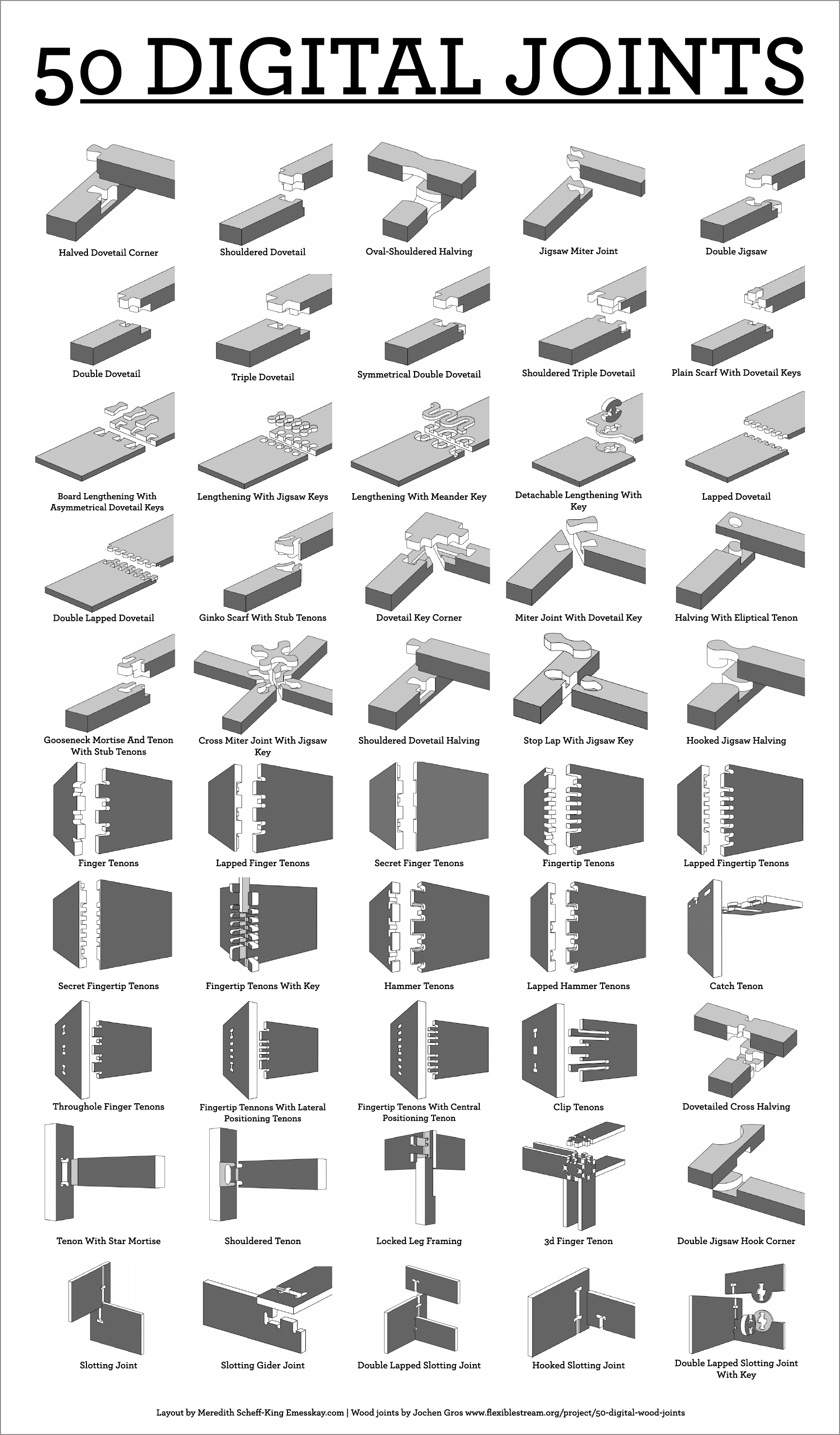
Below I will recommend some ways to join two or more pieces of wood to apply to our designs.
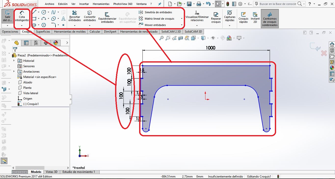
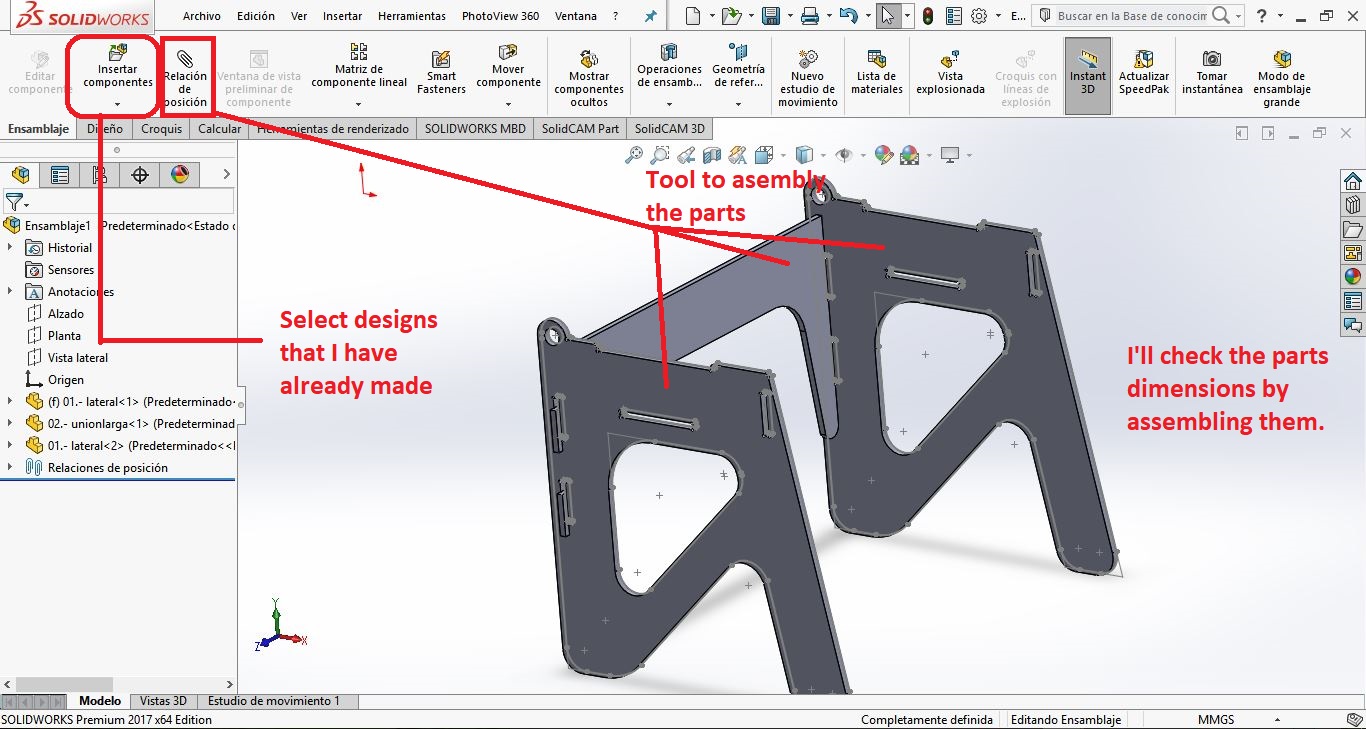
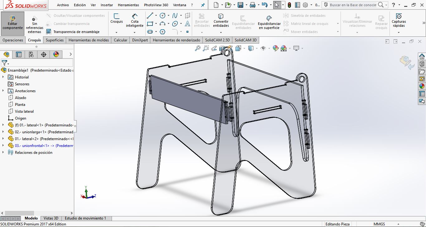
To design a modular correctly, it is important that in some cases we verify the designs within the assembly, in this way any defects can be corrected
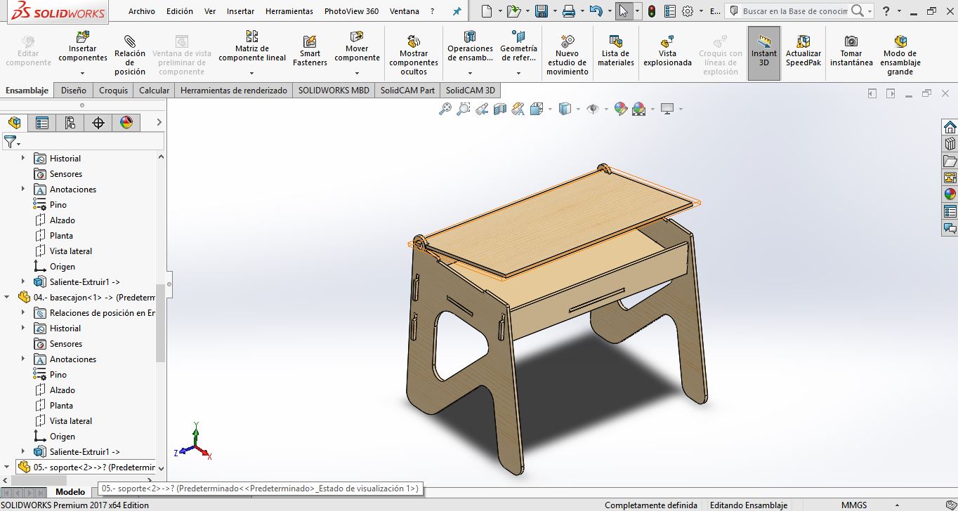
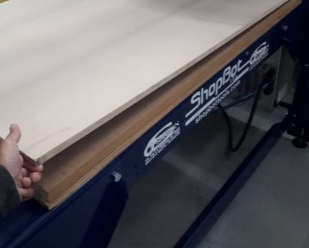
Now, is time to make it real, I start with the fabrication by selecting a wooden plank with an area of: 1,24 x 2,44 (m) and thickness: 15 (mm); the type in this case will be MDF
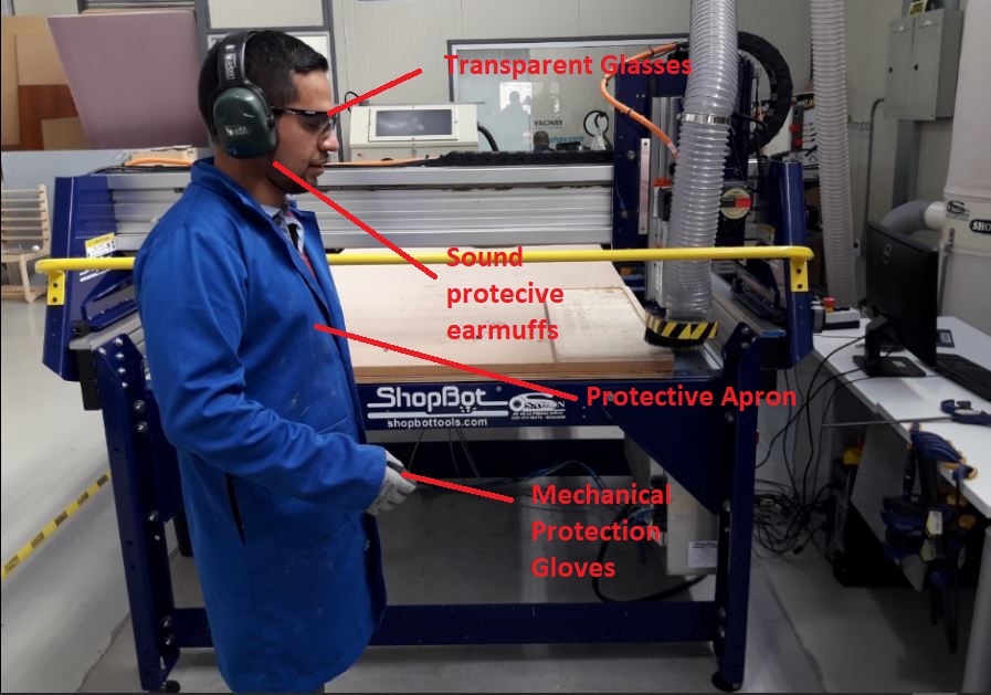
It is important to use personal protective equipment to avoid any type of work accident, so for this activity you should use:
This activity will be developed with a ShopBot CNC Machine, see all the specification here. I detail important parts that make up the machining center
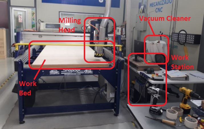
Now, I will describe all the activity:
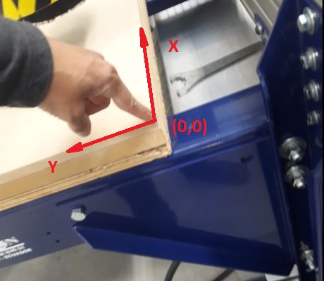
I placed the wooden board on the work bed and place it focusing on the X, Y coordinates of the machine's origin.
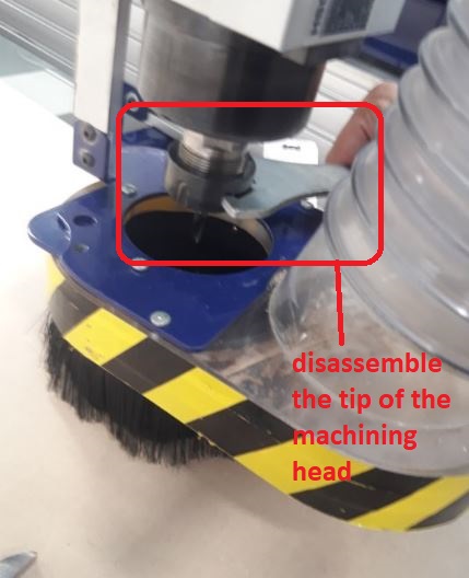
Now, for the development of our prototype we have miller holders and some milling tips that we will use depending on the material and its thickness and the design of the structure.

To do this activity, I will use 1/4 milling tip, so we need to load the tip in the machining head:
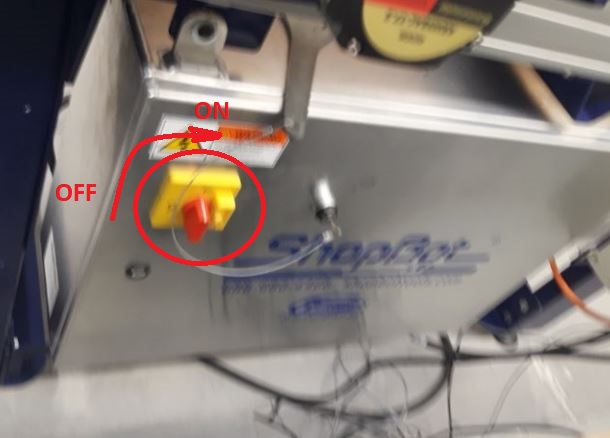
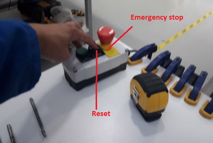
First is important to power on the machine
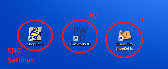
On the work station, we have the programs: ShopBot3 3: it is used to customize the settings of the machine, Vcarve: it is used to prepare the designs to be cut (2D Design), PartWorks3D: it is used to prepare the model to be desvasted (3D Parts).
I'll start opening ShopBot3 to start with calibration and setting origins. Let's press the Reset button.
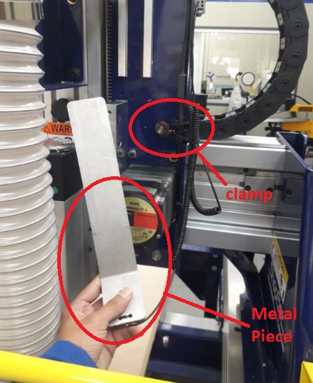
I will use a piece of metal connected to the machining head and a clamp connected to indicate the height level of the Z axis
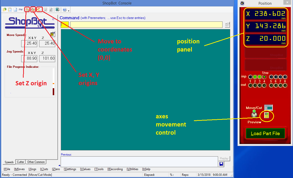
The machine automatically configures the origins in X and Y, by clicking on the calibration button.
To move the machining head we have the following motion control, where we can customize any position in the workspace, either with the movement of the keyboard or by the exact configuration of the digiting positions.

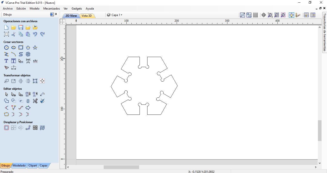
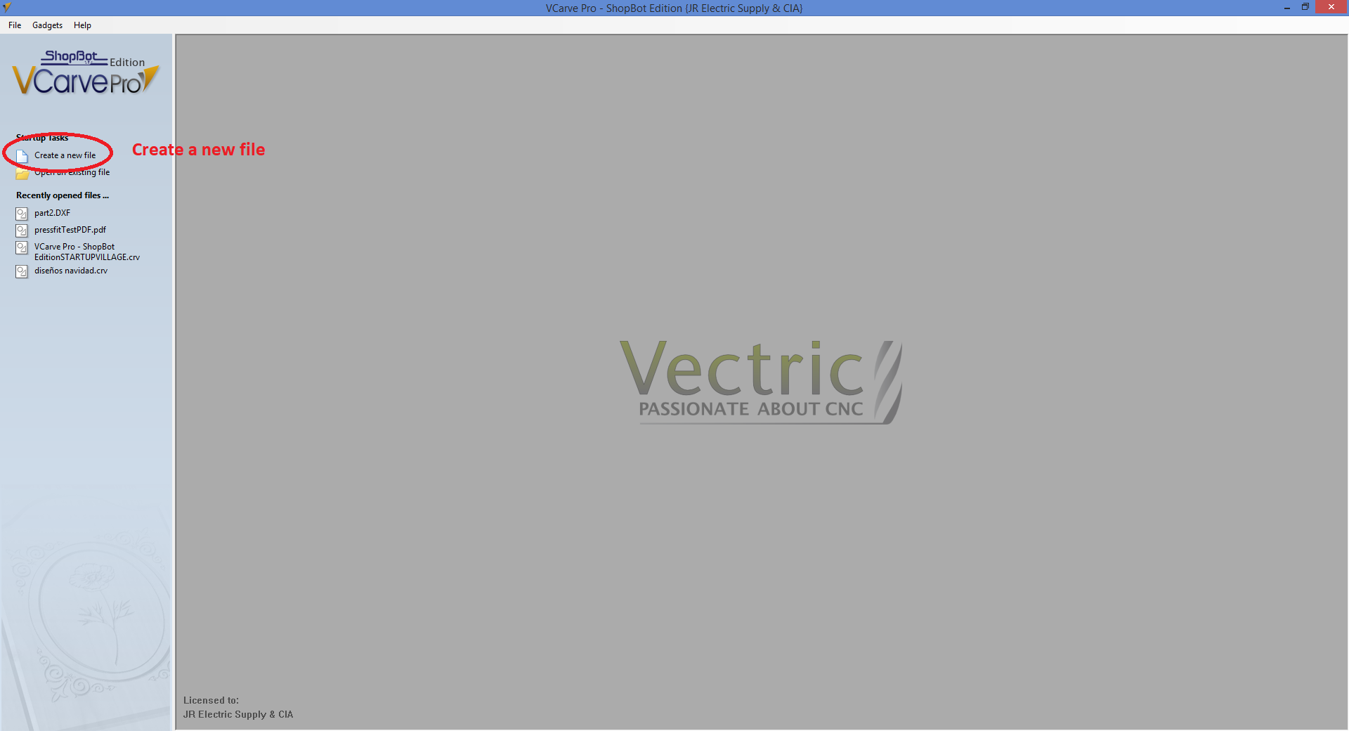
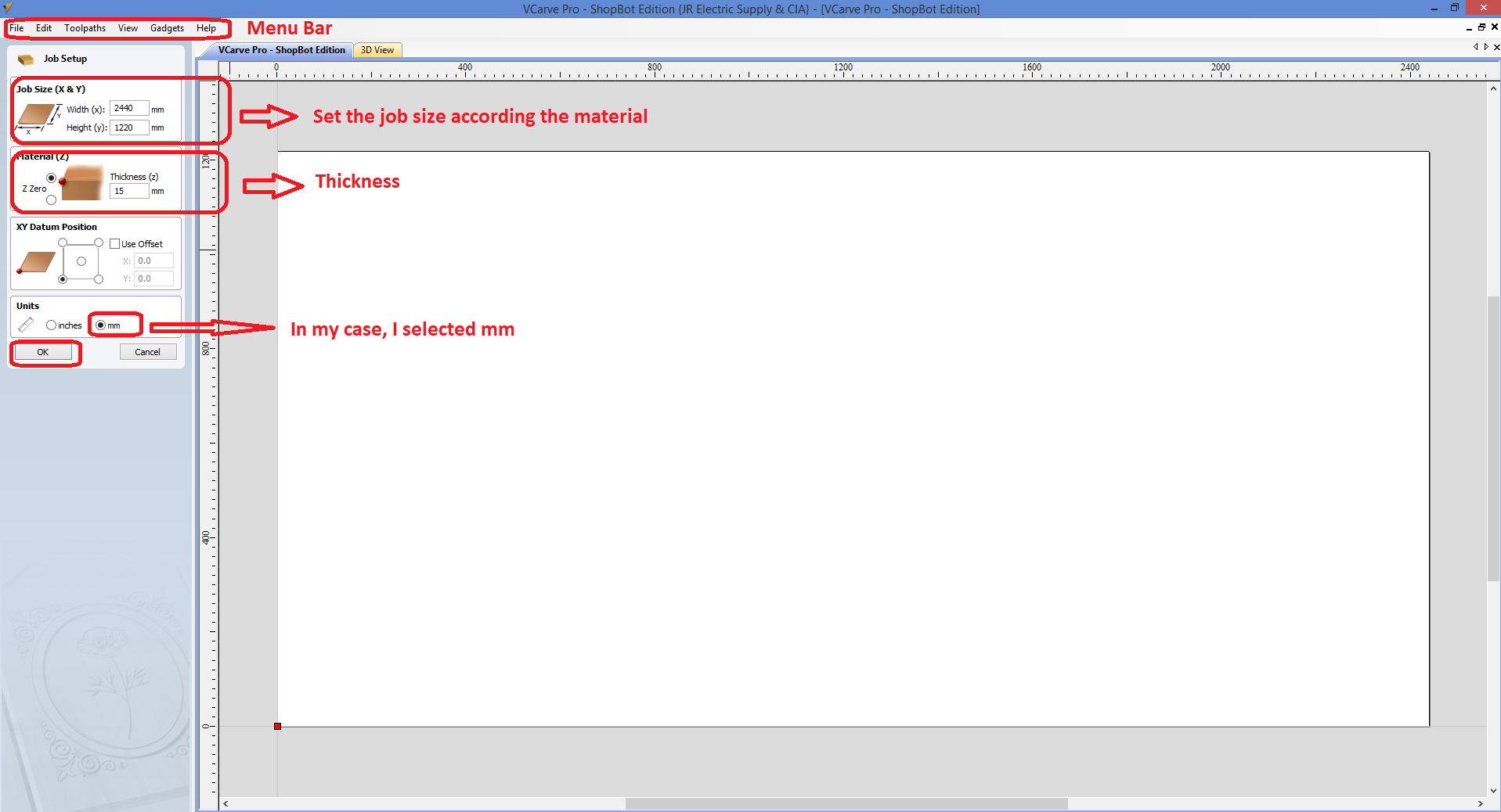
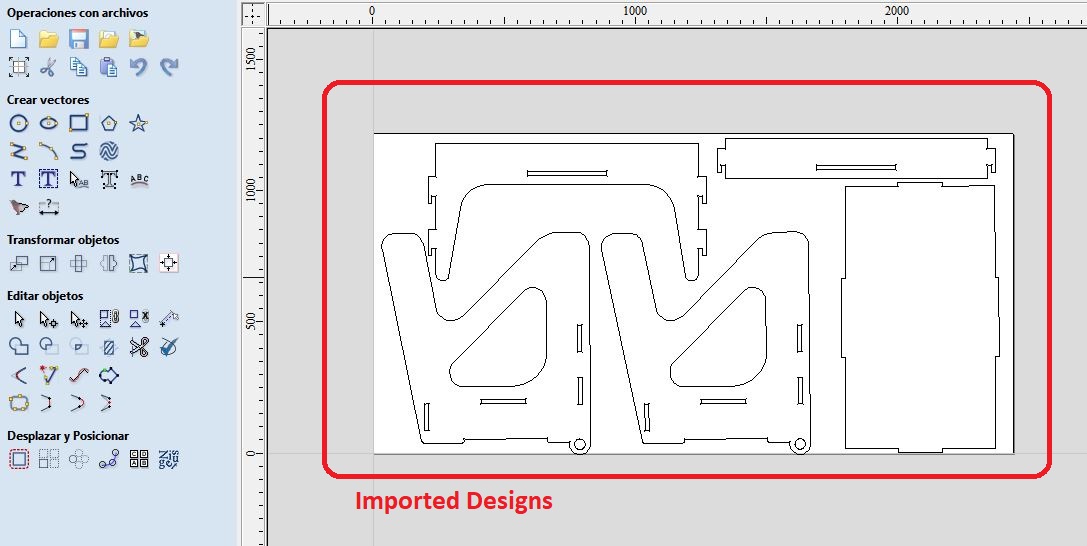
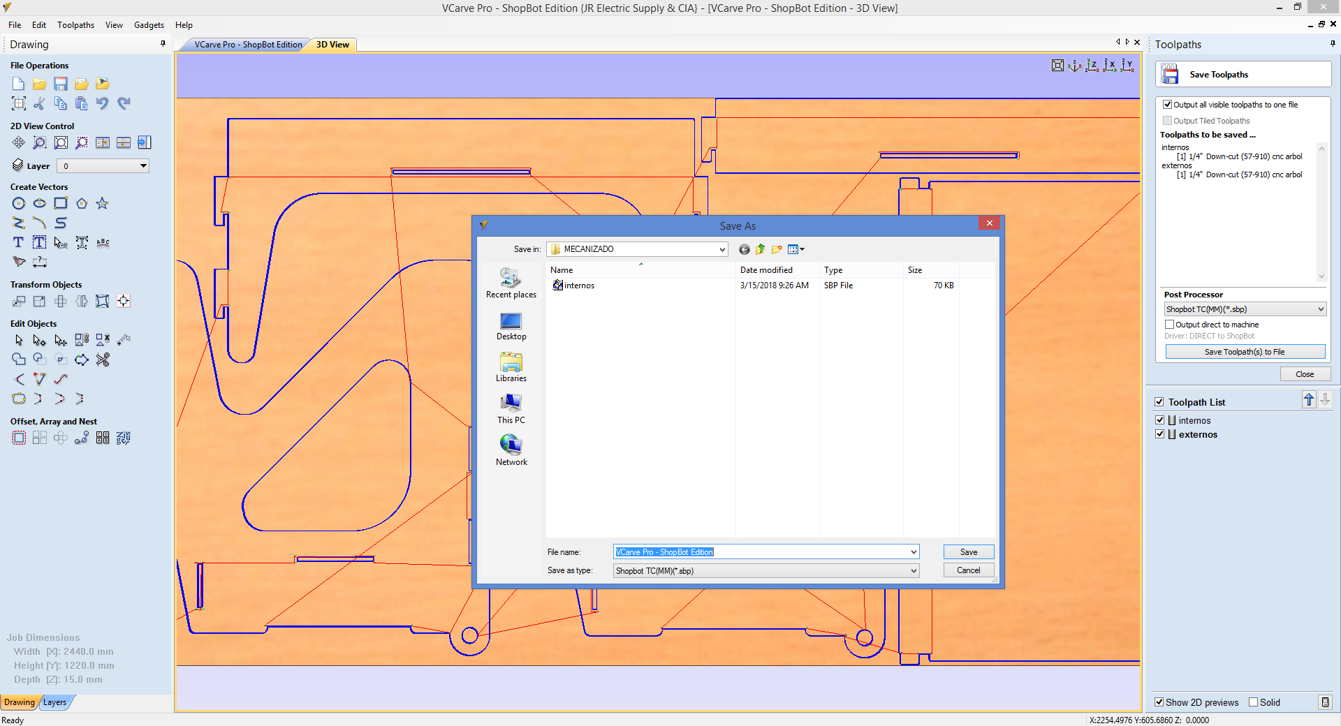
To fabricate the parts let's open Vcarve, especify the job area, and the thickness, and then import the designs
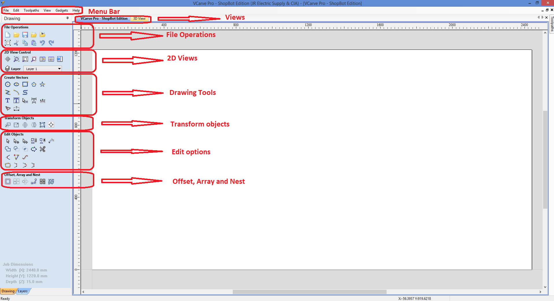
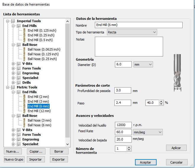
I will select the cut option, then I will configurate some cutting parameters
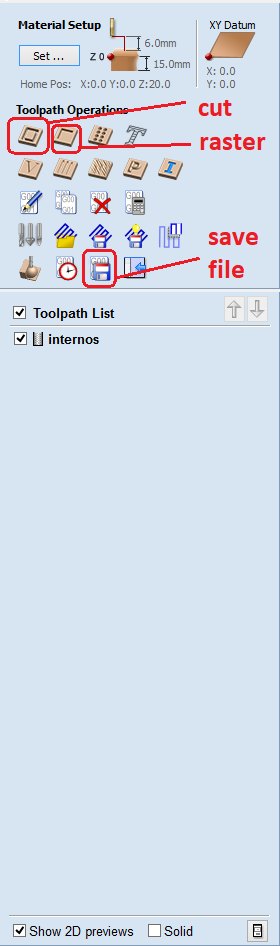
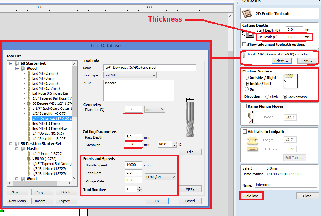
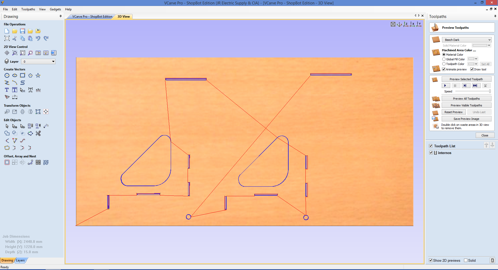
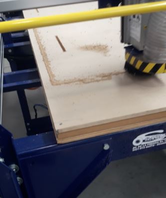
First, I focused on cut the internal holes of the parts, so is important to define the cutting depths, in this case i will confugurate according the material thickness. For this activity i will select 1/4" milling tip and set the pass: 3mm, spindle speed: 14000rpm and the feed rate: 5 inches/sec, finally specify the machine vector with an inside trace.
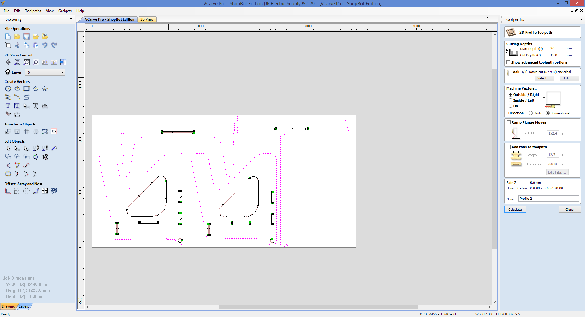
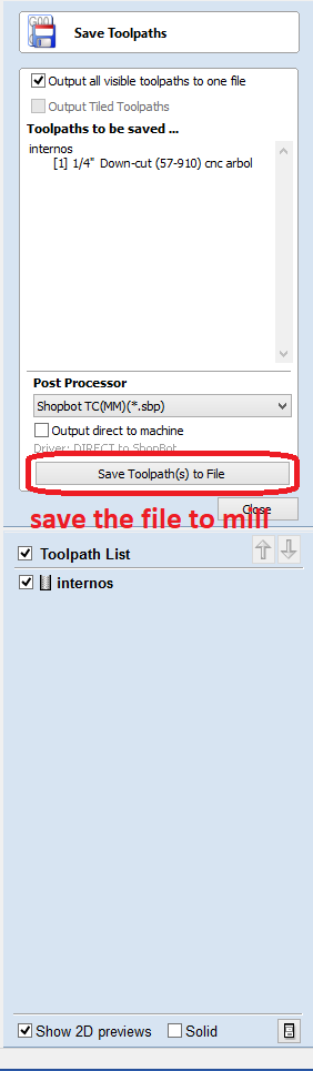
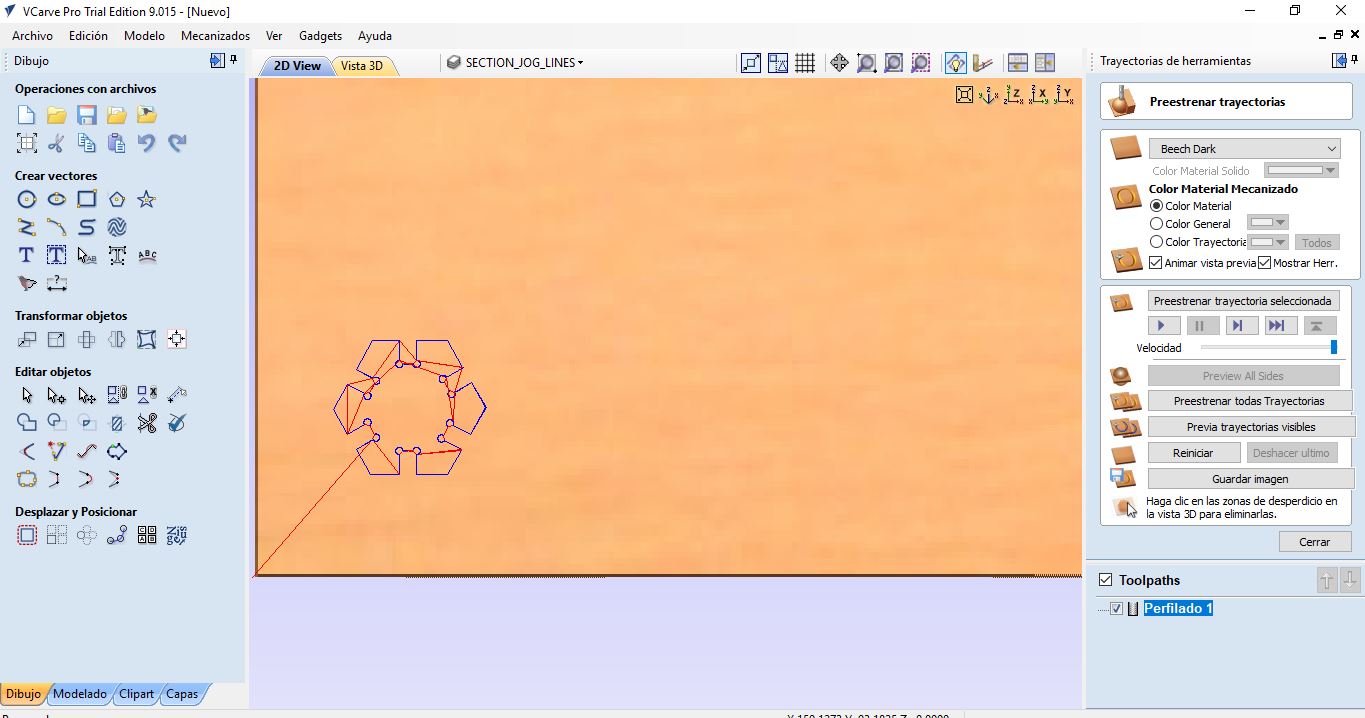
Next, I repeated the same procedure but in this case i will select external vectors to trace. Then I have this:
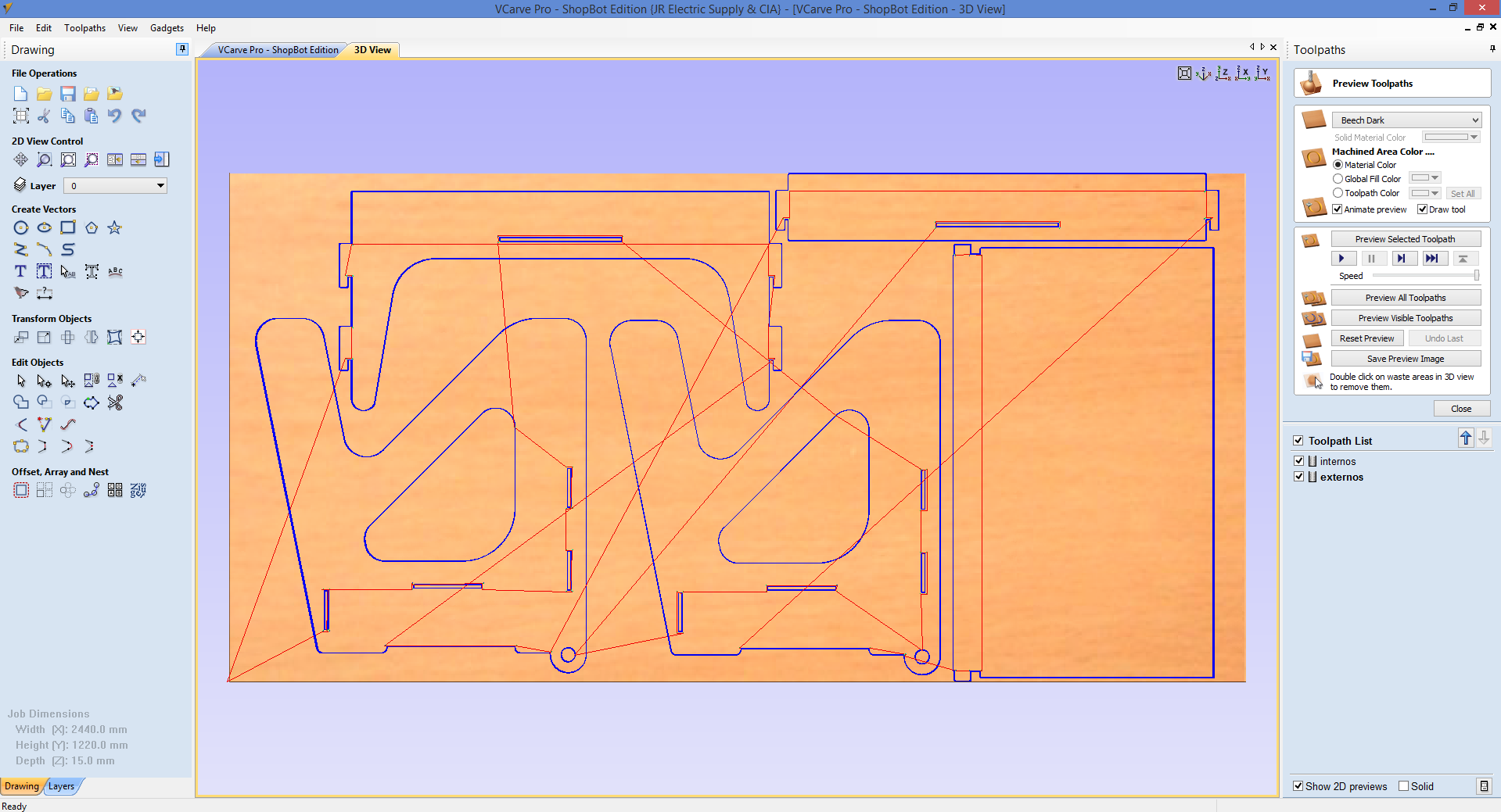
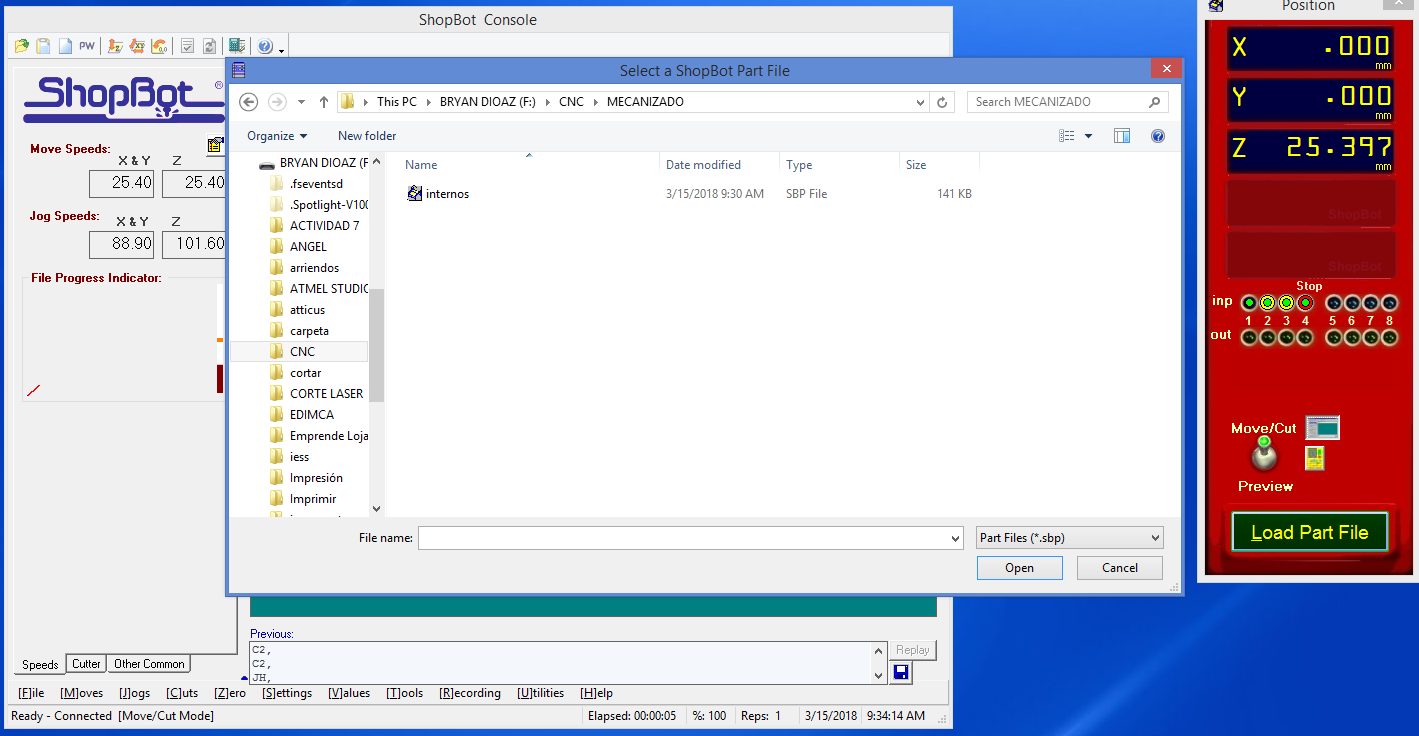
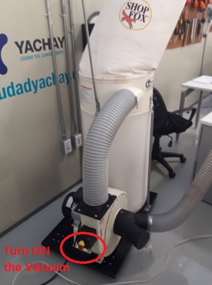
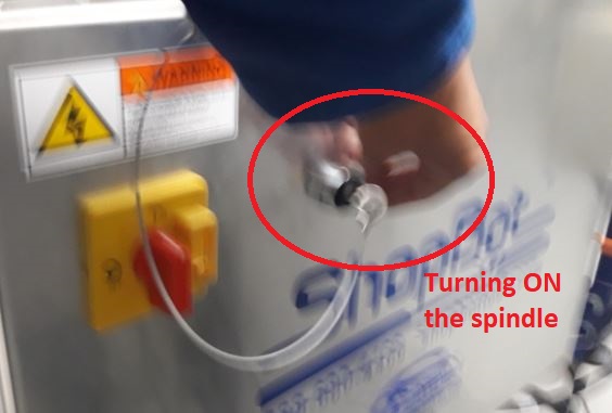
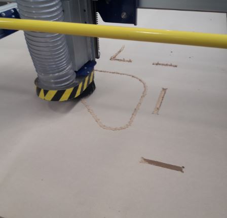
Continuing the procedure, I will open the file from ShopBot software, then i will turn on the vacuum cleaner and the milling tip
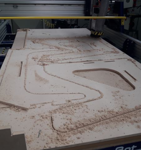
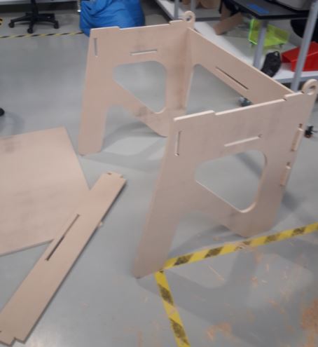
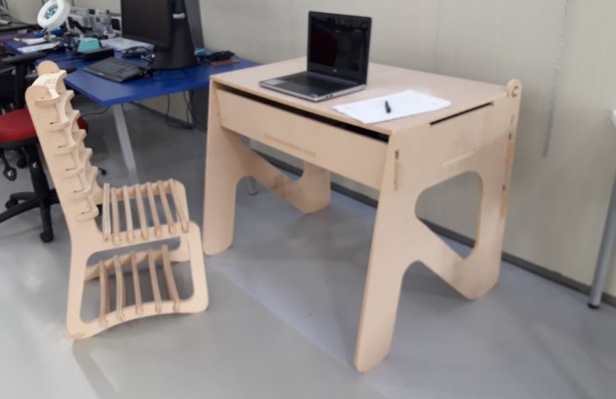
Then I started assembling the prototype
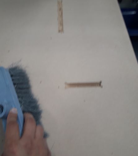
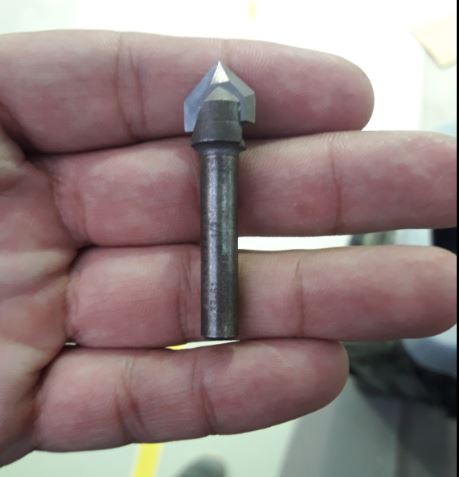
I will use this tip to grab description in the surface.
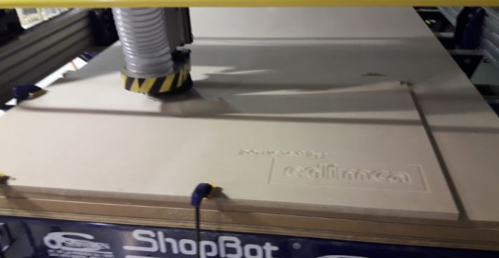
EDIMCA is an Ecuadorian company that comercialize wood, for this activity they have collaborated with a donation of MDF wood plates to make this activity
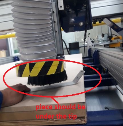
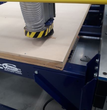
In the configuration we specify the thickness of the material in an exact way to be cut, what the head made is to leave a last layer that the tip was not able to cut, so I had to pull the piece out of the wooden board.
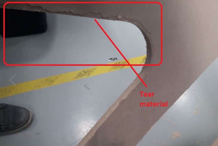
The solution to this problem is to set the depth of cut with one or two millimeters more, for the activity, after the cut I rale the sanding of the surfaces and the edges of the pieces.