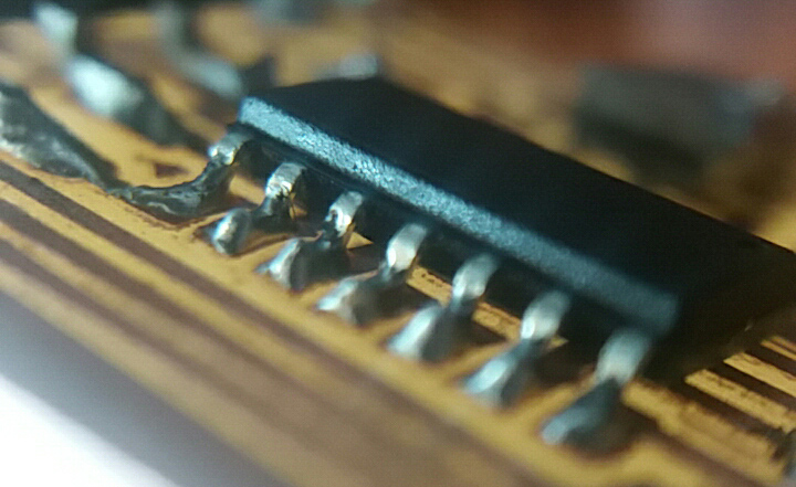
Programming (and reprogramming) microchips was a gamechanger at it's time. Here we are going to explore how it works and how to make it.
assignment
Documented what you learned from reading a microcontroller datasheet
The datasheet information contains important information about the performance and programming of the chip. Here we are going to make an overview.
The microcontroler datasheet we are going to read is the Atmel 8-bit AVR (R) family, that includes the Attiny 24A, Attiny 44A and the Attiny 84A chips. They are included in the same Datasheet, as they are closely related.
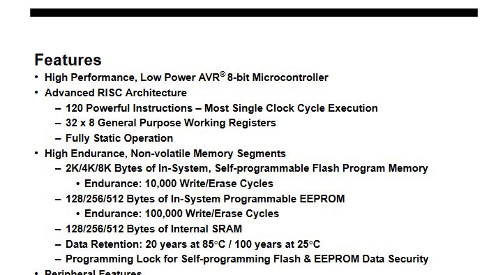
First, we find the features of the chip family. Here we can find information about the performance, arcitecture, features, voltage of operation, speed of operation at diferent cristal/resonators frecuency and voltages, temperature of operation and power consumption, among few others.
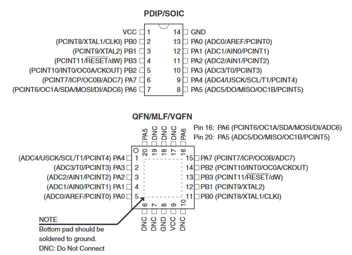
One of the key things found in a Datasheet is the pin configuration scheme. We can find the SMD and the block versions of the chips. This is an important reference to have at hand, in order to make our conections right and use the appropiate pins.
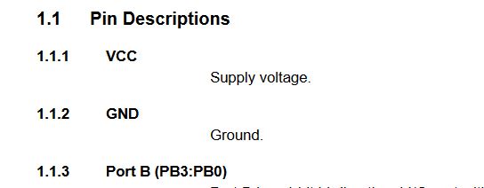
The next part describe the type of pins available for our pins. Basically we have Power (VCC and GND), Ports A and B explaining their differences and an explanation of the Reset pin.
Then, there is a description of the RISC architecture, chip's internals, interrupts, programs, resources, and more specs.
There are also instructions and explanations of the use of the fuses, and how to set the chip with external or internal resonators.
It is possible to use the internal comparator voltage for analog voltage meassurement, or use an external source, and change the sensitivity of the sensor used.
There is information about the 8-bit analog to digital converter, how it works, and how to use it.
The use of the PWM (Pulse Width Modulation) for the generation of a pseudo-analog signal is also described in the chip's datasheet.
An example of the logic used in programming you can see the example of the class Input devices.
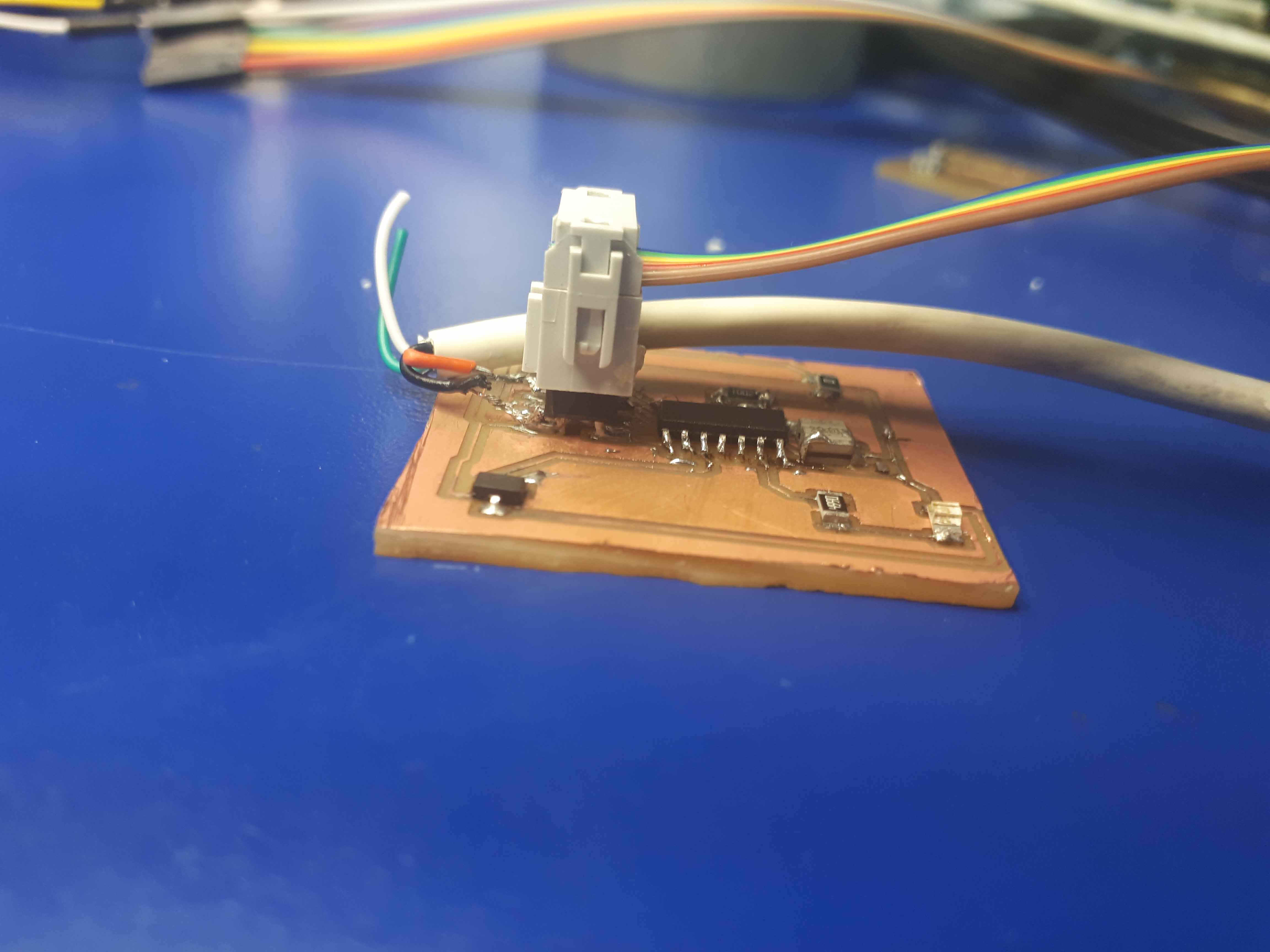
Here is the board (Attiny44A based chip) beeing programmed.
Other languages and other software:
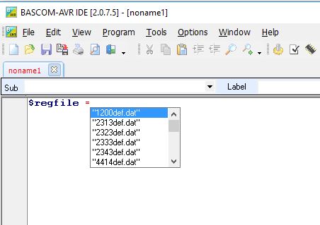
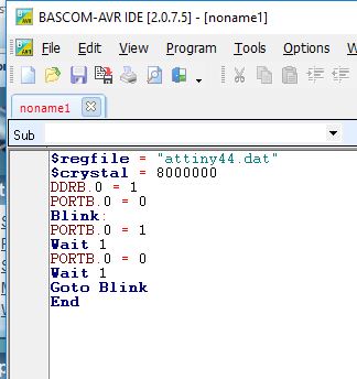
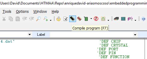
Experimenting with other software, I tested the program Bascom with the C language over an AVR microcontroller. First, we define the chip we are using with the code $regfile = "attiny44.dat"
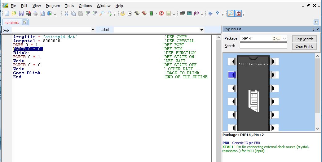
When we select the attiny44 chip, we can see it graphically. We also can see a description.
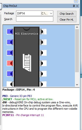
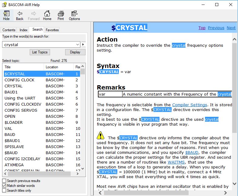
In the right part, we see more specs. Help ---> Index gives us the info, if we need it.
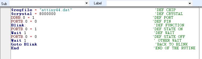
Then we continue with the programm. with $crystal we define the speed of the crystal we are using. DDRB.0 = 1 defines the port as an output (code 1). PORTB.0 = 0 defines the specific pin. We name the subrutine as "Blink" with a colon. Then we define the pin as a logic high, with = 1. Then we make a pause with Wait 1 (wait for a second), then we set the pin as low = 0 and wait for another second. Finally, we close the loop calling the function Goto Blink, and close the subrutine with an End command.
With the ' simbol we can add comments.
If we select the pin in the code, we can see it highlighted and with the description in the right part. It's very useful.
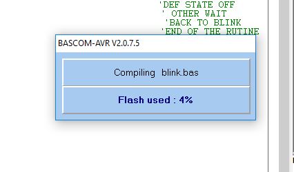
Then we can proceed to compile the programm clicking on the button or pressing F7.
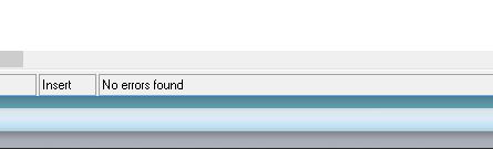
It compiles with no errors and tells us the memory used.
And no errors shown.
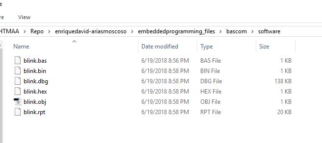
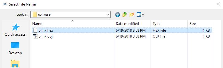
In the folder we saved the project we can find a few files. The blink.hex Is the programm we are going to use for the simulation.
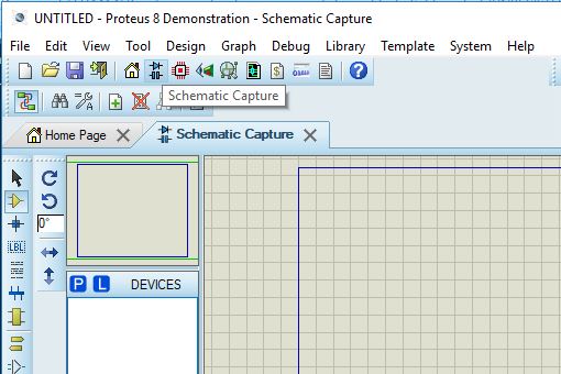
Then we open the program Proteus. There, we click on the Schematic capture.
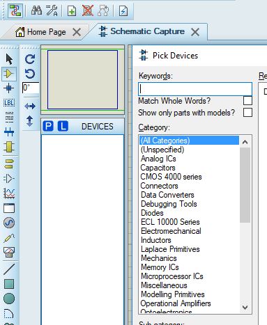
Then we click on the "P" button and in the search window under "Keywords" we choose our parts.
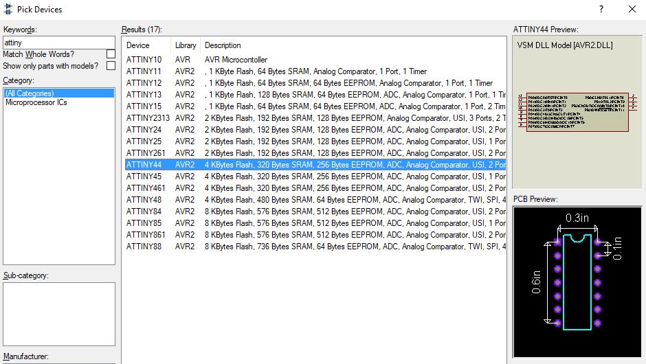
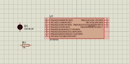
There, we choose our chip (Attiny44).
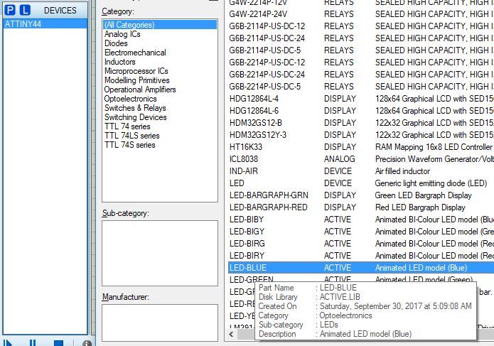
After we locate it in the stage, we choose the next component (a blue LED).
And a resistance. Here we can see all in the stage.
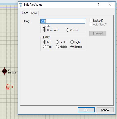
We can change the values of the components. Here we can see the resistor set to a value of 220 Ohms.
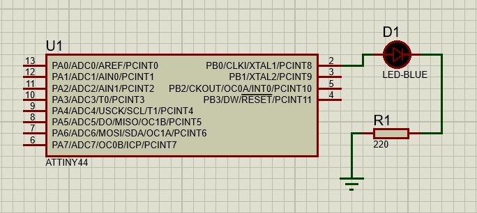
Then, we connect our components.
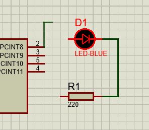
Here are all of them connected.
We double click in the chip, and we can see the configuration.
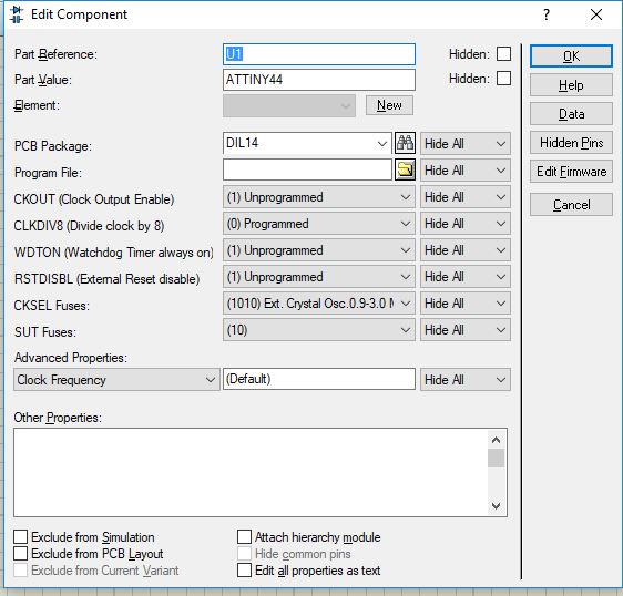
Here we click on the folder icon in the "Program File" line.
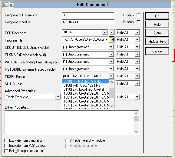
Then we tried the simulation. We had an error.
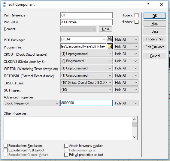
We found that our error was caused by not defining correctlly the Fuses. We fixed it...
And it finally worked!
Other architectures:
For this part I used the programm Flowcode, that can be downloaded following the previous link.
This programm is very intuitive, and have a graphical intefase eye-candy-like, that somehow resembles Skratch.
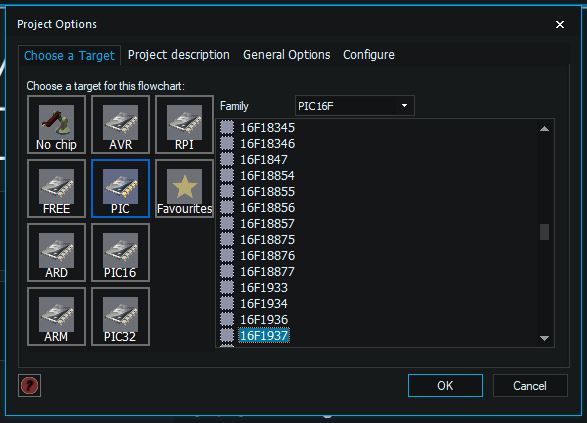
In this programm, first we open a new project and choose the chip we intend to programm. In this case, the Pic 16F1937.
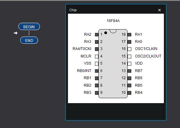
Once choosen, we can see a graphical representation of the chip, with the pins and pin names. We also see the bare minimal, graphical structure of the programm, that includes only the Begin and End. We also see an arrow that indicates the place where we can insert new code.
We can also include the components we want in our circuit. In this case, a LED array conected in PORTB.
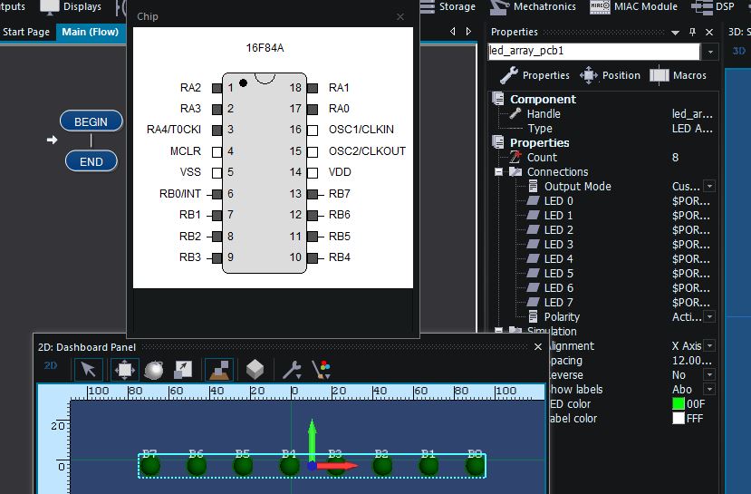
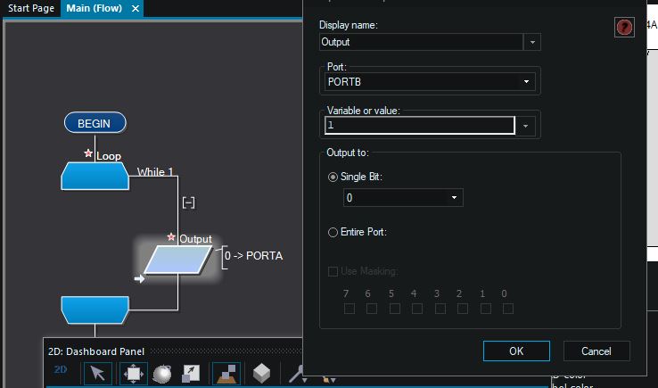
For recreating the Blink program, we insert a loop between the Begin and the End, and inside it we insert an output. We can edit this output, cahnging the name, the port, or select the entire port, or a sigle bit in the corresponding array number. In this case, the value 1 (LED HIGH, of On),
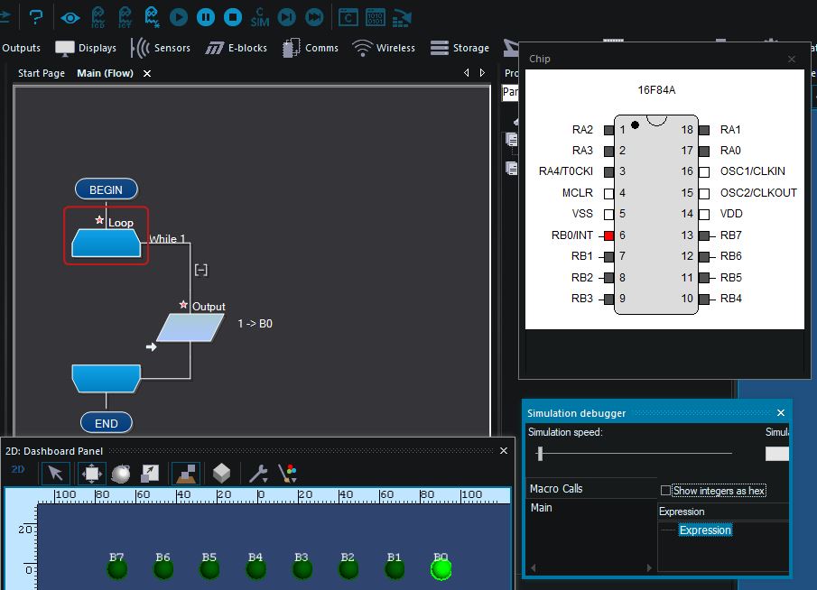
In this case, we can see that the LED in B0 lights up in the simulation.
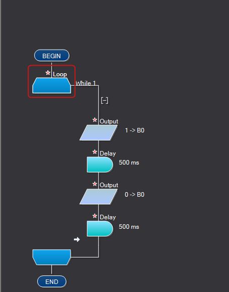
We continue with the programming, adding a delay of 500 miliseconds before the same PIN/LED repeats it's appeareance, but in this case with the value 0 (off). After this happens, the loop starts again.
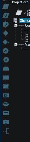
In the left pannel we can see the tools we can use for the programm design. Some of them are self-evident, as they follow flux-diagram conventions. Some of them still unknown for me, but i guess is part of the learning curve, and in the future, if I continue using this programm, I will understand it better and use it.
Finally, we run the simulation. Here we can see the LED choosen, blinking.
The datasheet of the chip pic 16f84a is in the public domain, and can be found in the previous link with its name.
Clasic Aruino Blink
After the board was completed, a test program was uploaded (blink). It dindn't work at the beginning, but after providing power it did burn the bootloader and the sketches. Then I tested other programs, like make the LED light up with the press of the button, make the LED off if the button is pressed, and so.
Some sketches where uploaded. How they funcion is shown here:
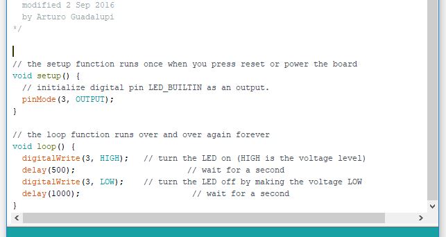
First, we are going to see the clasic "blink" sketch:
In this sketch, the void setup() routine, that runs once at the beggining of the programm (when the chip starts or resets) just define the pin 3 as an OUTPUT, via the pinmode() function. This function have two arguments, de first defines the pin, and the second sets it as an INPUT or an OUTPUT.
In the loop() part of the program (that loops forever... or until the chip looses power or integrity), the pin 3 goes to logic HIGH using the digitalWrite()function. Then, it waits for 500 miliseconds (half a second), and then writes a logical LOW (aka... turns off) and remains the same for a delay of half a second. Then, it repeats the first digitalWrite(). The number of the pins and the duration of the delays are changed from the original programm, to match the pin numbers of the arduino code/specific chip.
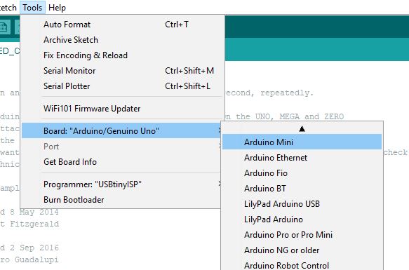
In the Arduino IDE we have to check that the board, the port and the programmer match our settings. If we are using a programmer, a shortcut is to press the shift key simultaneuslly to the programm load arrow.
The files used in this page can be downloaded from the following links:
Blink series used in the simulation:
blink.obj, blueLED.DSN, blink.rpt, blink.hex, blink.dbg, blink.BM, blink.bin, blink.bas, FlowcodeBlink.fcfx.
Arduino blink not included (public domain).
Blink original LED in pin 3, Blink modified to function using pin 3.
Blink Modified. Blink with a delay time reduced in the off mode, used for testing scripts.
Config 1 LED and button. LED On. If button in pressed, it turns Off.
Config 2 LED and button. LED Off. If button in pressed, it turns On.
