In this assigment we are going to experiment with the input captabilities of the microcontrollers. We are going to use the tiny but powerful Attiny44A.
assignment
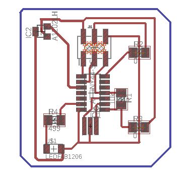
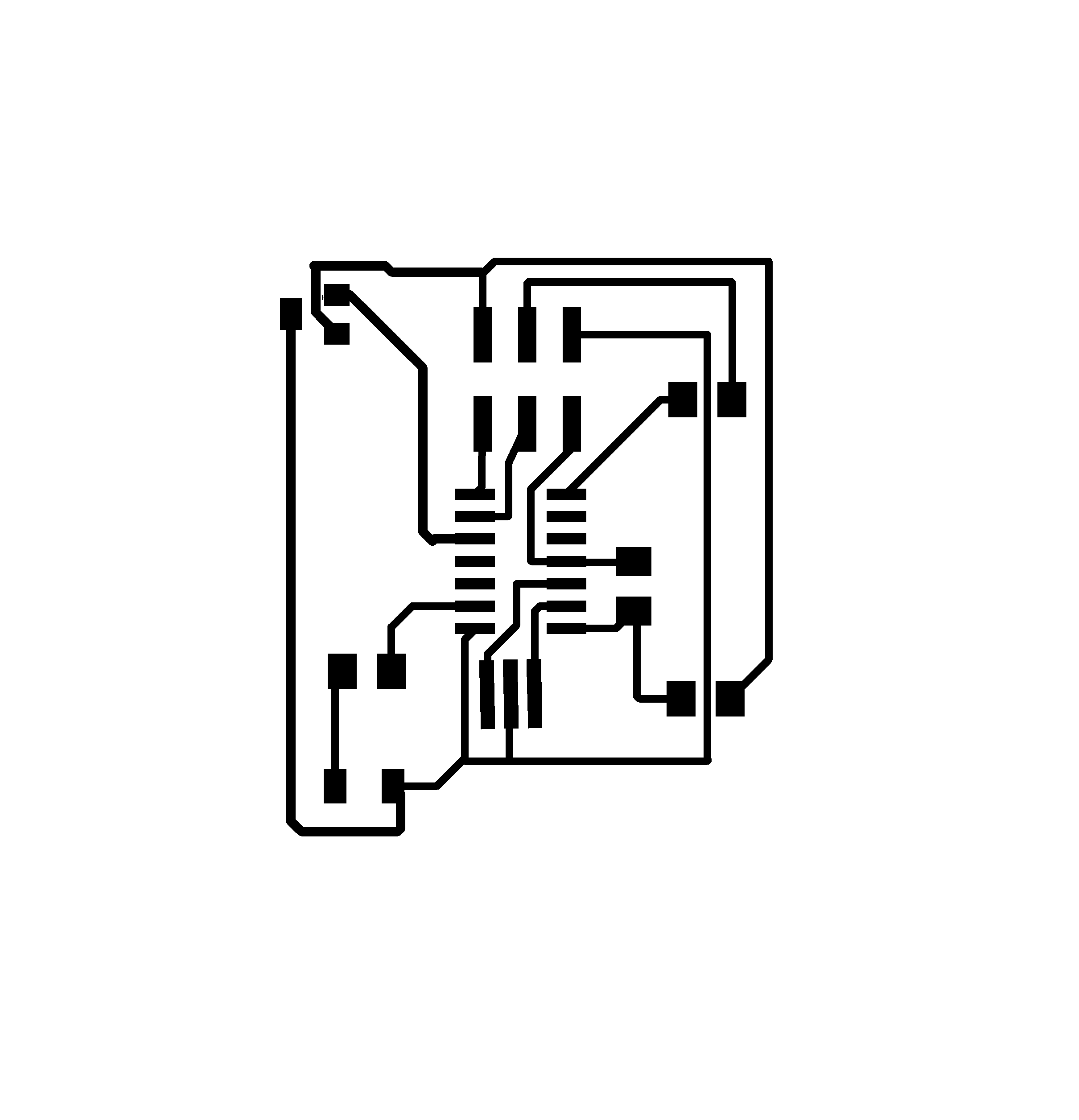
After the eagle design, we milled the traces using this file:

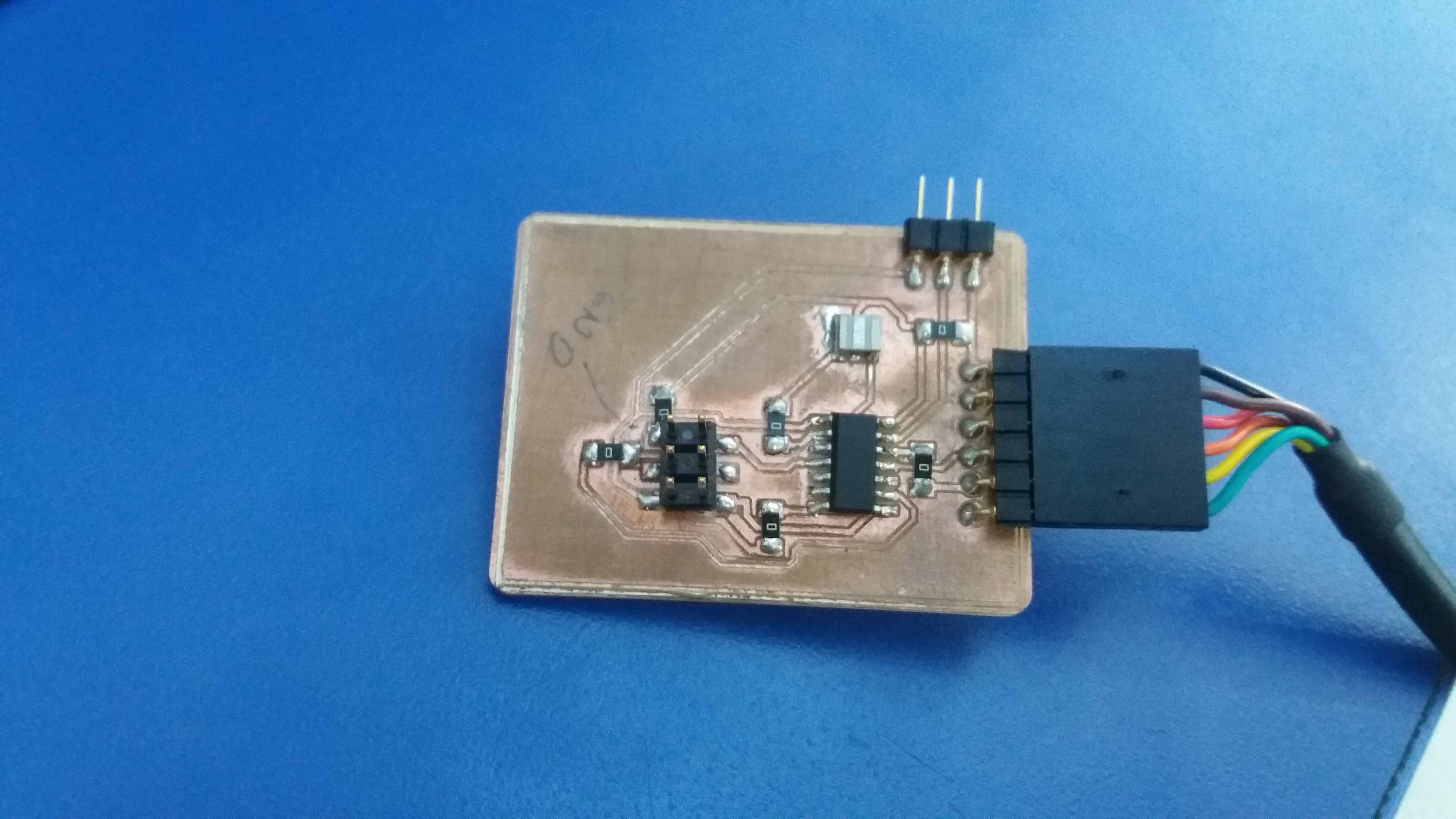
Here is the board milled and put together, with a ftdi connector.
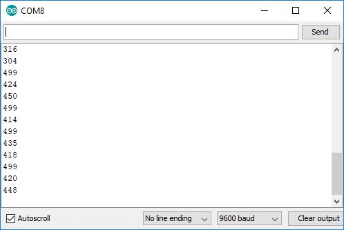
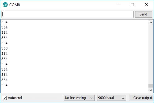
If we connect the chip to the computer, and open the serial monitor in the Arduino IDE, we see random numbers between 300/450. I guess it's picking up ambient noise.
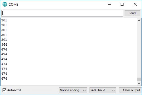
But if we connect a potentiometer in the input (ground, vcc and signal)...
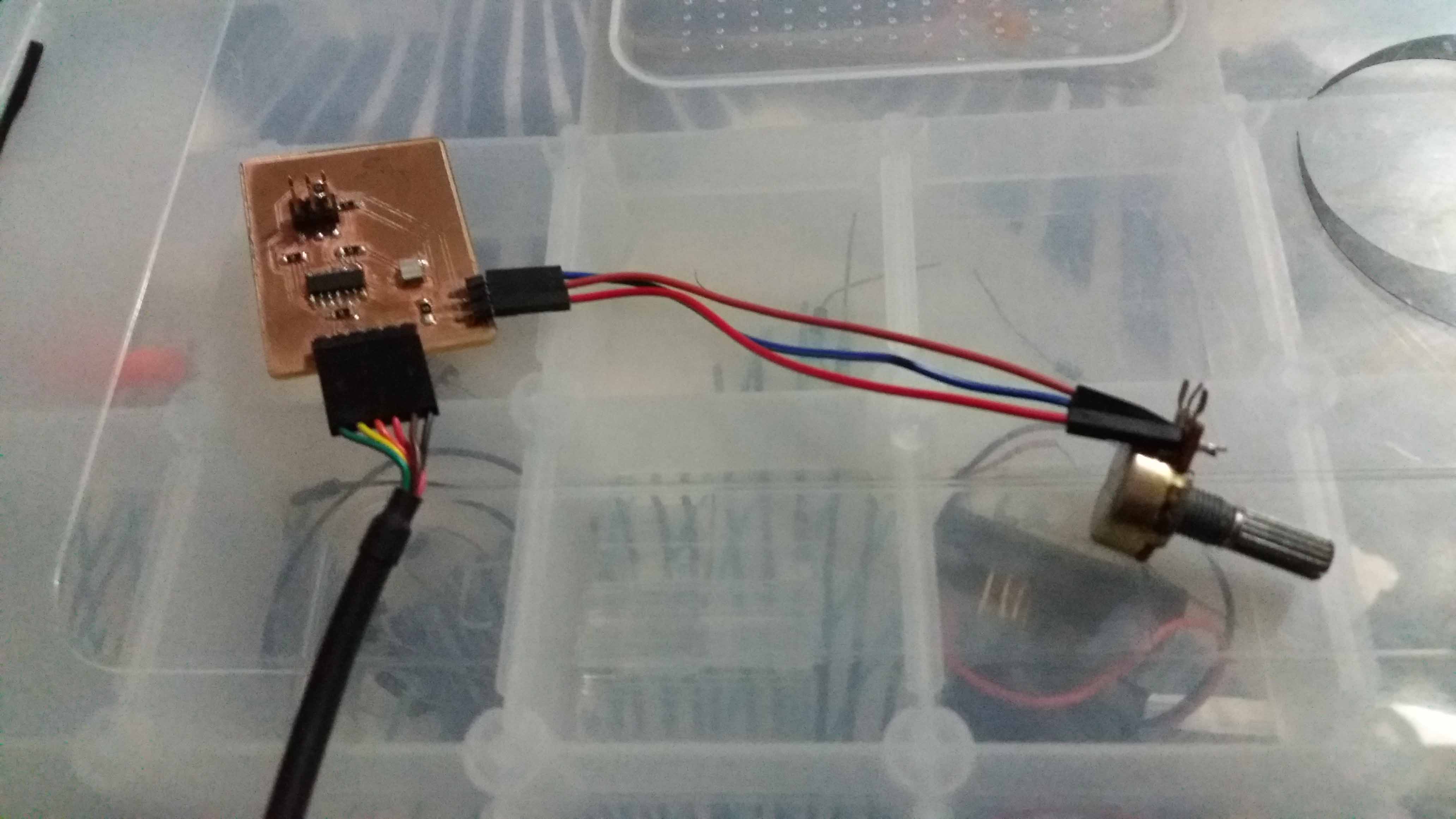
We see that the signal stabilizes.
If we move the potentiometer knob, we se that the values change very precisely. If we let it go, the signal remains stable.
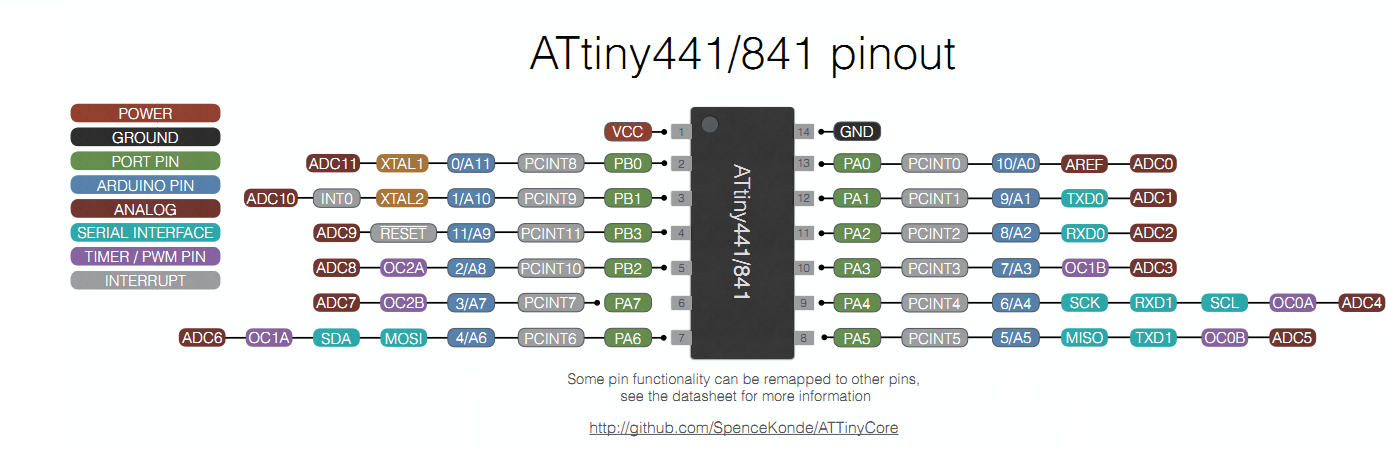
For programming, this table might be very useful in order to find the correspondance between Arduino and Attiny44/84 pinout.
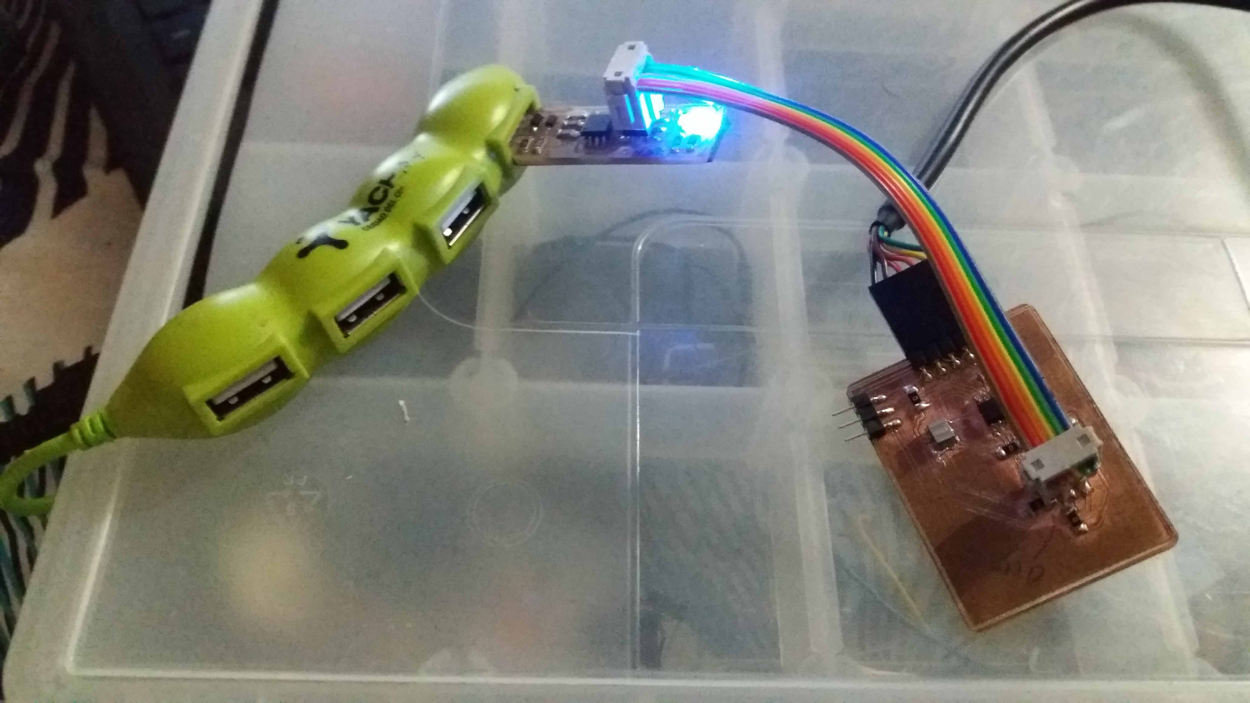
Here is the board beeing programmed.
We can replace the potentiometer for another kind of input. We just need to adjust the data processing in the code.
Hall effect sensor
I made another board, this time using an Hall Effect sensor. This device measure the change on electric current produced by a magnetic field.
So, for the design, I recycled a previous design (LED & Button board), and (LED & Button board), deleting the button with it's pull-up resistor and adding the Hall Effect Sensor.
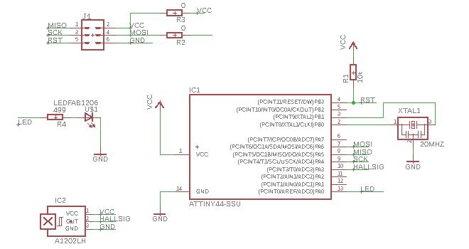
And using a layout that I like, specially the resonator configuration. I located the sensor away from other components, in the upper left corner, to avoid interference.
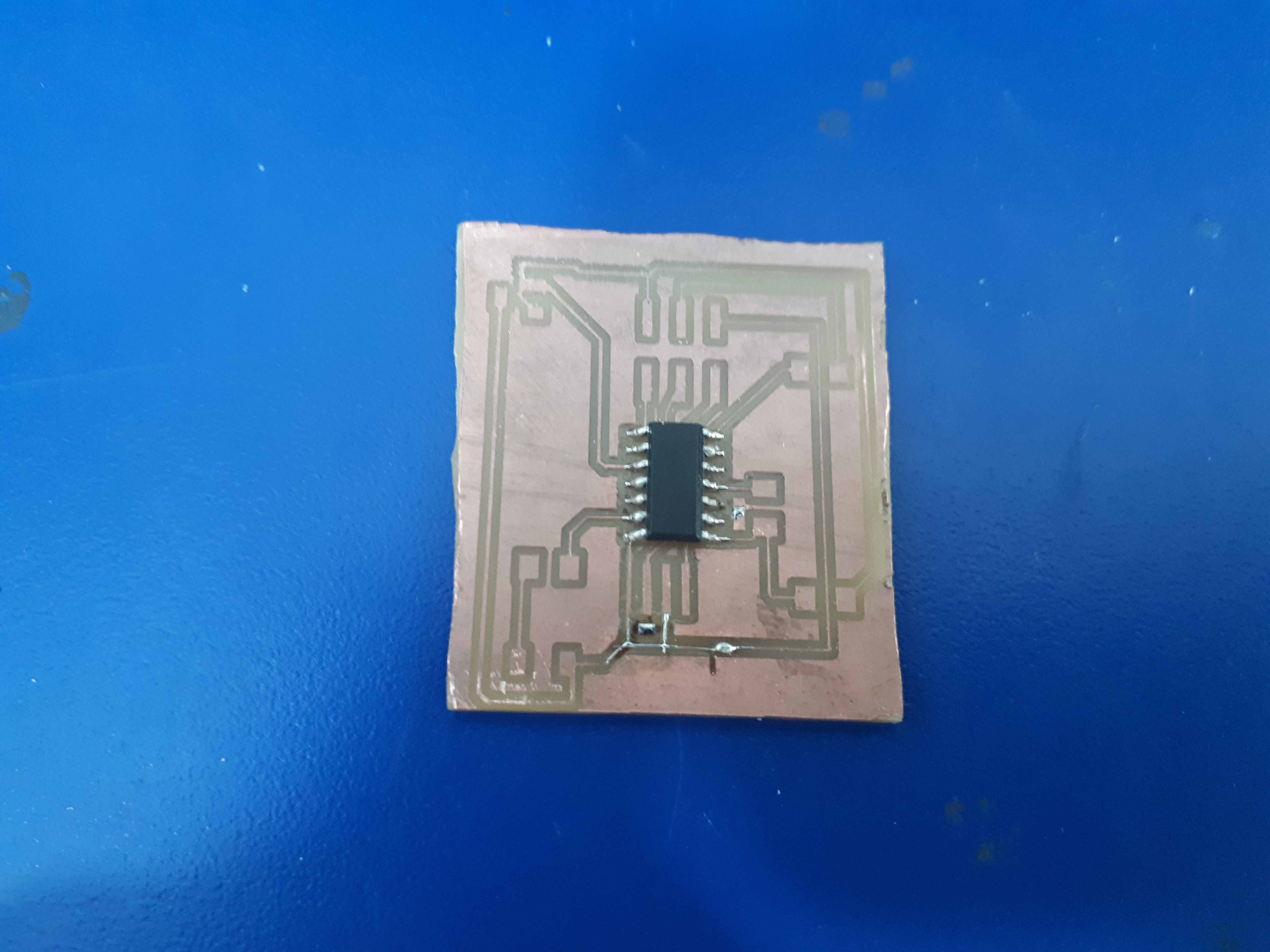
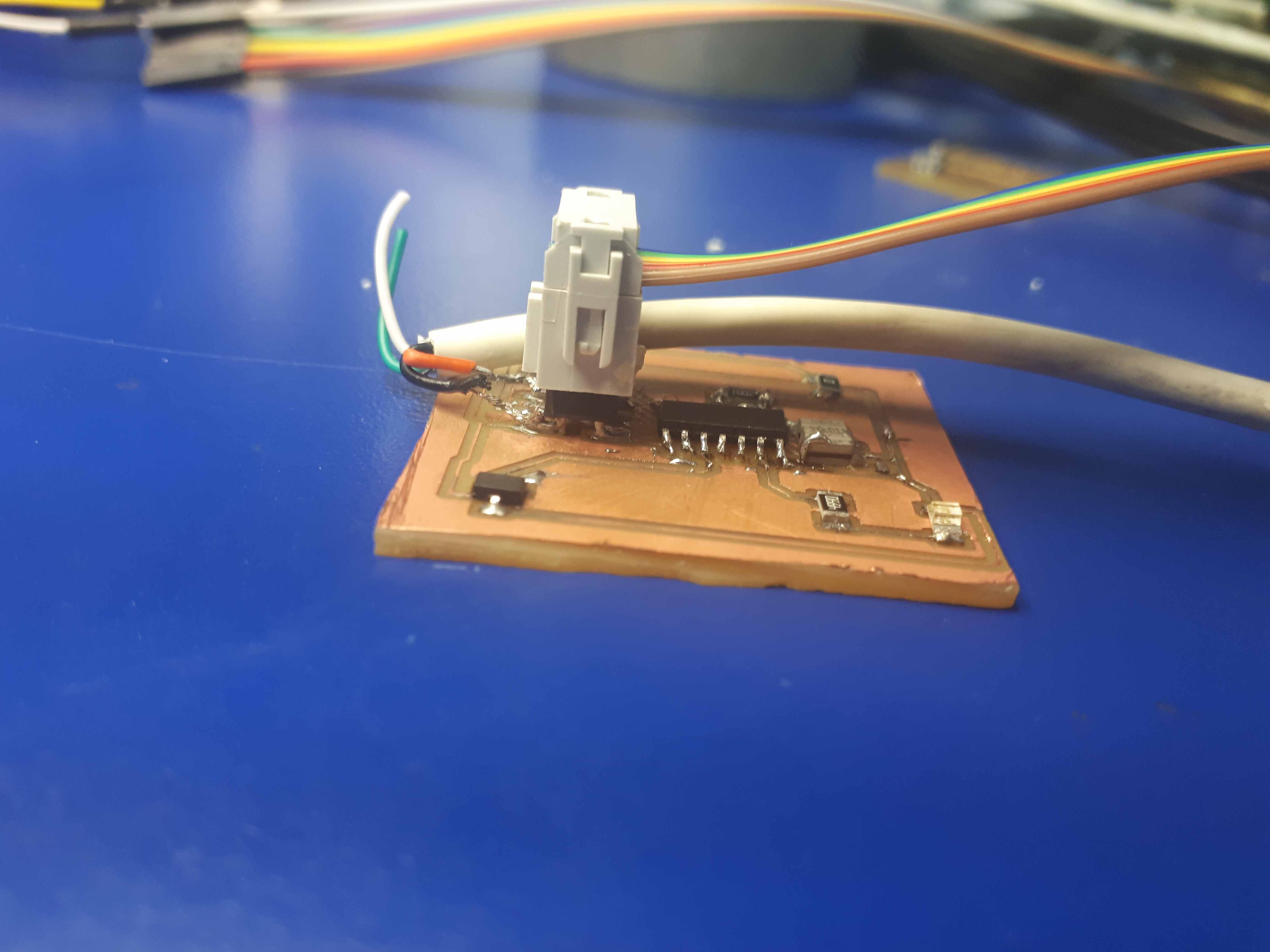
Then I proceeded to mill the board. Here is, milled and with the Attiny44 chip and some fixings. Sorry for the borders, I had to cut them manually.
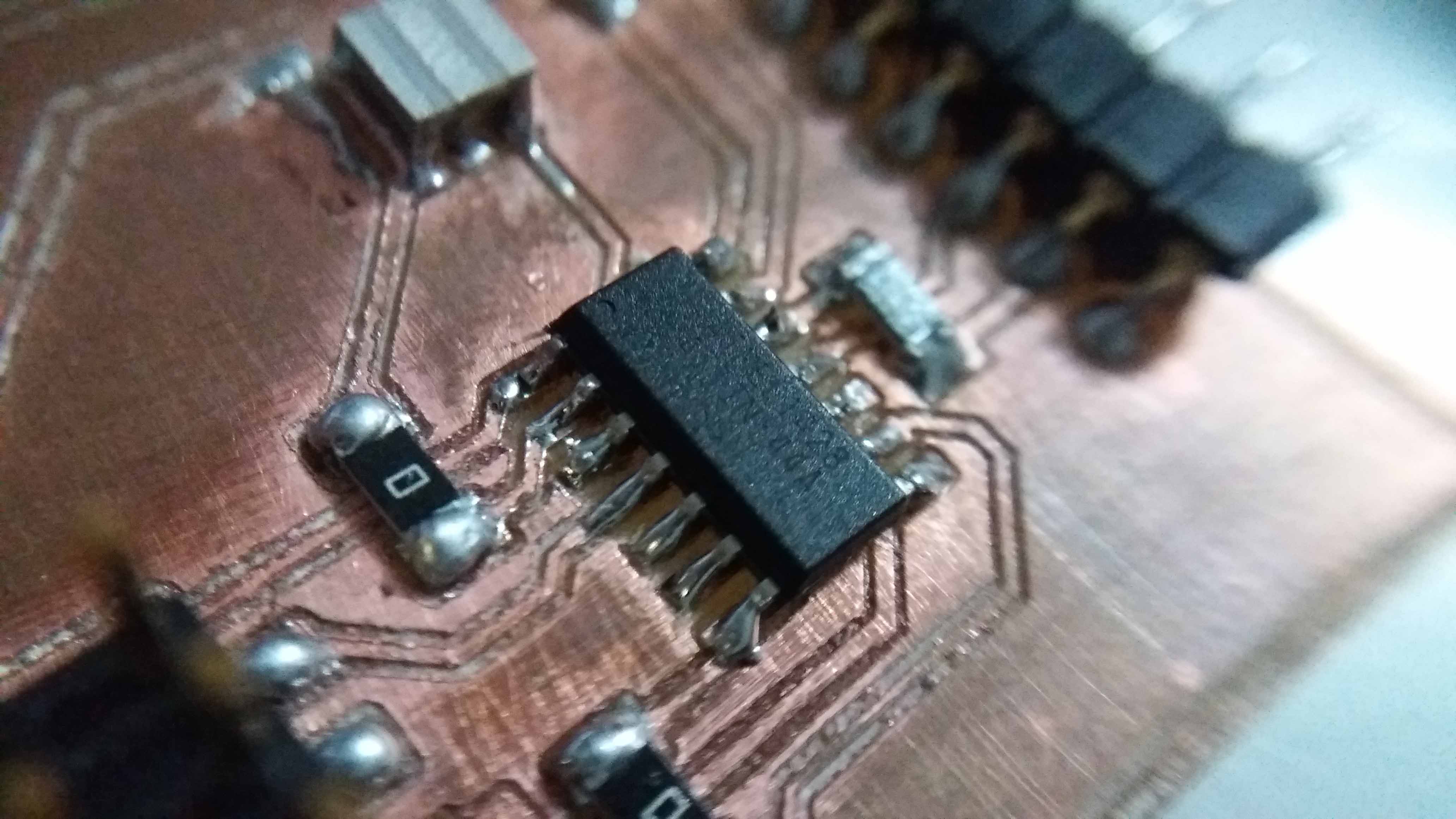
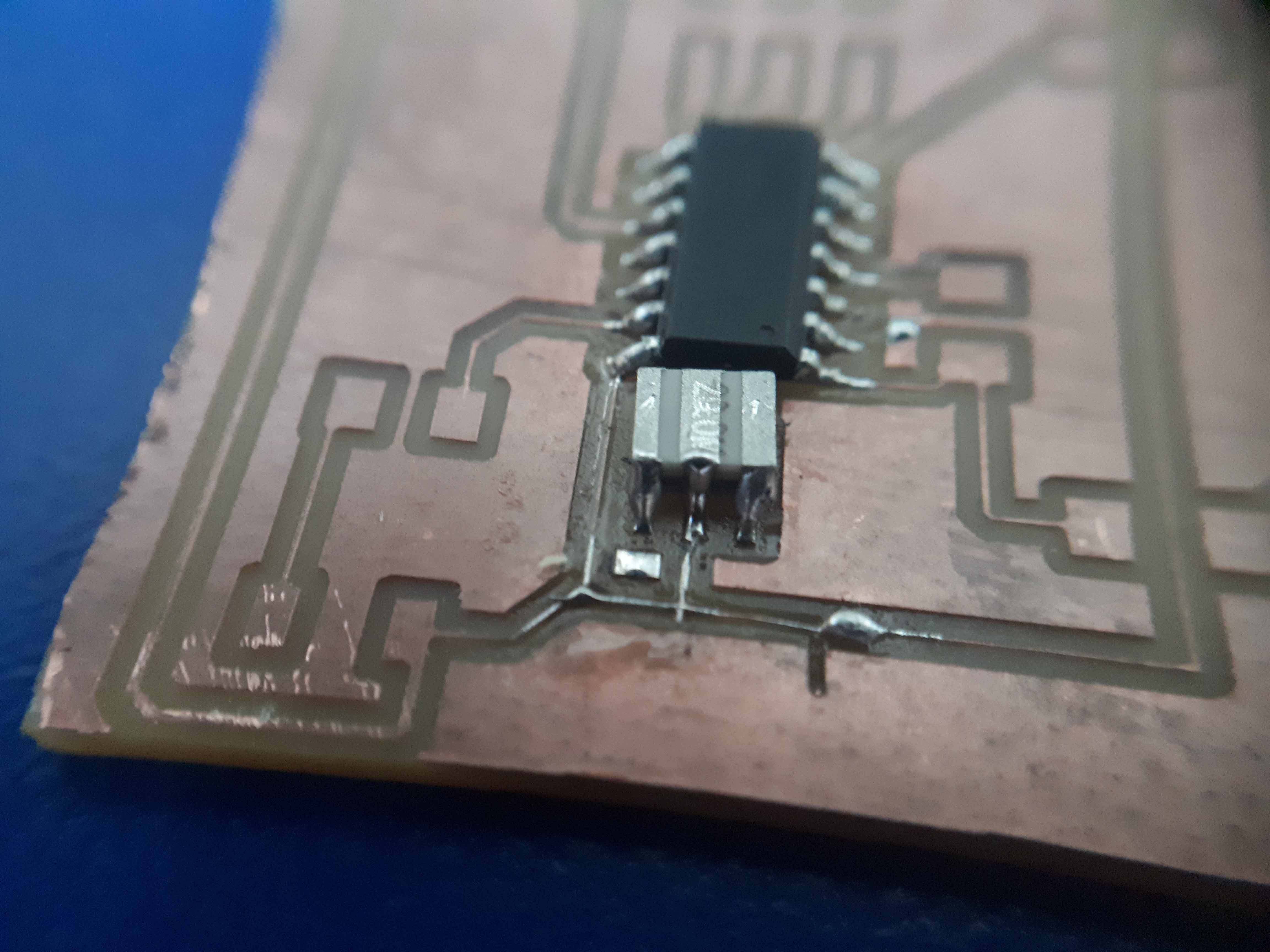
Here we can see the pads for the resonator, pre-tinned.
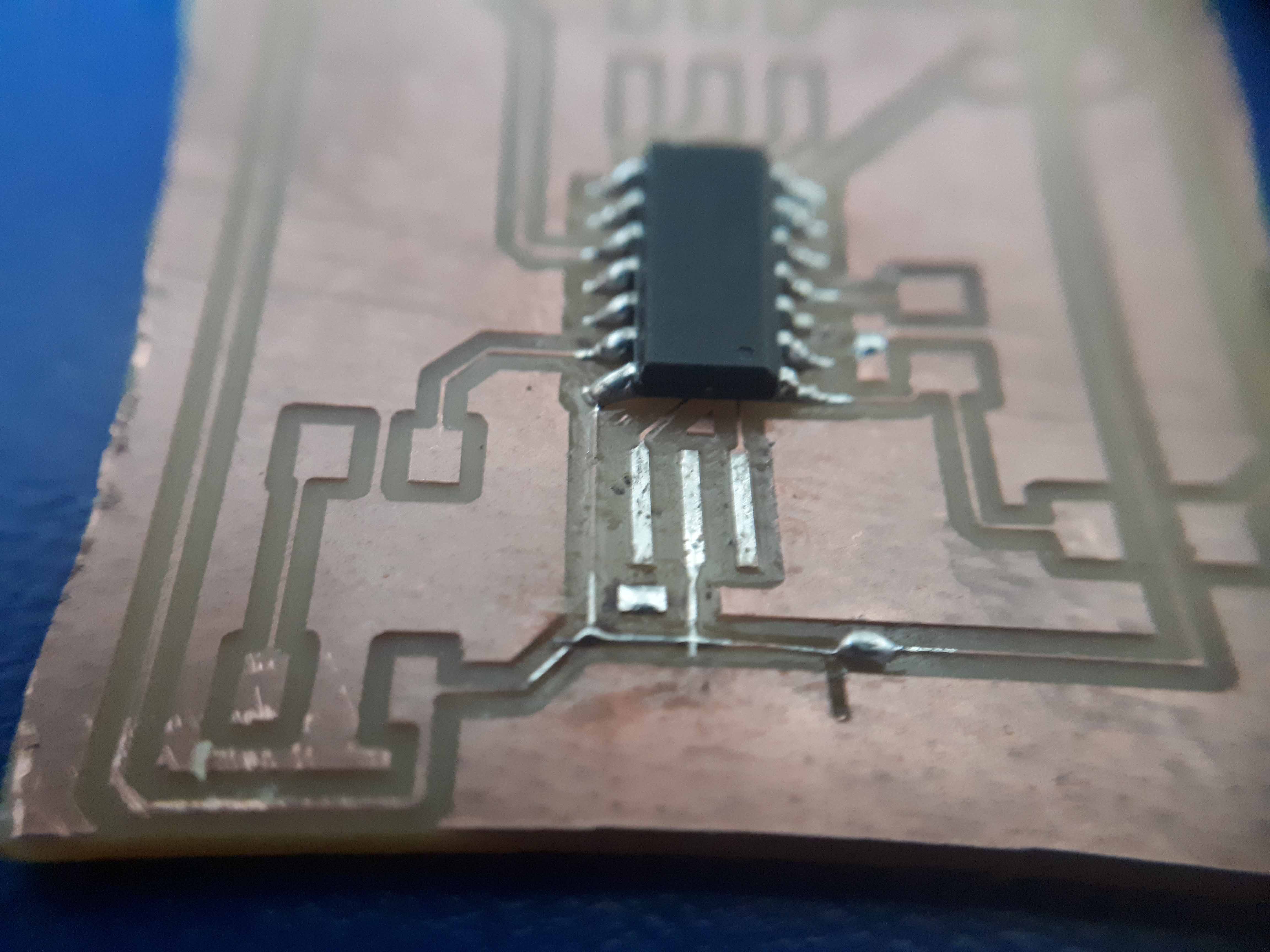
And here the resonator, in place.
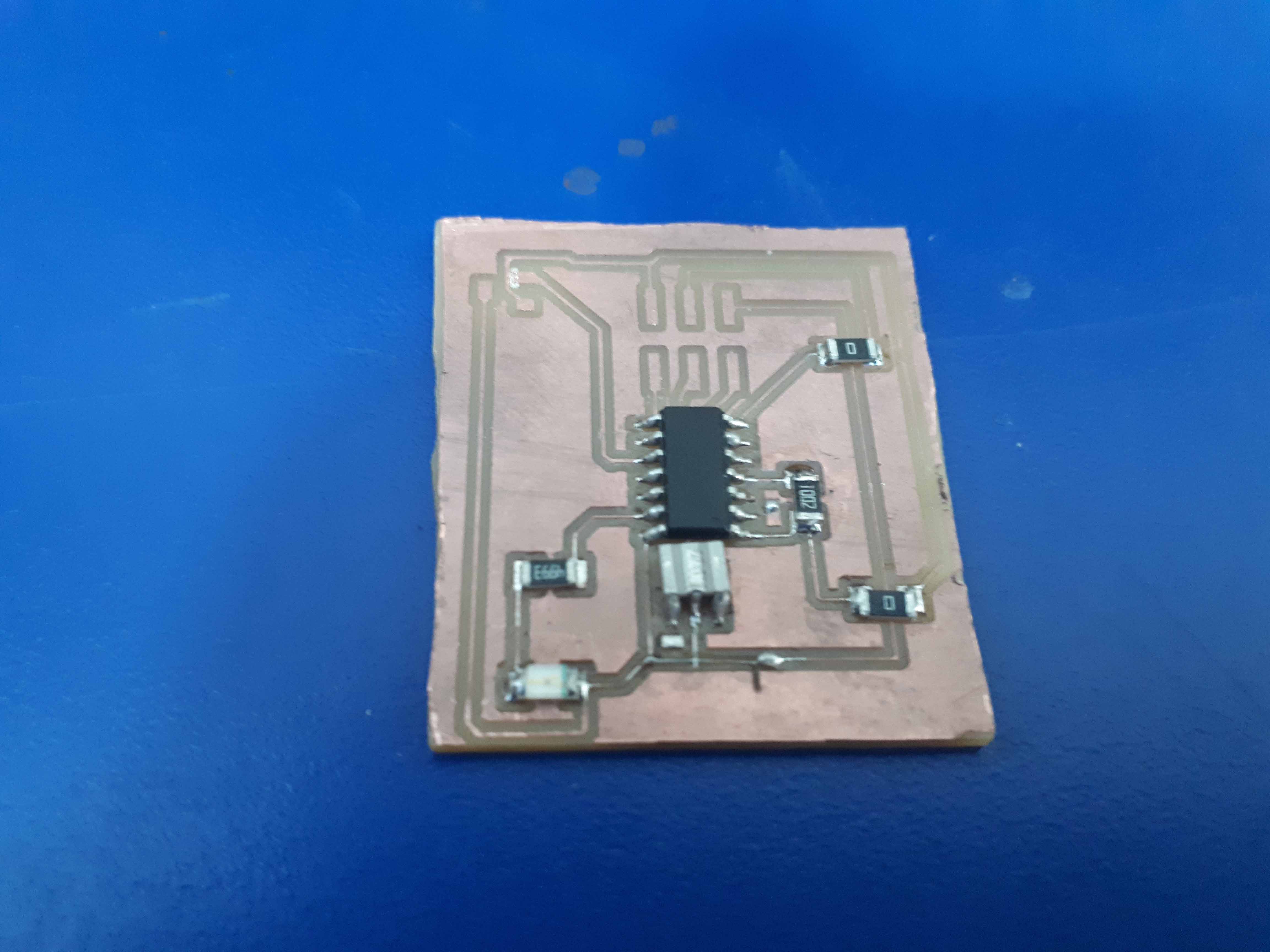
Here it is, with the LED and some resistors added.
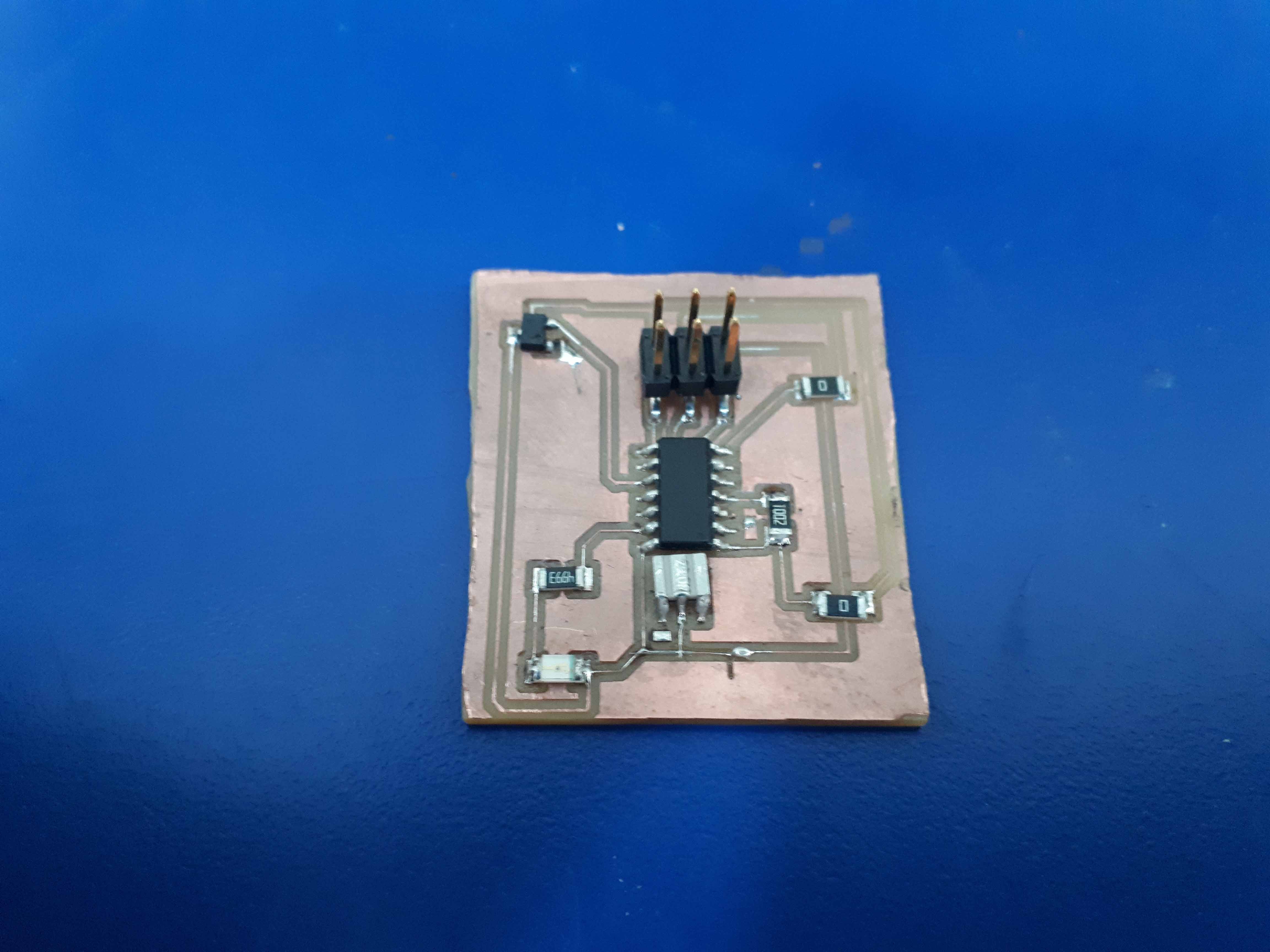
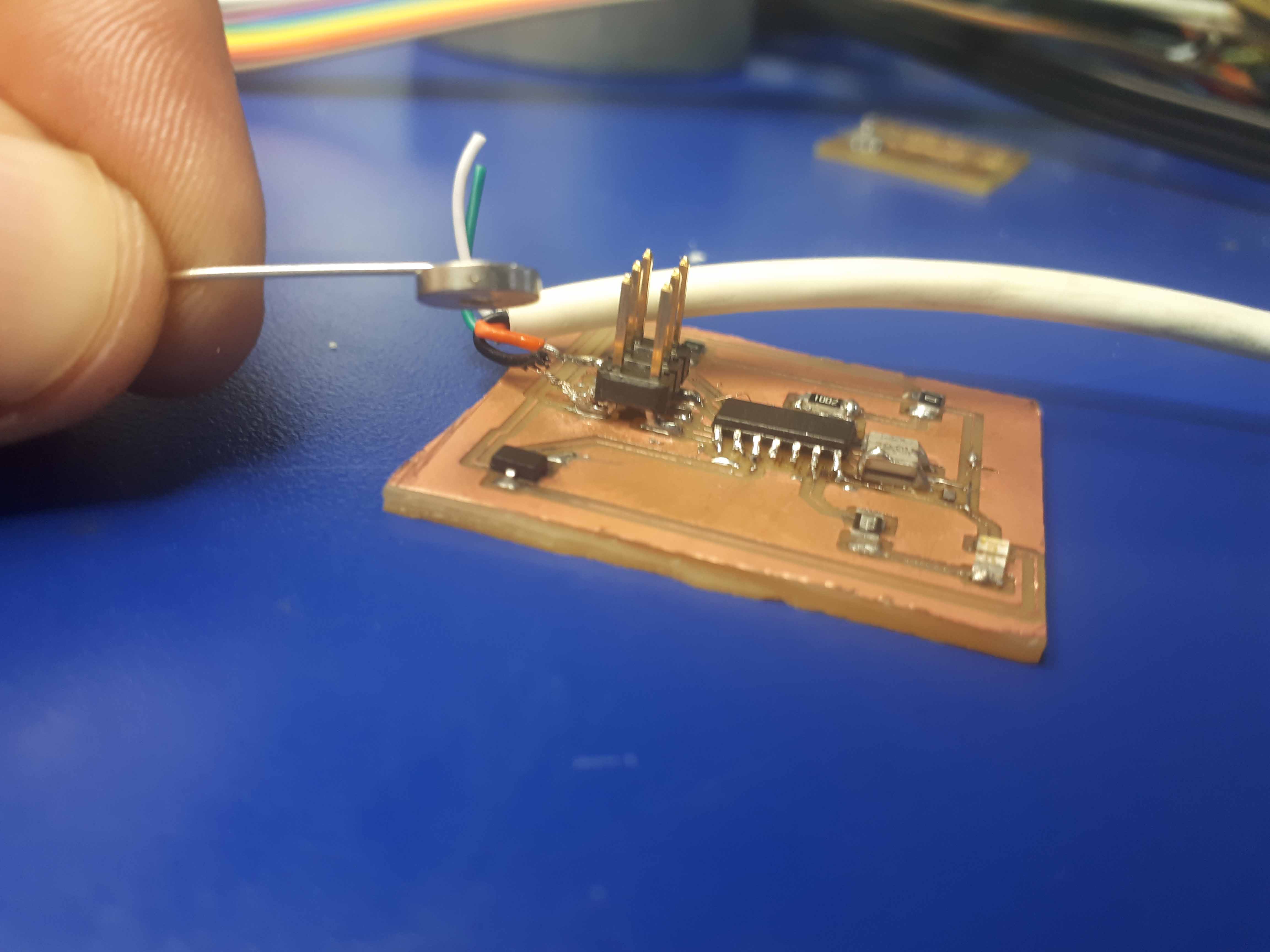
And here with the sensor and the programming header.
So, here is the code.
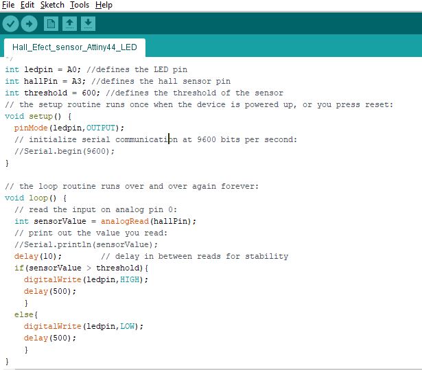
The code is commented, but I am going to explain a litle further. First, we declare a global integer variable called ledpin and assign it a value fo A1, that's the number of our Arduino correspondent LED output pin. We do the same for the input. We give it a name hallPin, and assign it a value of A3. I also created an integer type variable for the threshold of the value recroded by the sensor that will trigger my LED. It's useful to have it here, change it here if necessary, and reflect the changes in all my code.
Then, in the setup() function, we declare our ledpin as an output. We don't need to to declare the Hall Sensor as an input, as all the pins are inputs by default.
Once the setup is done (After powering the device), the programm will run the loop() function continously. Here, we start declaring a local integer type variable, sensorValue, and assign it the readings of the funcion analogRead(), with the argument hallPin (the pin we are reading from). The function analogRead digitalizes the analog signal resulted from the sensor voltage comparator, and converts it to a range between 0 and 1023, due to the 10 bits analog to digital converter.
After a delay() of 10 miliseconds of argument, for stability, we present two conditional states, one in which the value red by analogRead() and assigned to sensorValue is greater, than the threshold, (in this case 600, determined experimentally), it will do something described in the brackets that follows the conditional (if(){}, in this case). Otherwise, it will jump to the else part of the conditional, and execute the code described inside its brackets. In this case, if the first part is true, we will light the LED with the function digitalWrite() with the first argument as the name of the pin you want to use, and the digital/binary state (HIGH or LOW. HIGH, in this case). In the case that a magnetic field lower than threshold 600, the function will be the same, but this time we set the second argument to LOW (tur off the LED). In both cases, we use a delay of half a second.
Well... after disecting the code, we compile it and load it to our device.
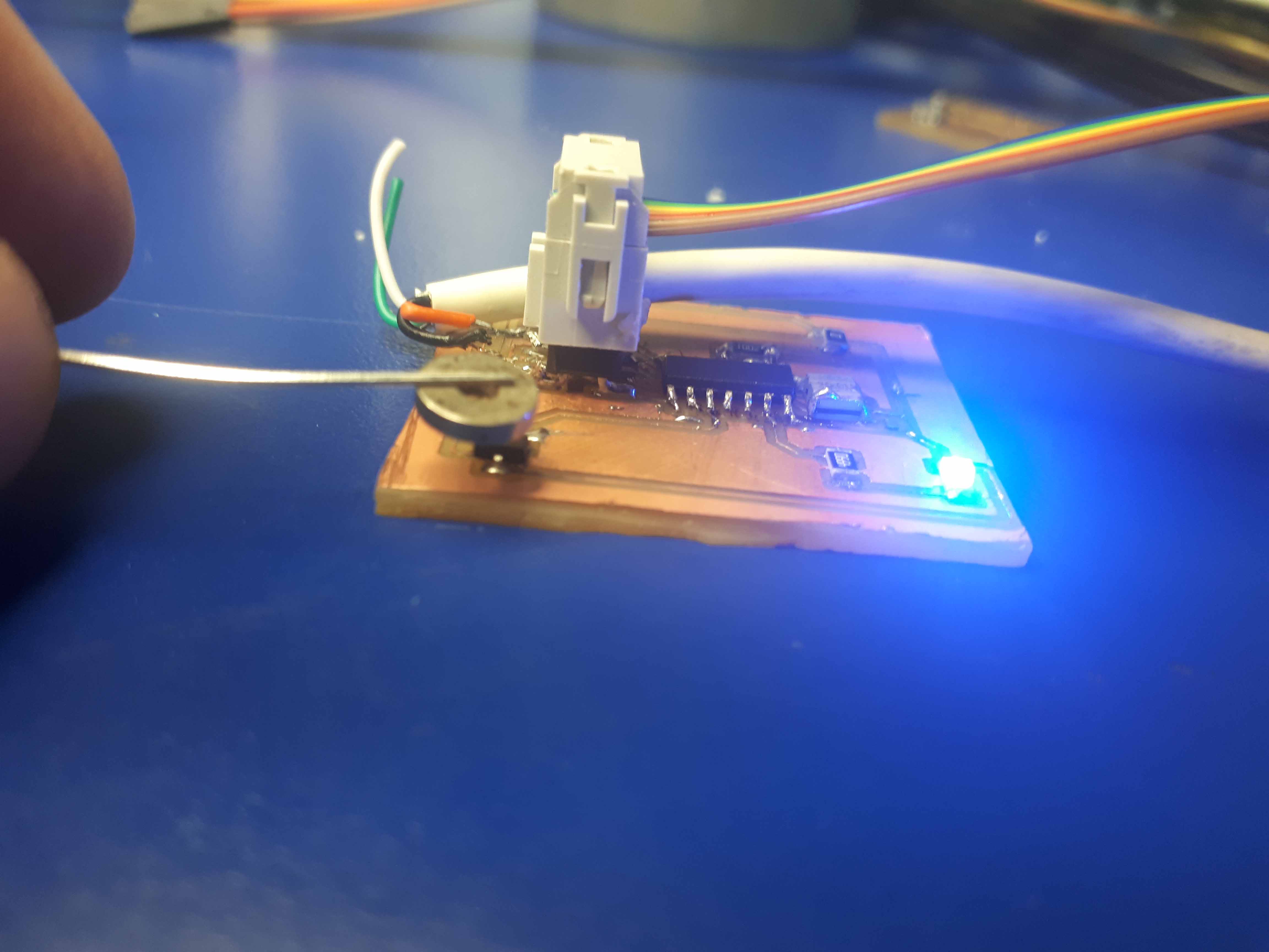
Then we make close a circular magnet to the Hall Sensor.
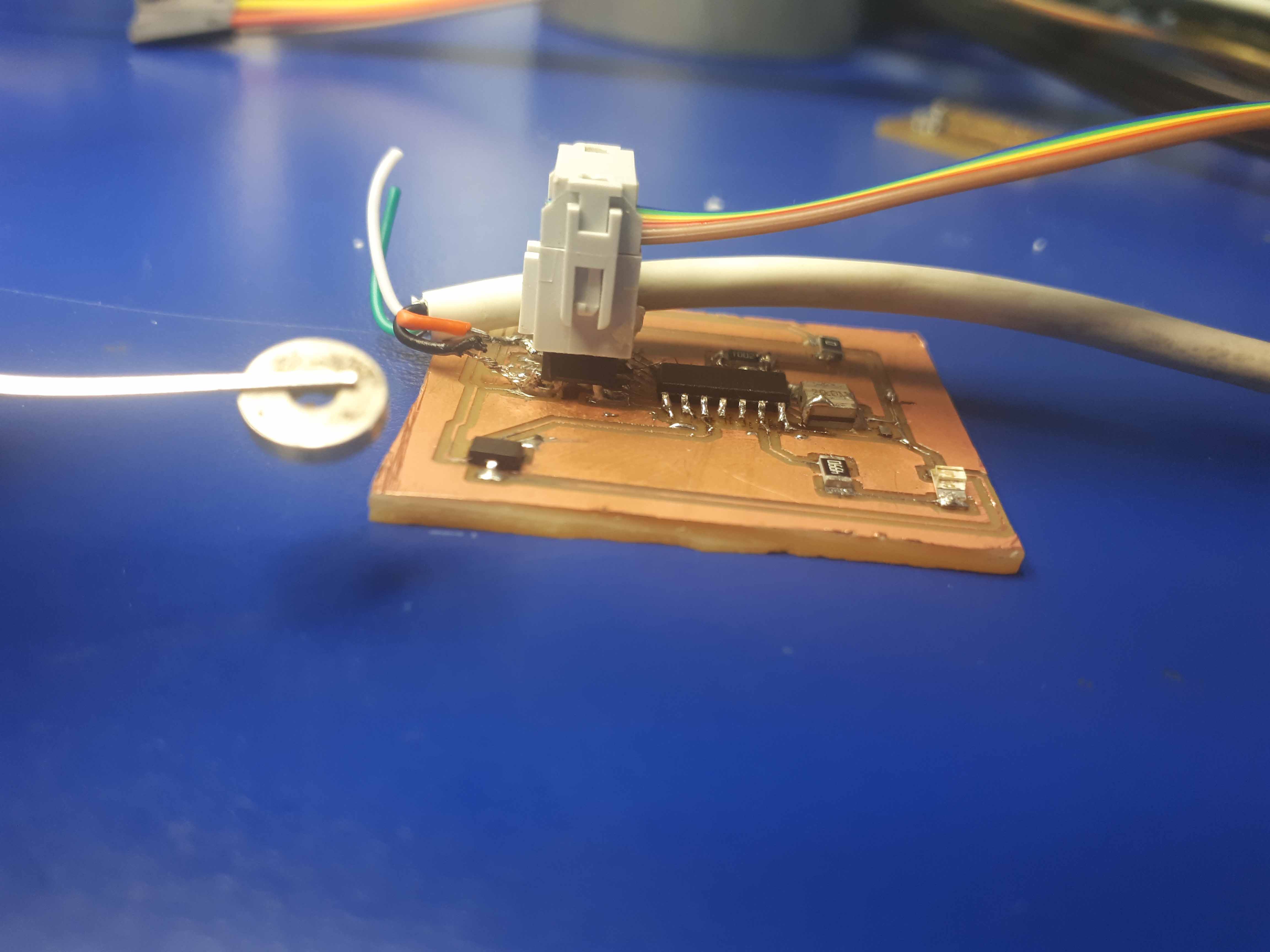
And see how the LED lights up!
Then we disconect the programmer, and test it stand alone, with just 5V.
Here is a little video of the device in operation.
Here are the files to download: Cut png, Cut rml, Raster1 png, Raster1 rml, Border png, Border rml, Sketch for input, Hall-schematics, Hall-board, Hall-code, Hall-traces, Hall-border.
