With the current fabrication technology, we can fabricate and program our own boards. This will be an overview of what we made.
Learning outcomes:
- Describe the process of milling, stuffing, de-bugging and programming
- Demonstrate correct workflows and identify areas for improvement if required
assignment
Shown how you made and programmed the board, explained any problems and how you fixed them, included a ‘hero shot’ of your board:
First part: Hardware.
The first thing we have to do is feed our bit-atoms interface (our CNC machine) with the right kind of data.
I am going to use the FabISP programmer model. Here are the instructions.
It is important that at this point in the design, a png document with a high resolution (1000 dpi).

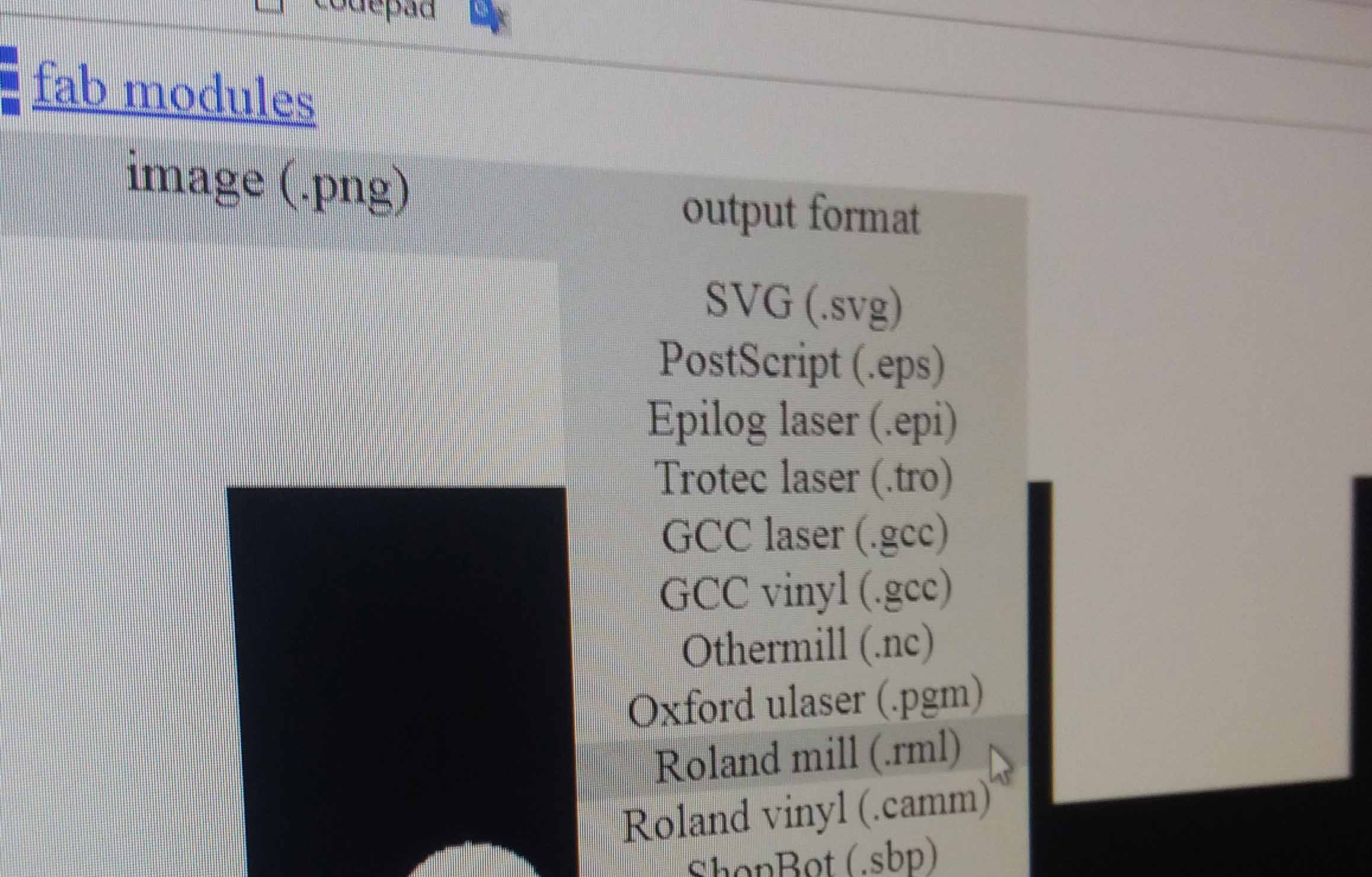
This will be our traces. We set the machine with a 1/64" bit. We use the resource Fabmodules. There, it is possible to upload the PNG document, and choose our machine and other parameters. In this case, the machine Rolland mill (.rml) was used.
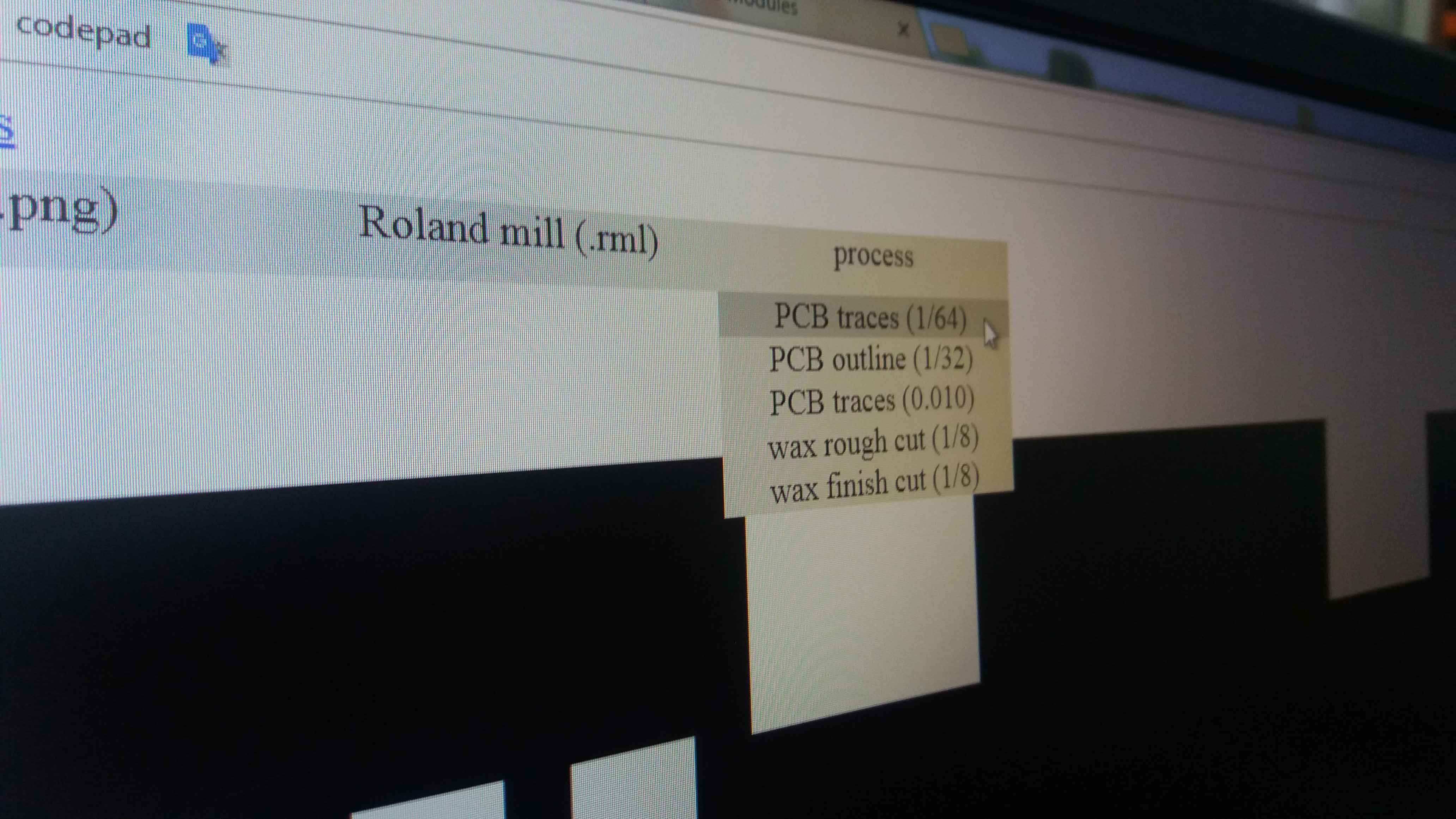
Then, in processes we choose our kind of work. For the lines, we choose PCB traces (1/64).
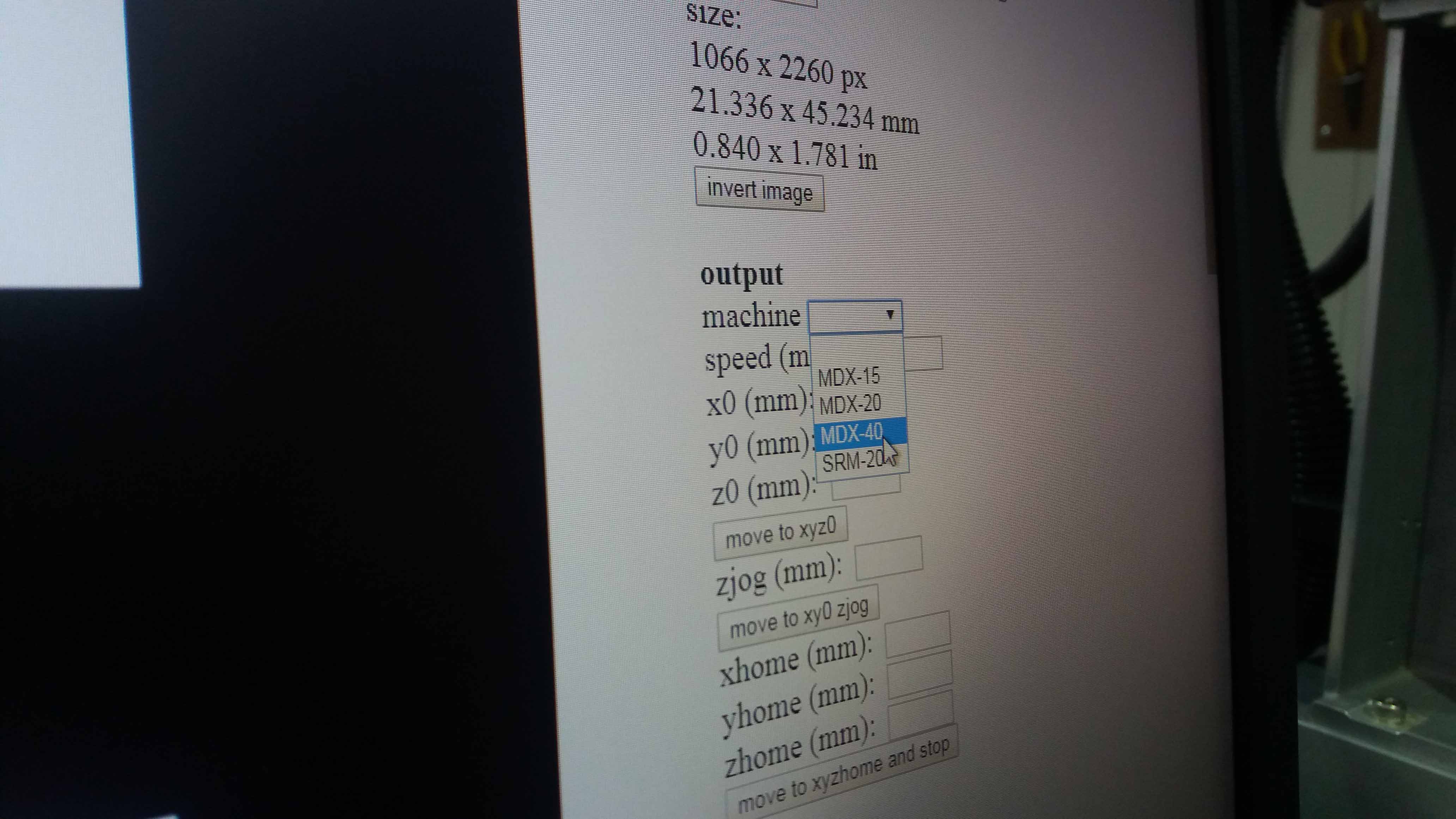
And then, the model of our machine. Fabmods is going to calculate the path.
Make the necessary changes if needed, save the file and open it in the computer that controls the machine.
For particular changes in the machine's setting, we refer to the test also explored in electonics design assigment. Here is a picture of the test:
The expanation of the test is shown here.
Machine settings
The setting can be made via software and hardware. We tried both.
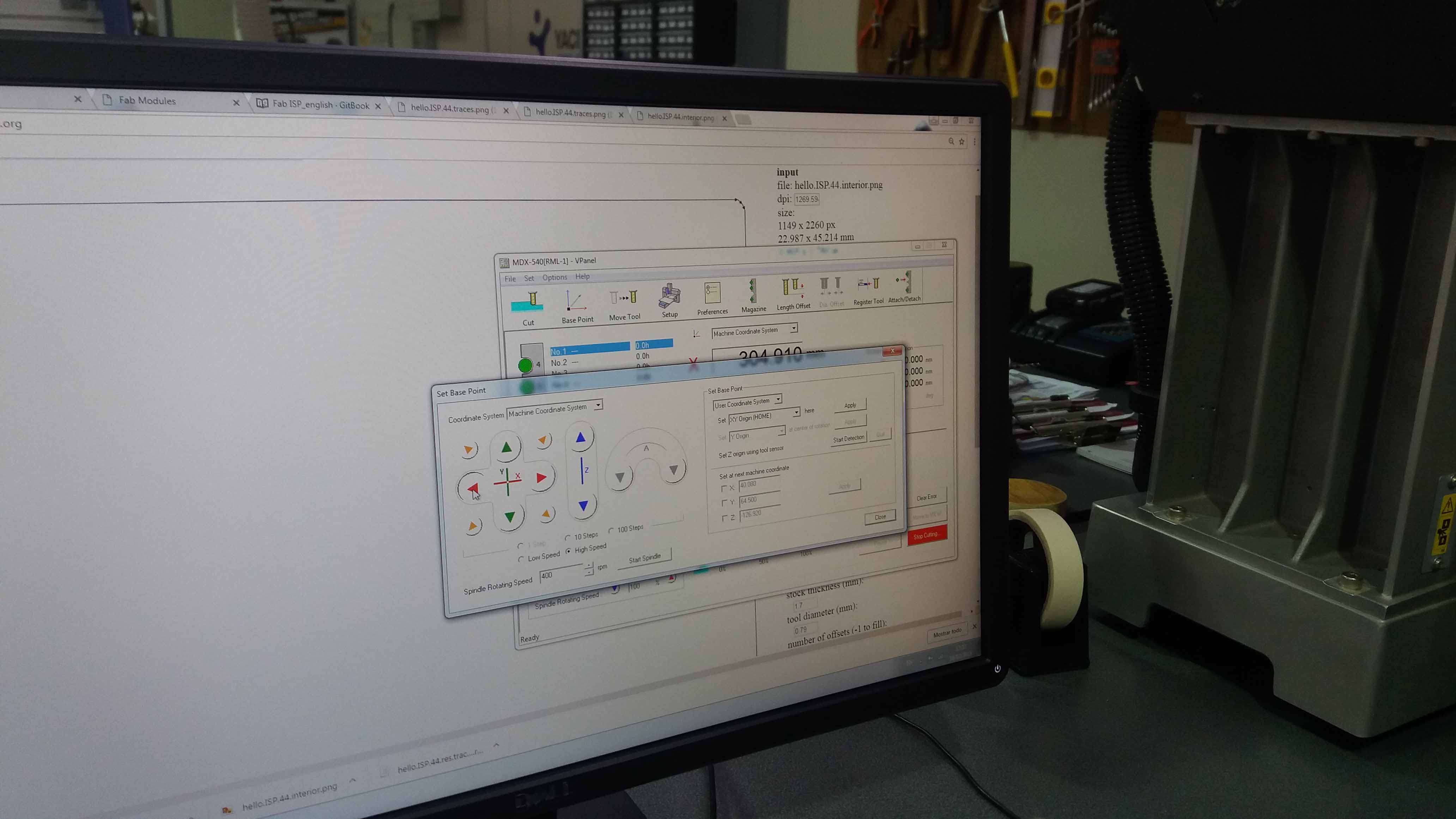
The coordinates should be set now. We locate manually the tool to our desired 0 position (for X and Y axis). Then, we set (reset) the XY position.
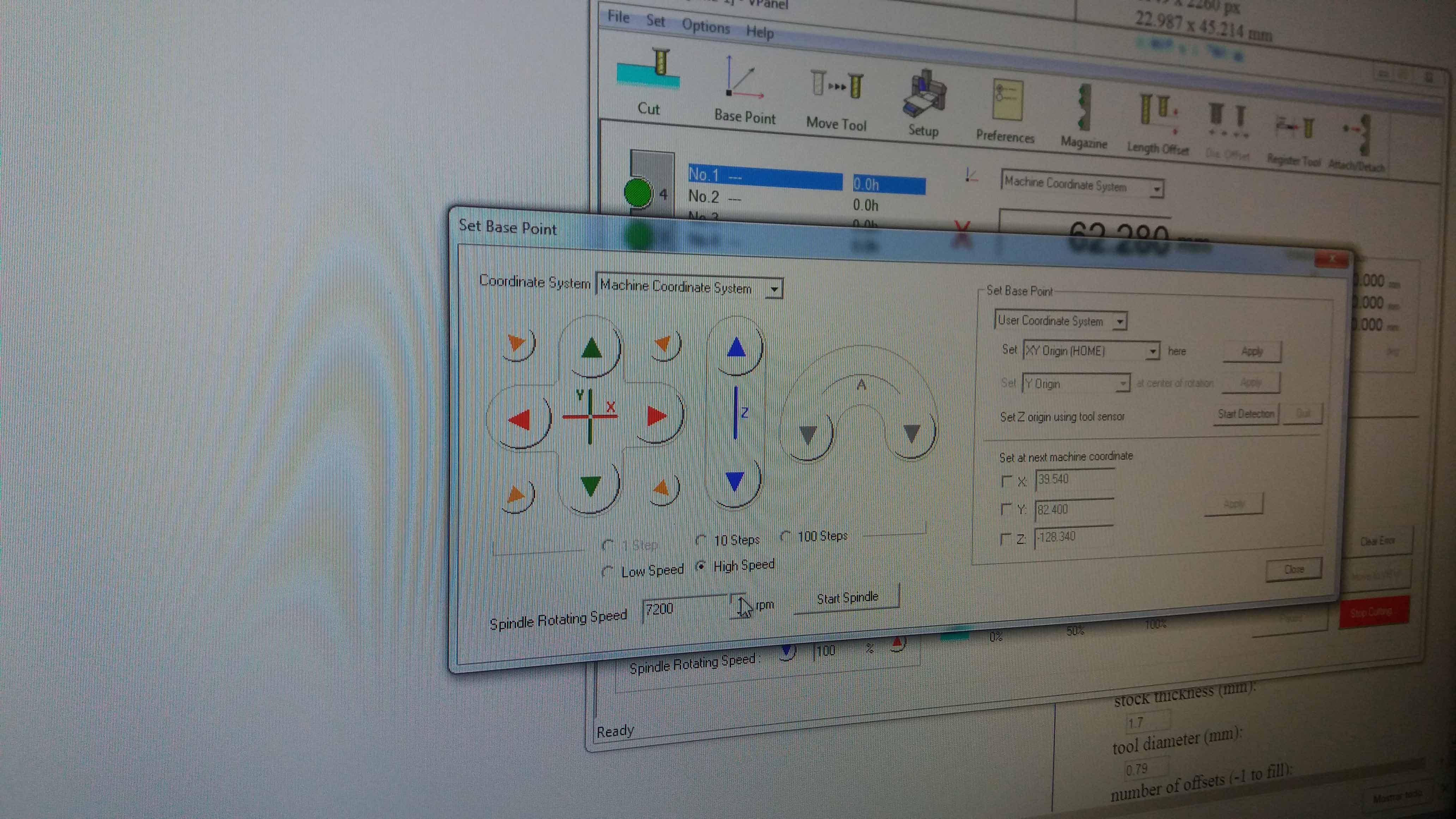
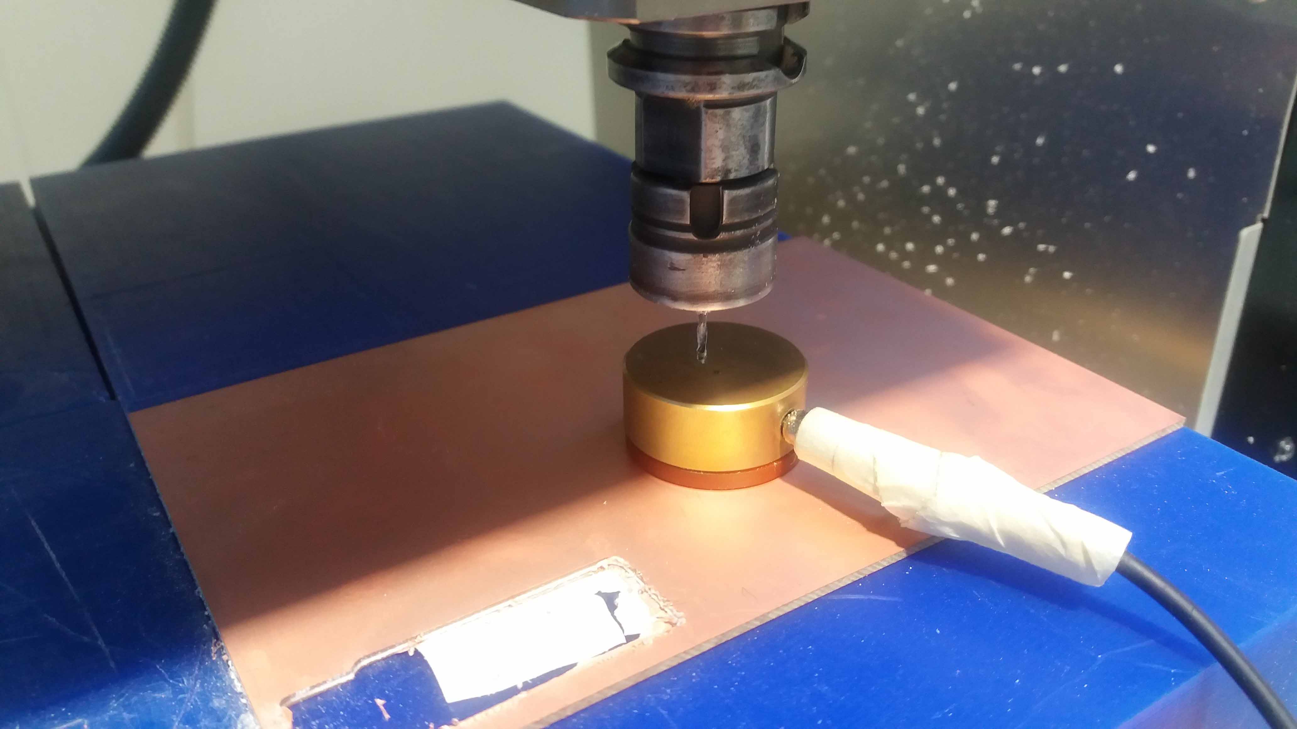
For the z axis, we use a sensor for accurancy. We locate the tool over the sensor.
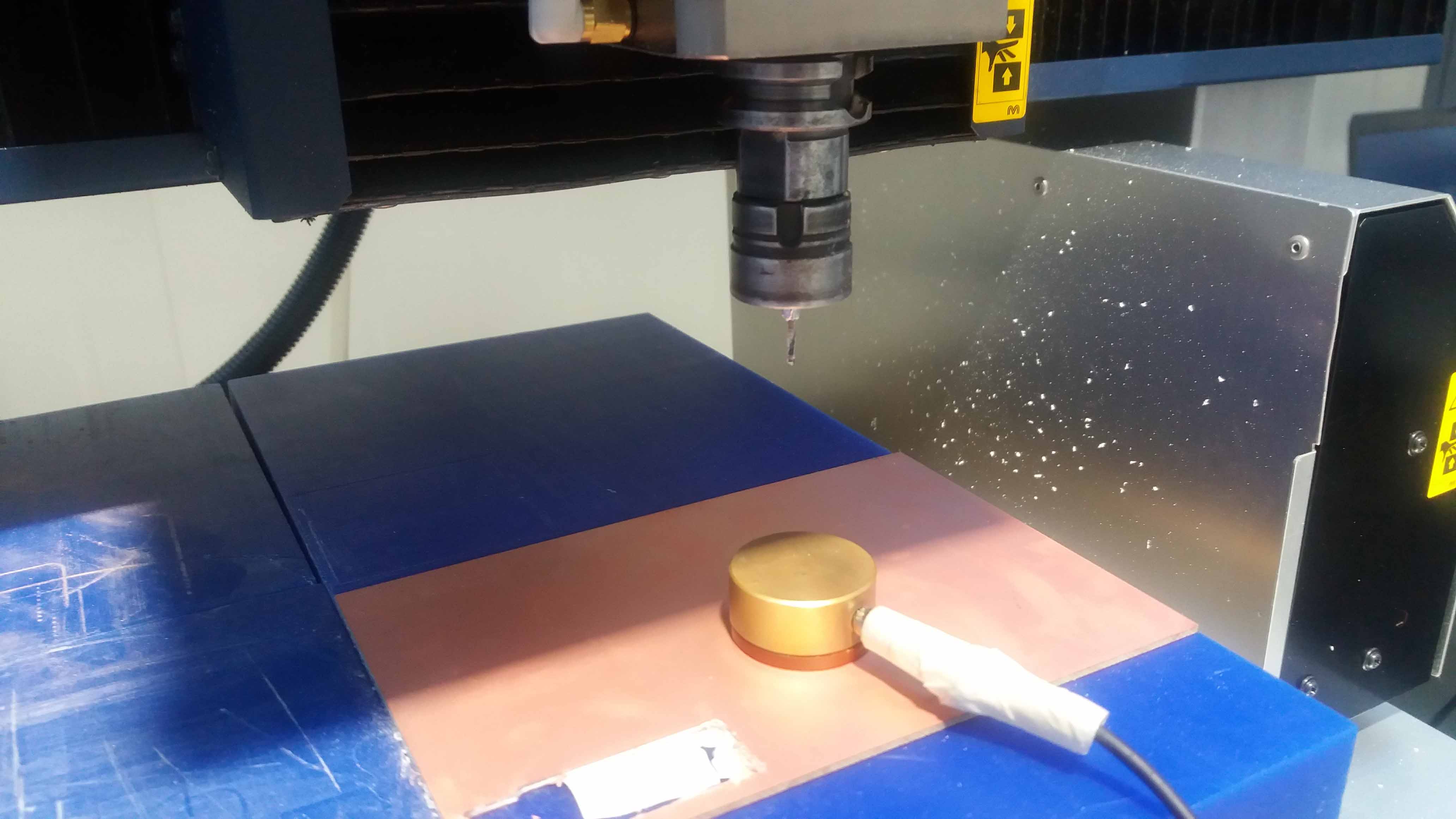
We make sure the sensor is conected. Then we order the machine to measure the z axis. It will move down slowly...
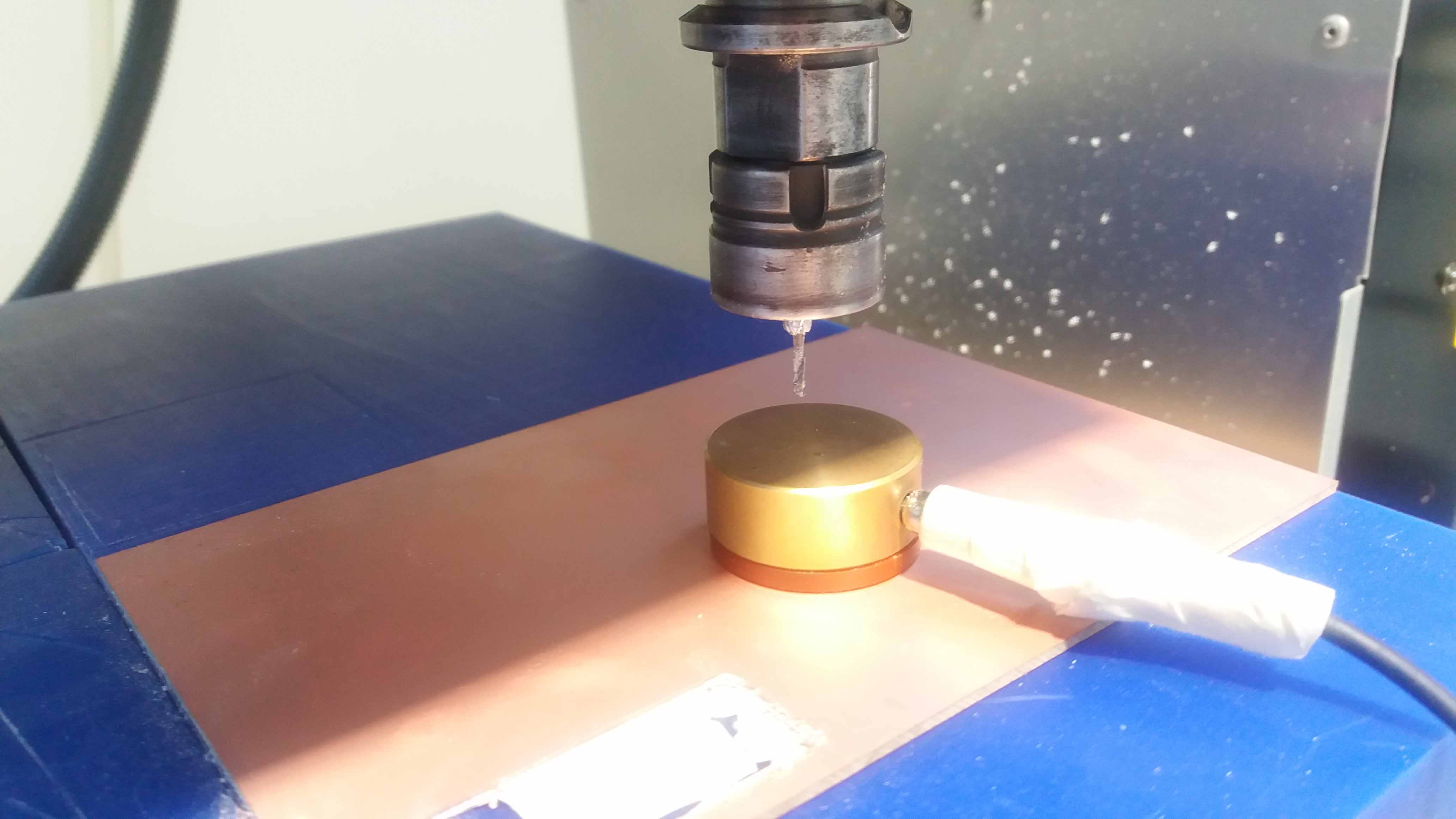
...until it touches the sensor. Then, it will move up again. The z distance will be registered.
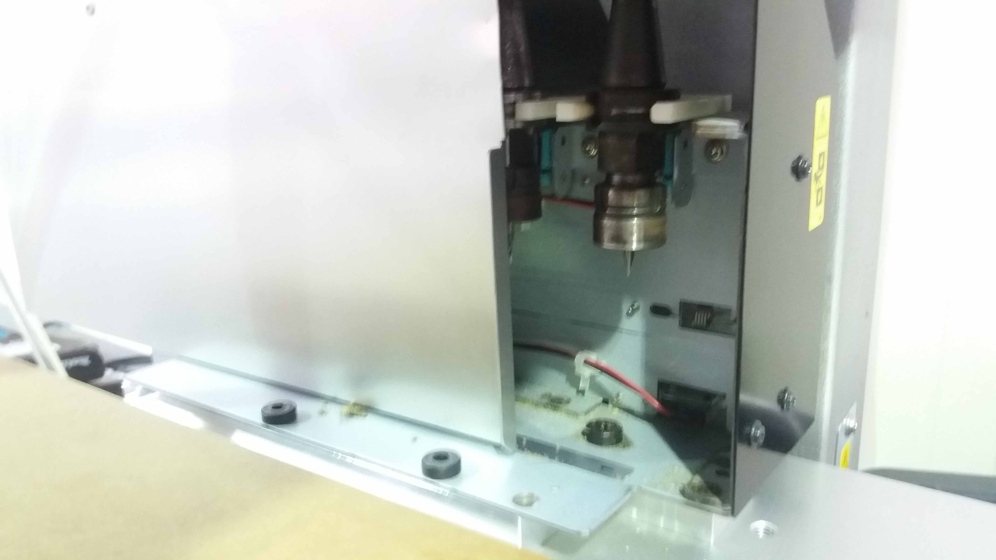
According to the job we make, we chose the option to change the tool. Once the command is issued, the machine opens its door and picks the tool (1/64").
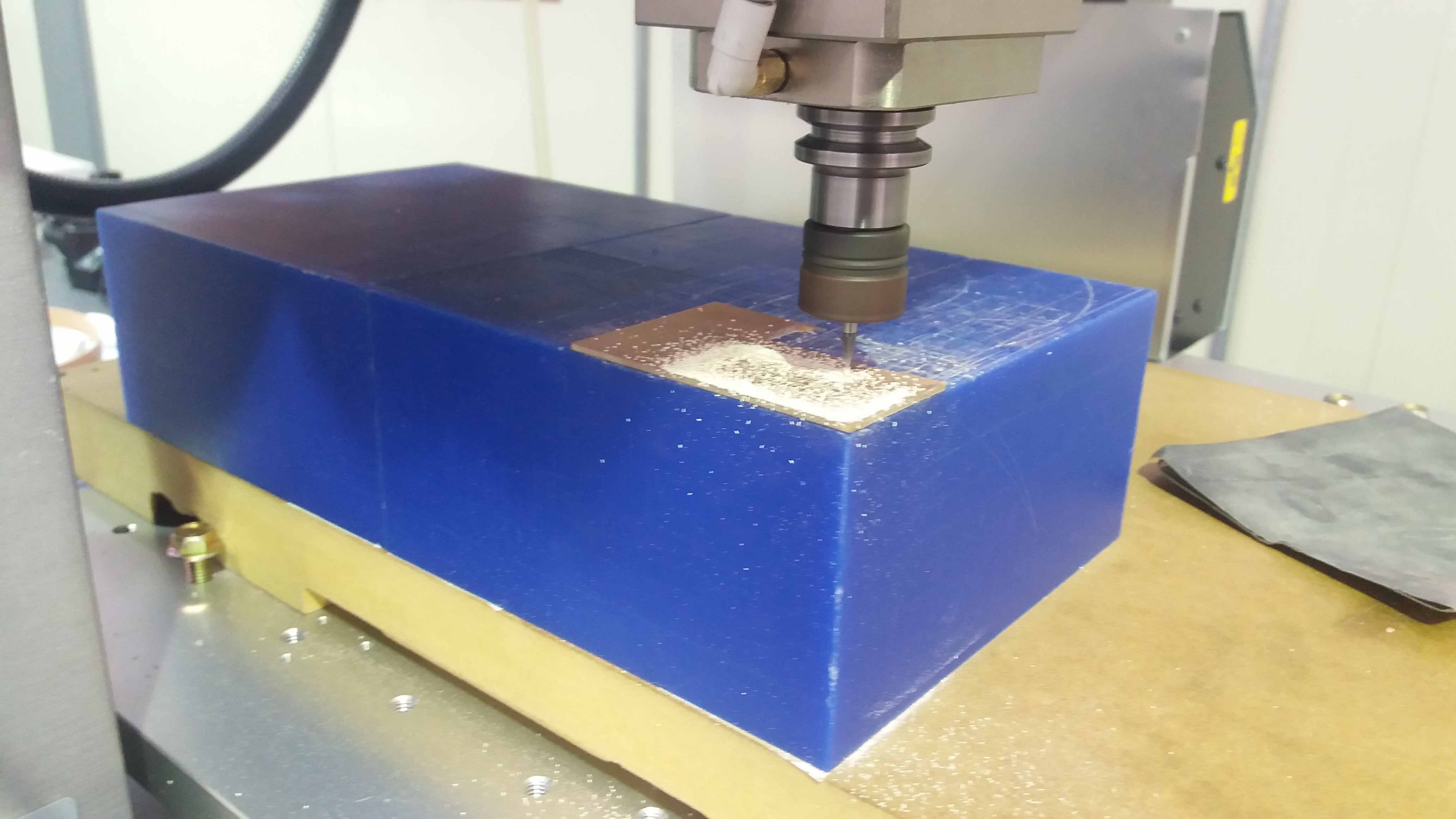
Then, we order the machine to start the job. In this case, it took Aprox. 10 min.
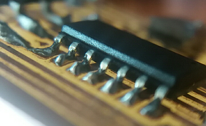
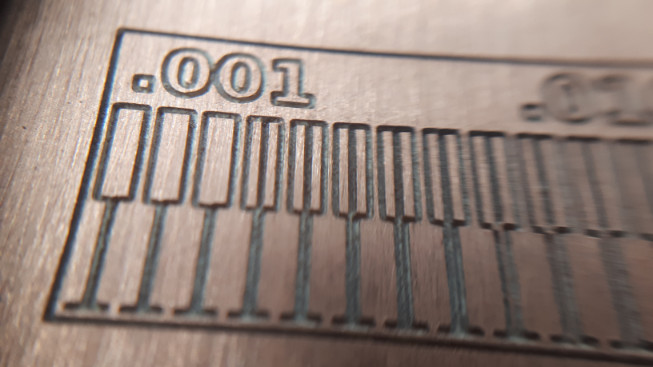
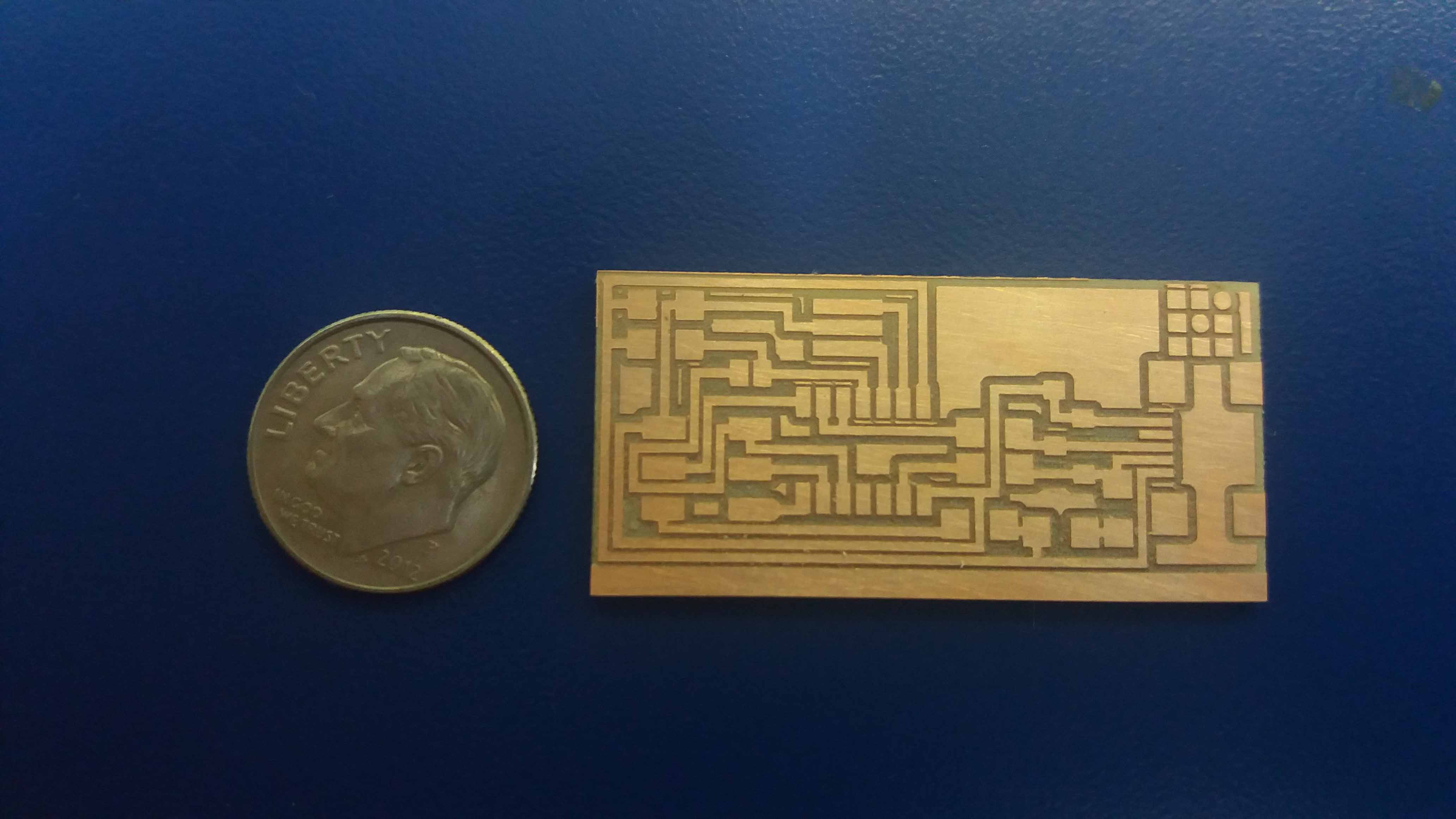
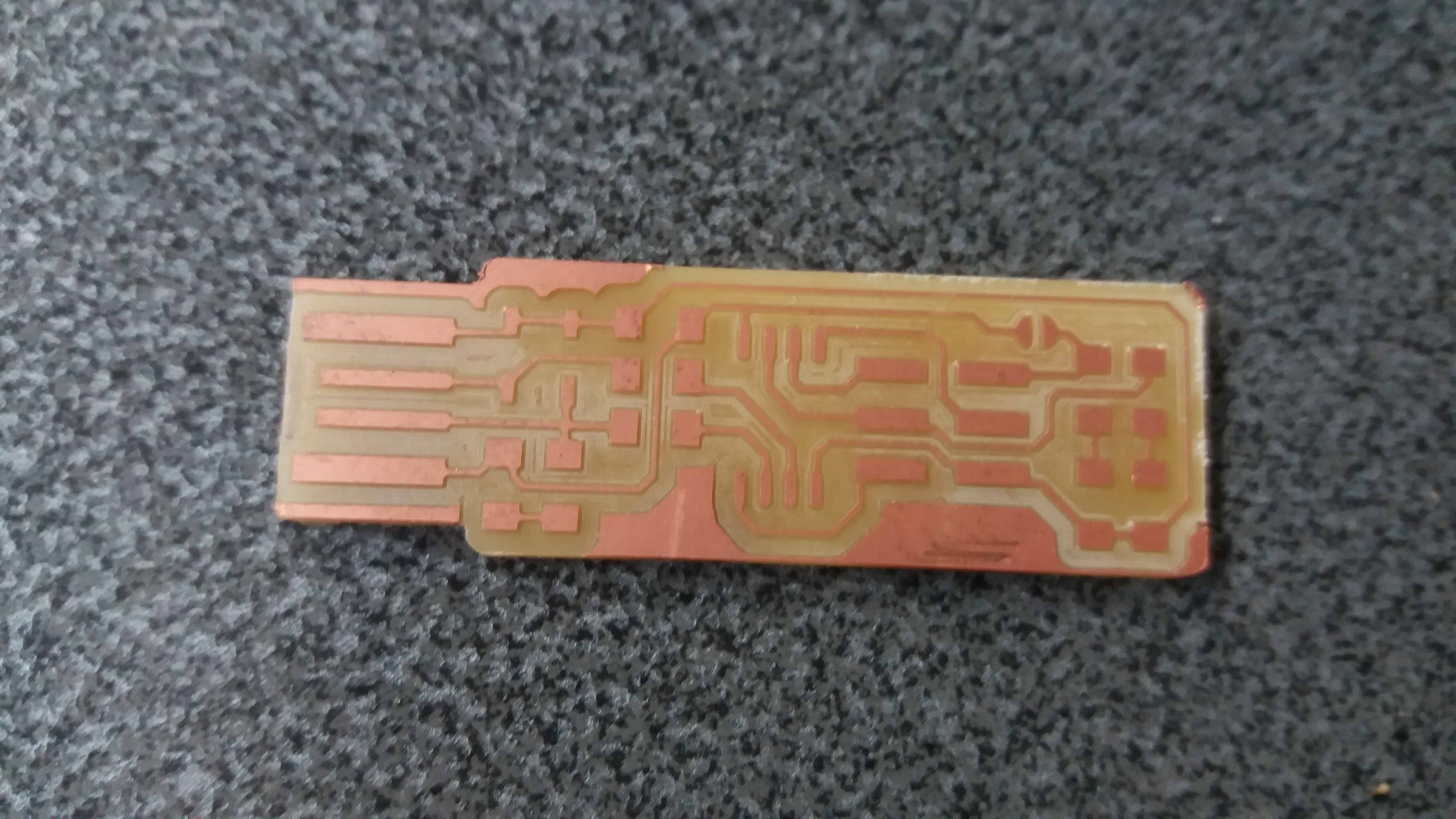
A couple of passes of a fine sand and we are done with the traces.
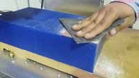
Here is the result (compared with a dollar penny).
Then we proceed with the soldering. The tiny wires that leave the mini usb socket are cleaned using copper braid. Check with the multimeter for false connections or short circuits. Reuse the copper braid to clean up.
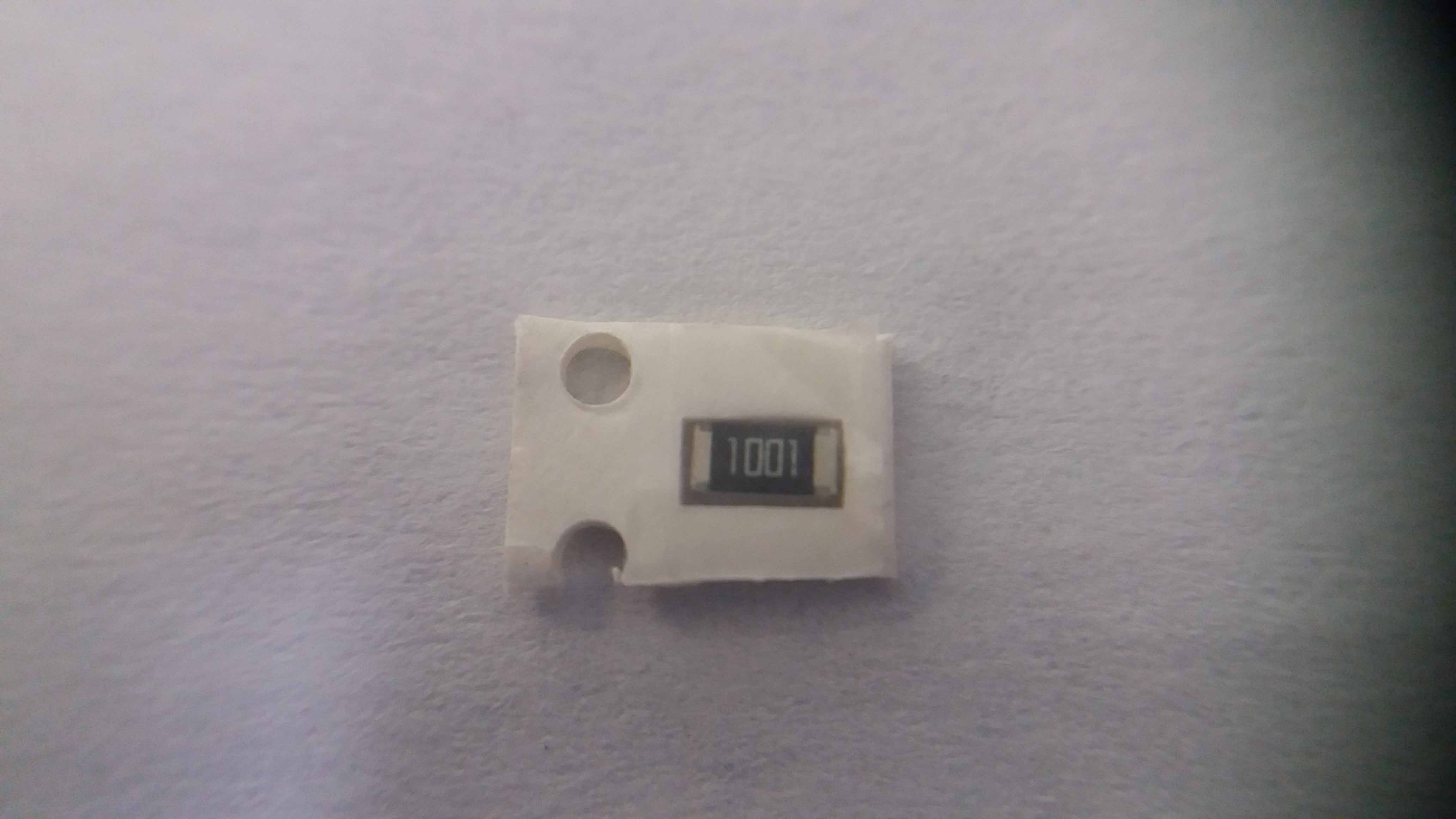
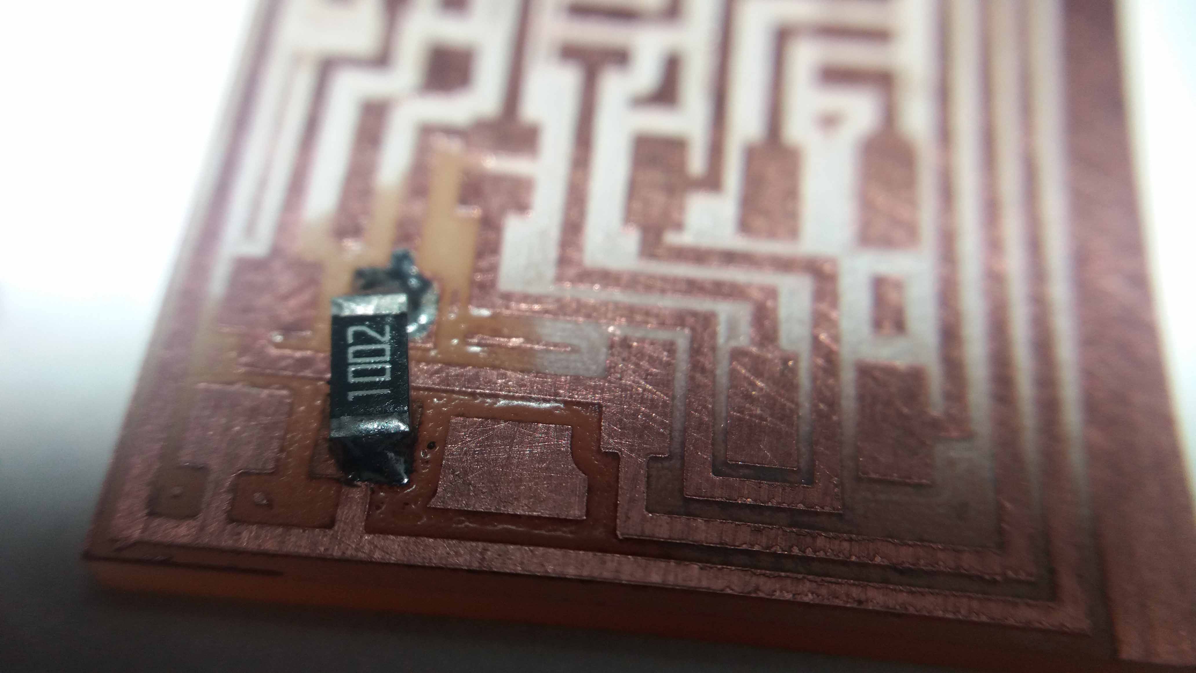
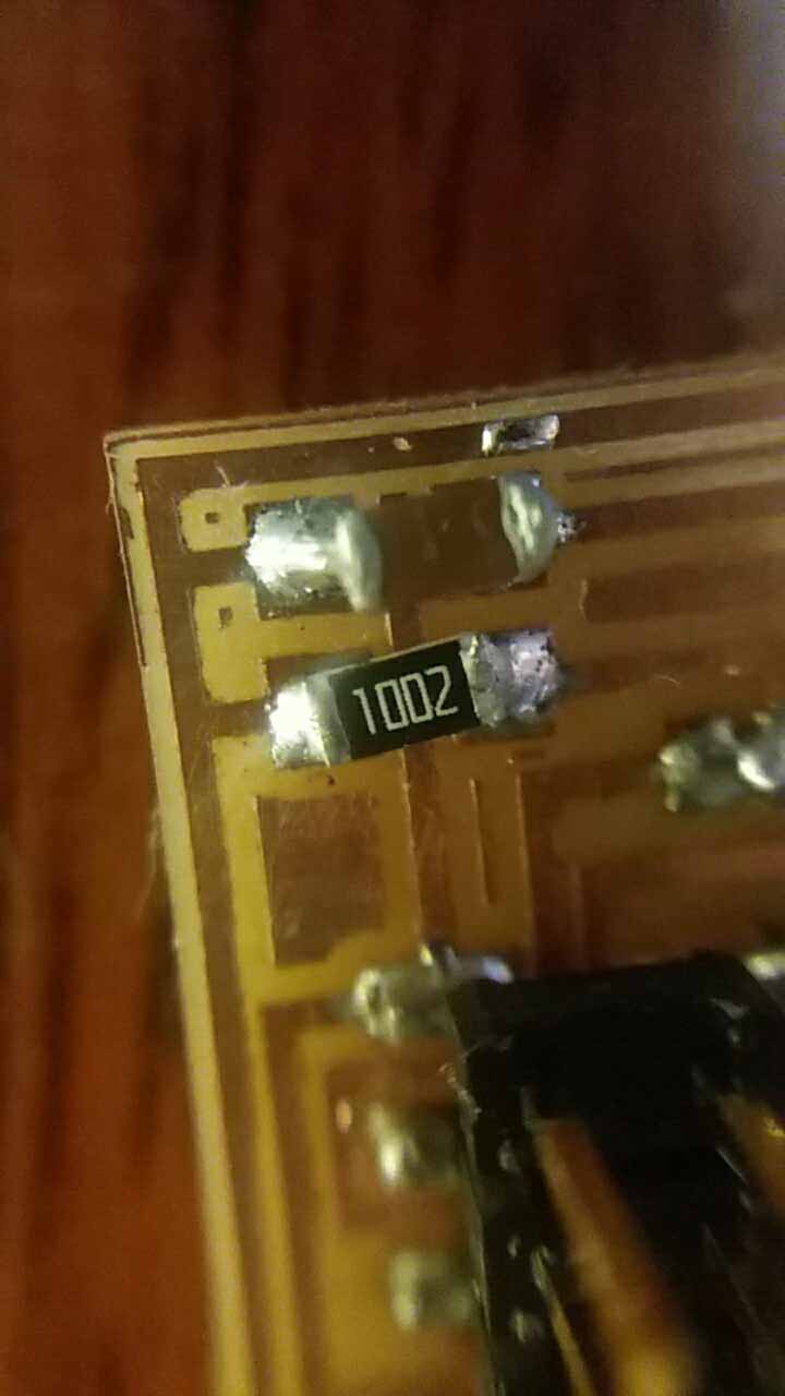
Here is a resistor in it's package.
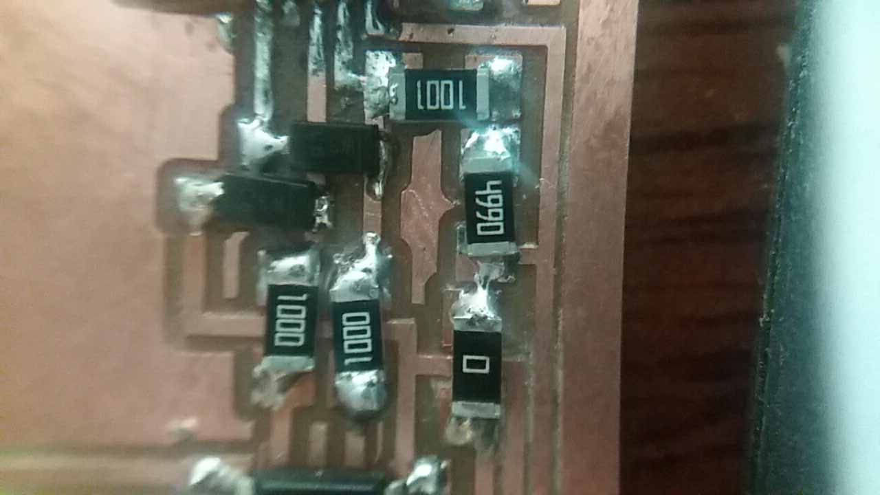
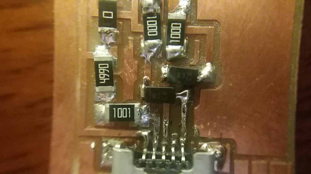
A couple of resistors and a zenner diode soldered to the board.
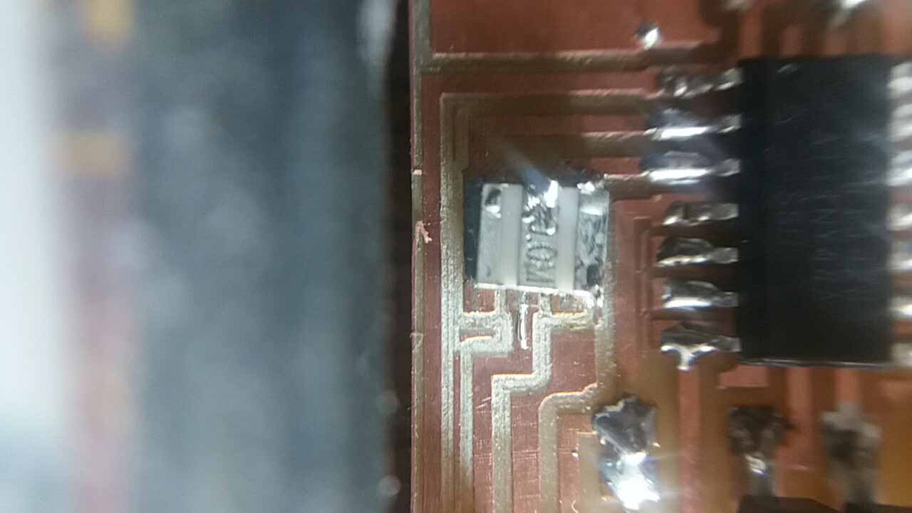
Another resistor soldered.
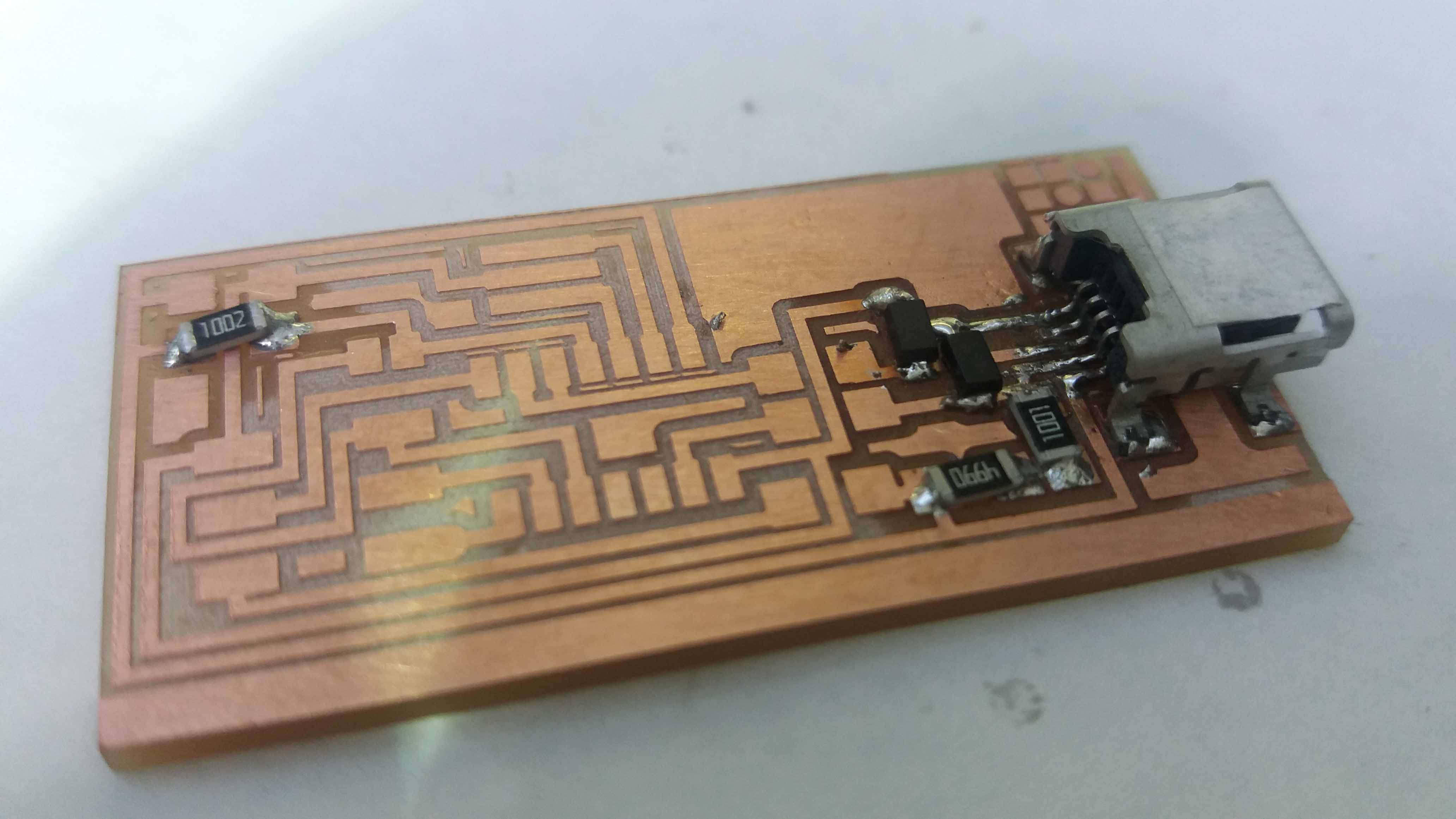
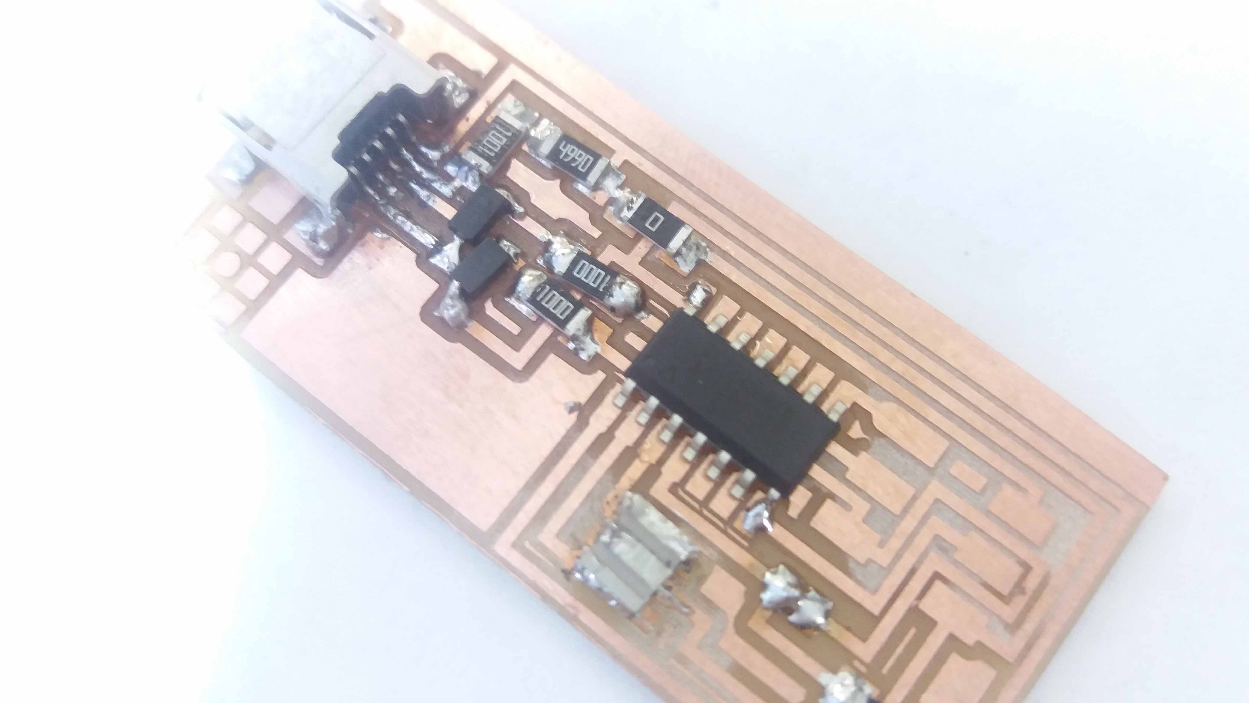
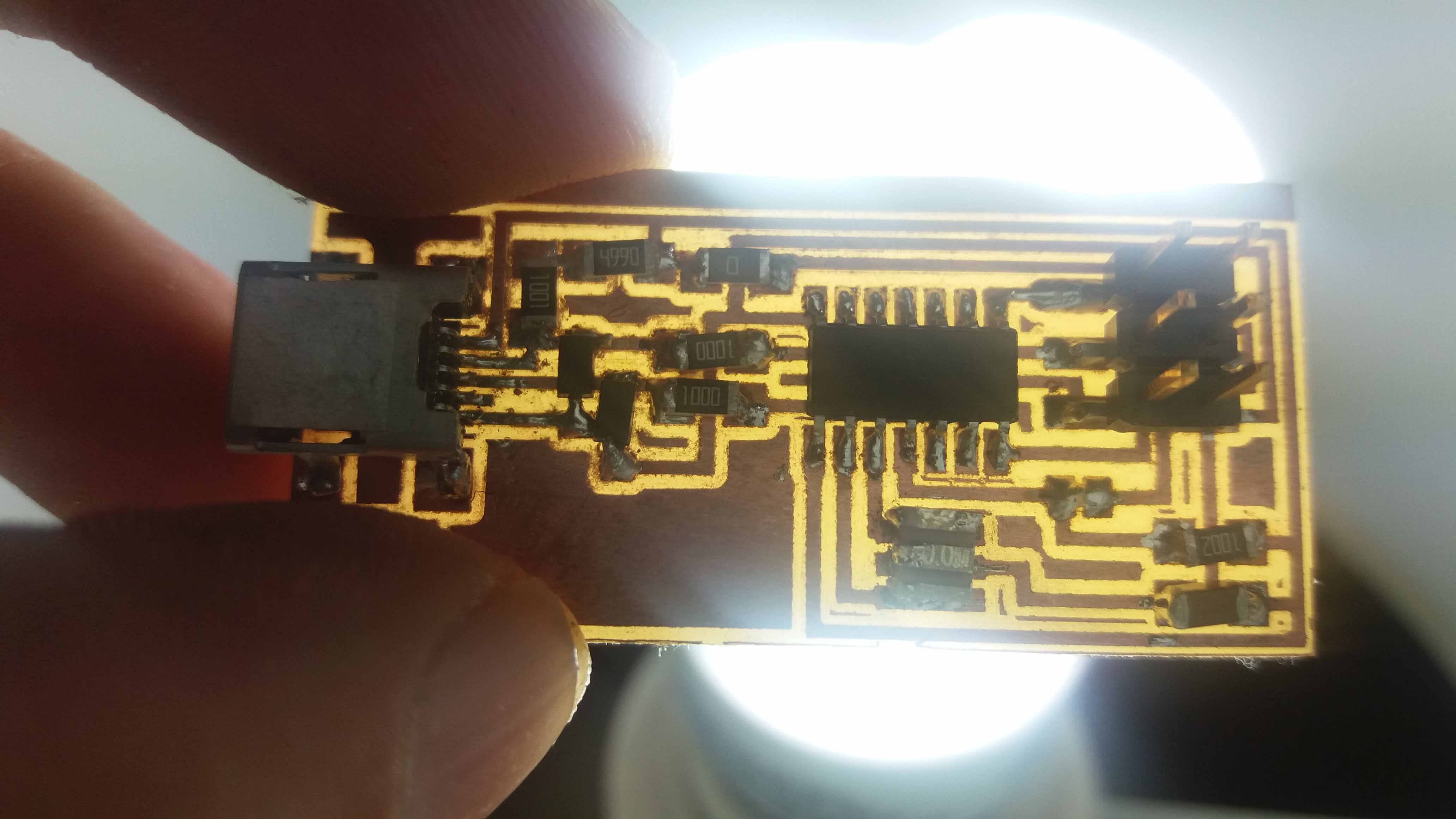
The board so far.
The crystal with soldier. I made a mistake of putting soldier here, instead of the board pads. It will be corrected in the next project.
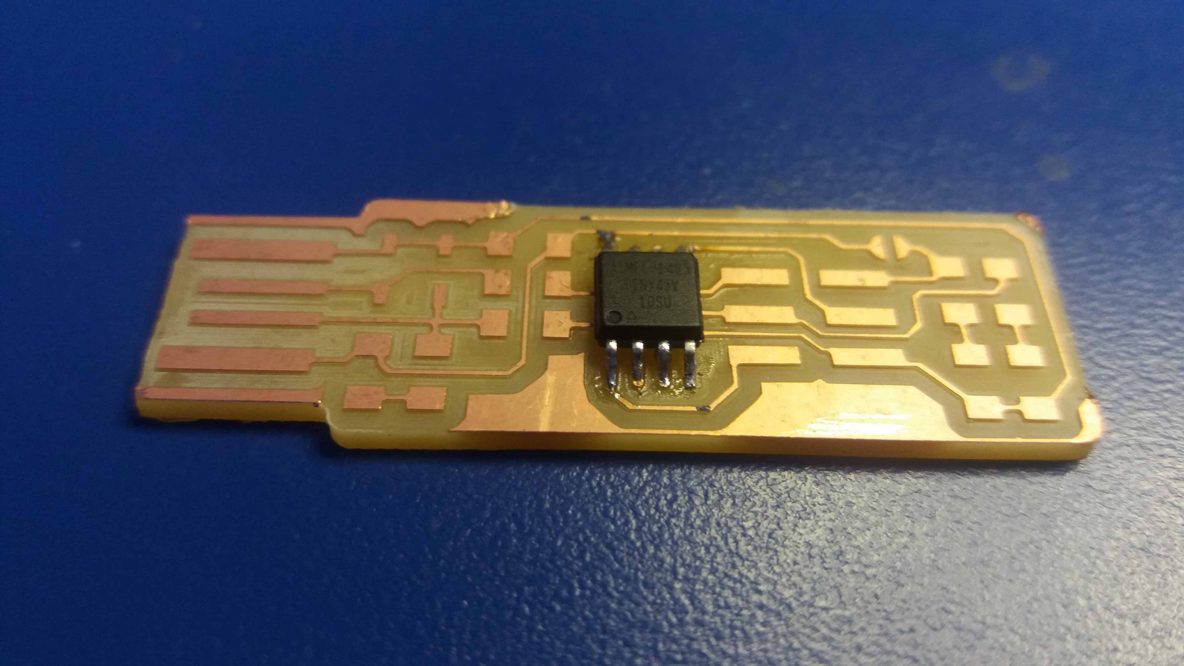
Microprocessor (Attiny 44), and crystal, soldered to the board.
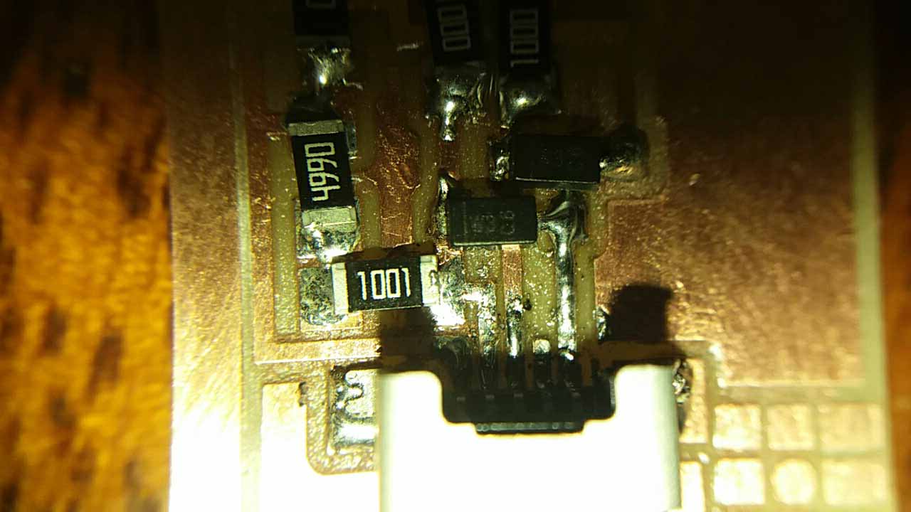
Another close up to check wrong connections. I also tested the connection using a multimeter.
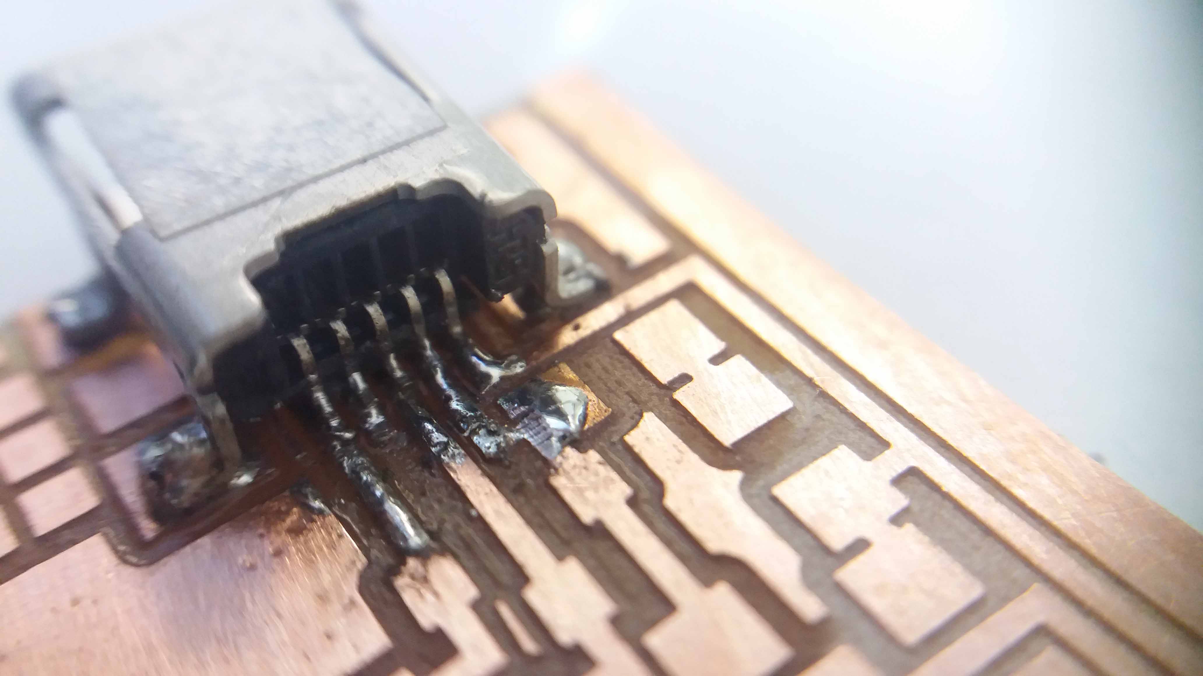
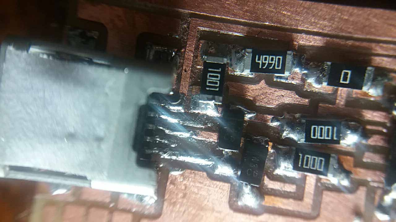
Close up to the usb connection.
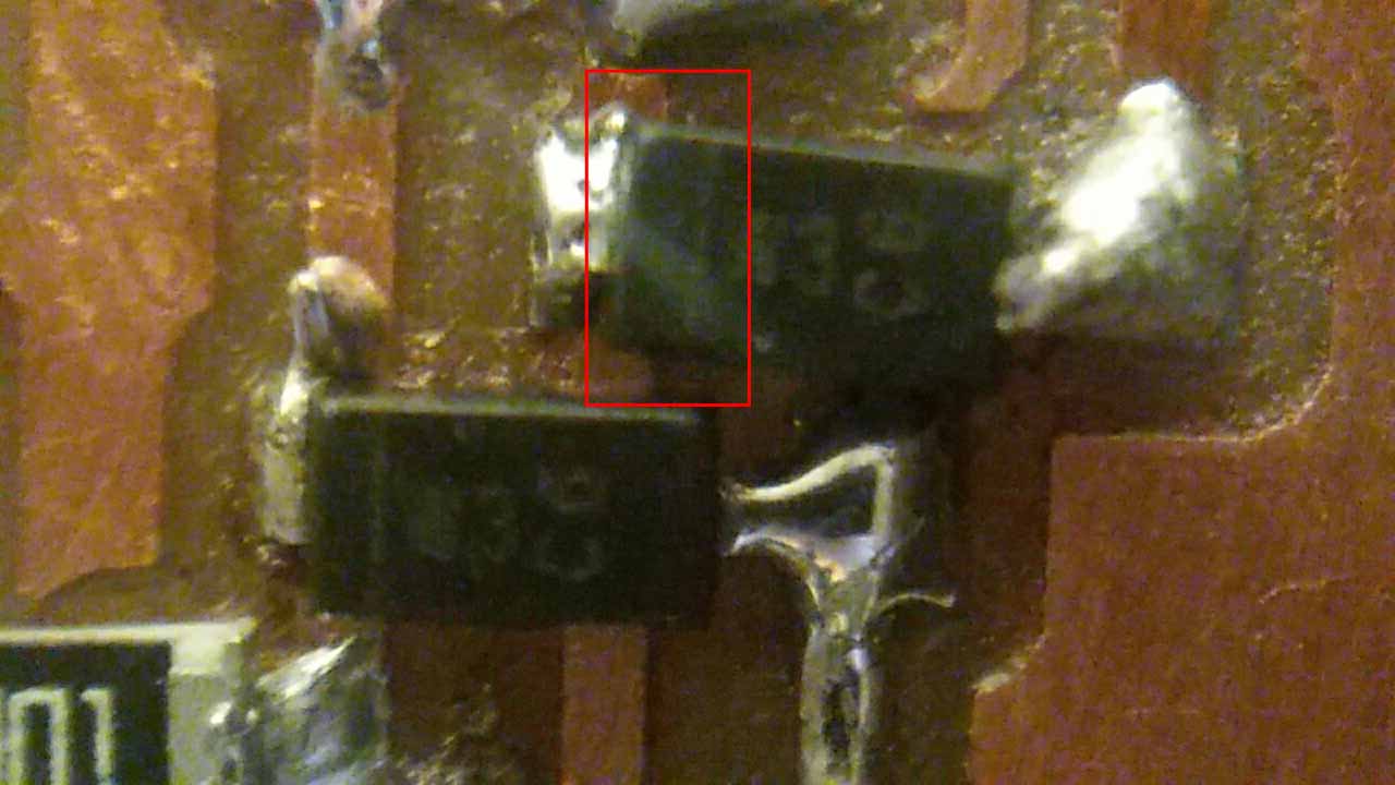
close up to the diodes. Remember that they have polarity.
A litle line in the diode marks the catode (negative side). Hard to see after the soldiering, but is marked in red to make it clear.
Another close up for checking. The crystal have two resitors embeded in one piece (that's why we didn't include them).
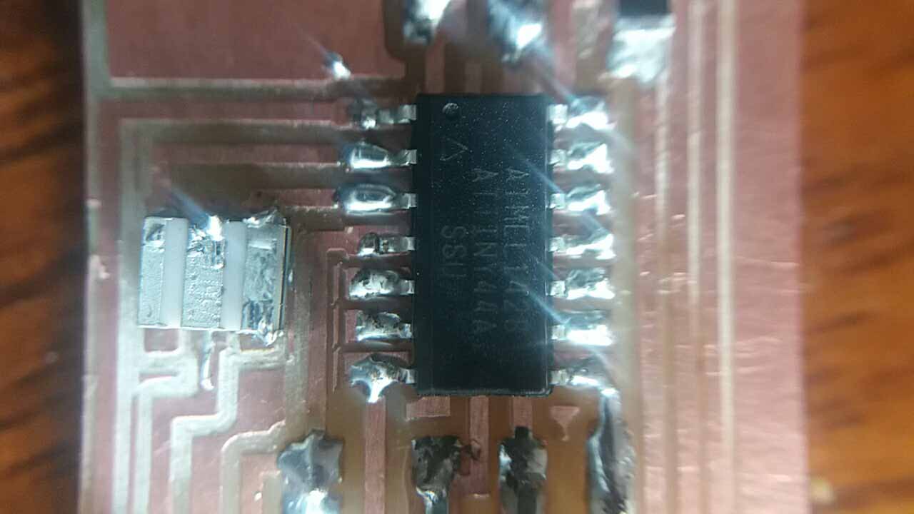
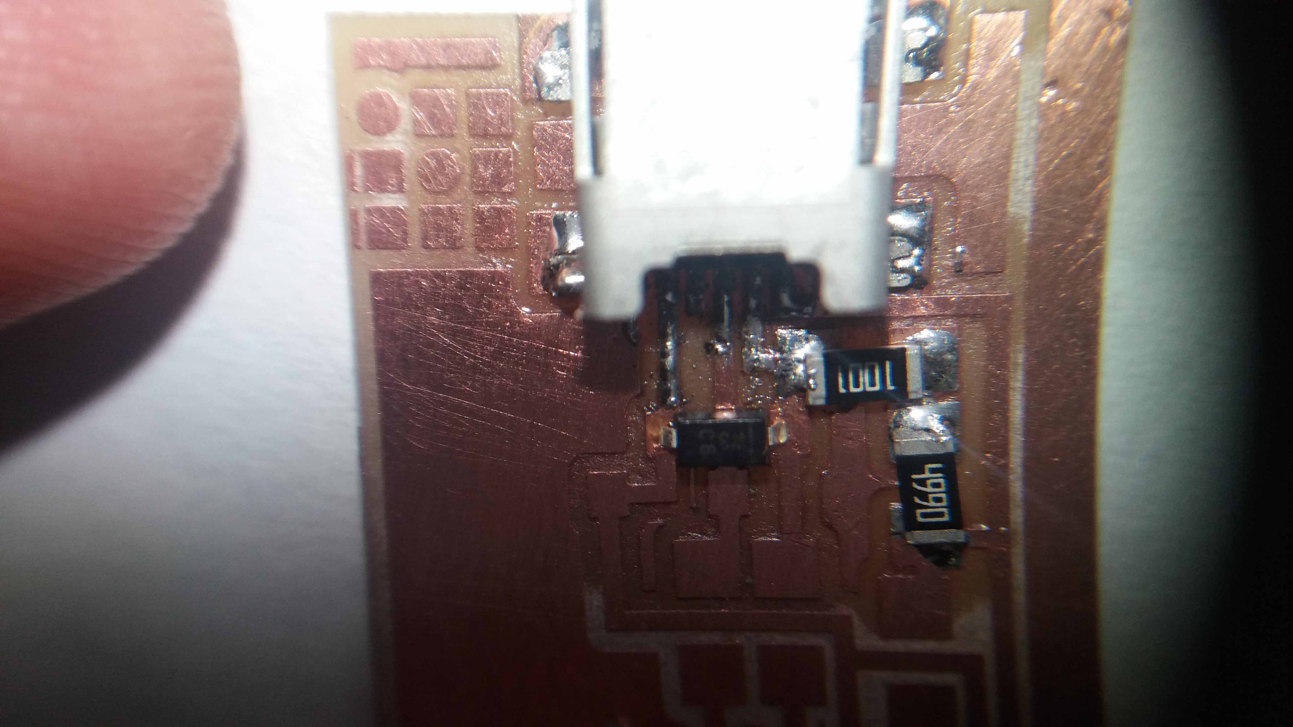
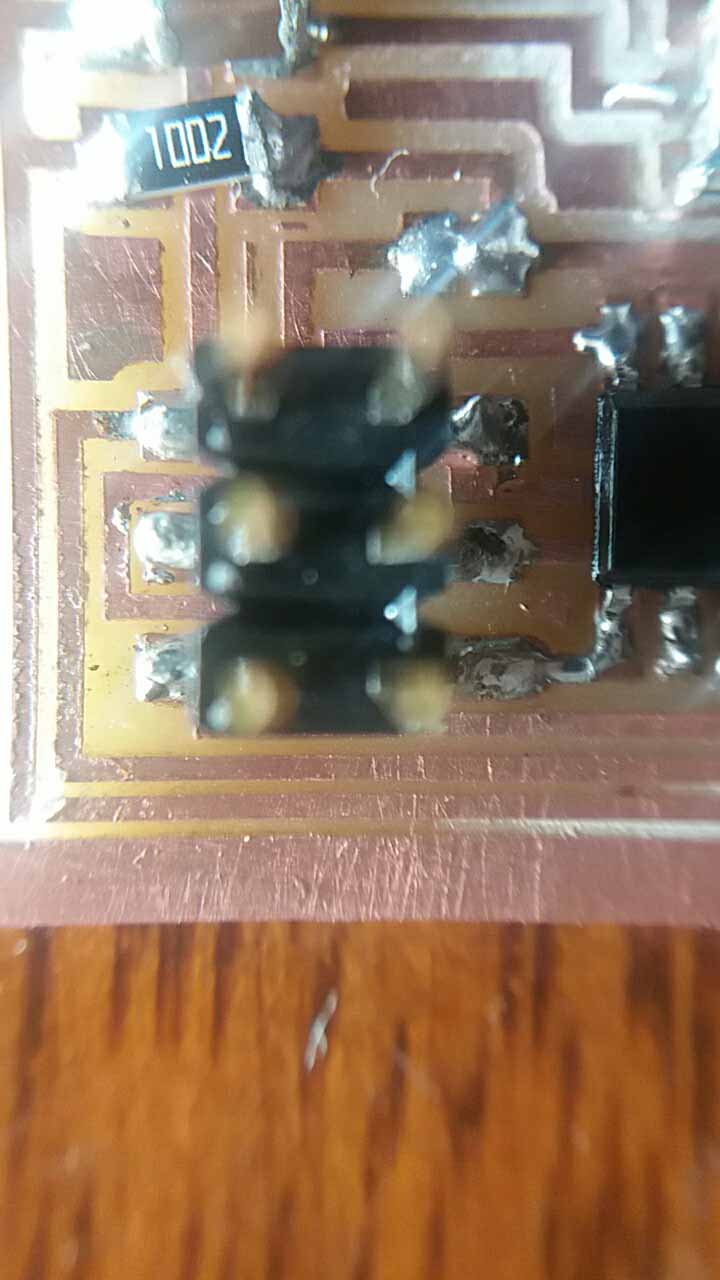
Connections to the microcontroller chip.
In this image we can see the resistor "bridging" a line of copper. We need to have special care not to let soldier slip under it. We can see also a capacitor that serves the crystal.
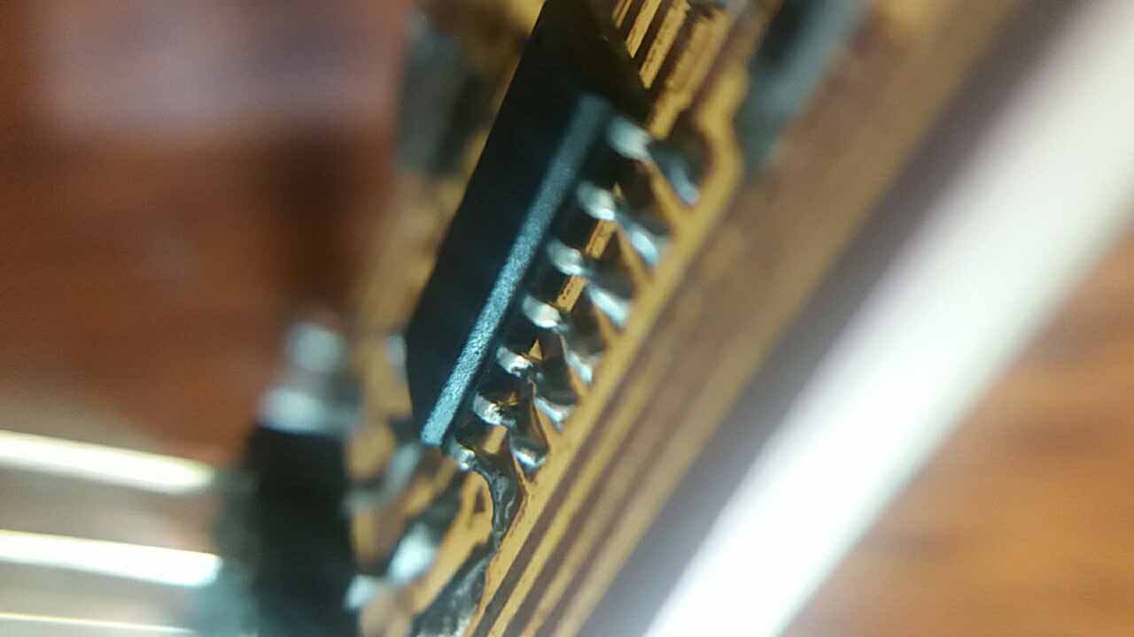
We check now the programmer pins...
The chip against the light.
Then, I tested the software to programm it. All the instructions where followed, but no luck. Looks like some models are not backward/compatible, so it is neceessary to test with previous versions. With a few new versions to test, plus testing the combinations of them, the time to spend in this testing was not enough to advance in the assigment and in the FabAcademy schedulle.
Update
After lots of trials and errors, the board never worked (could not be programmed). In order to advance, I change the approach, and build a new programmer. I wanted to try the first board, but as a matter of testing and complete the assigment, I switched to the programmer FabTinyISP. Here is the process of building:
Soldering the microprocessor...
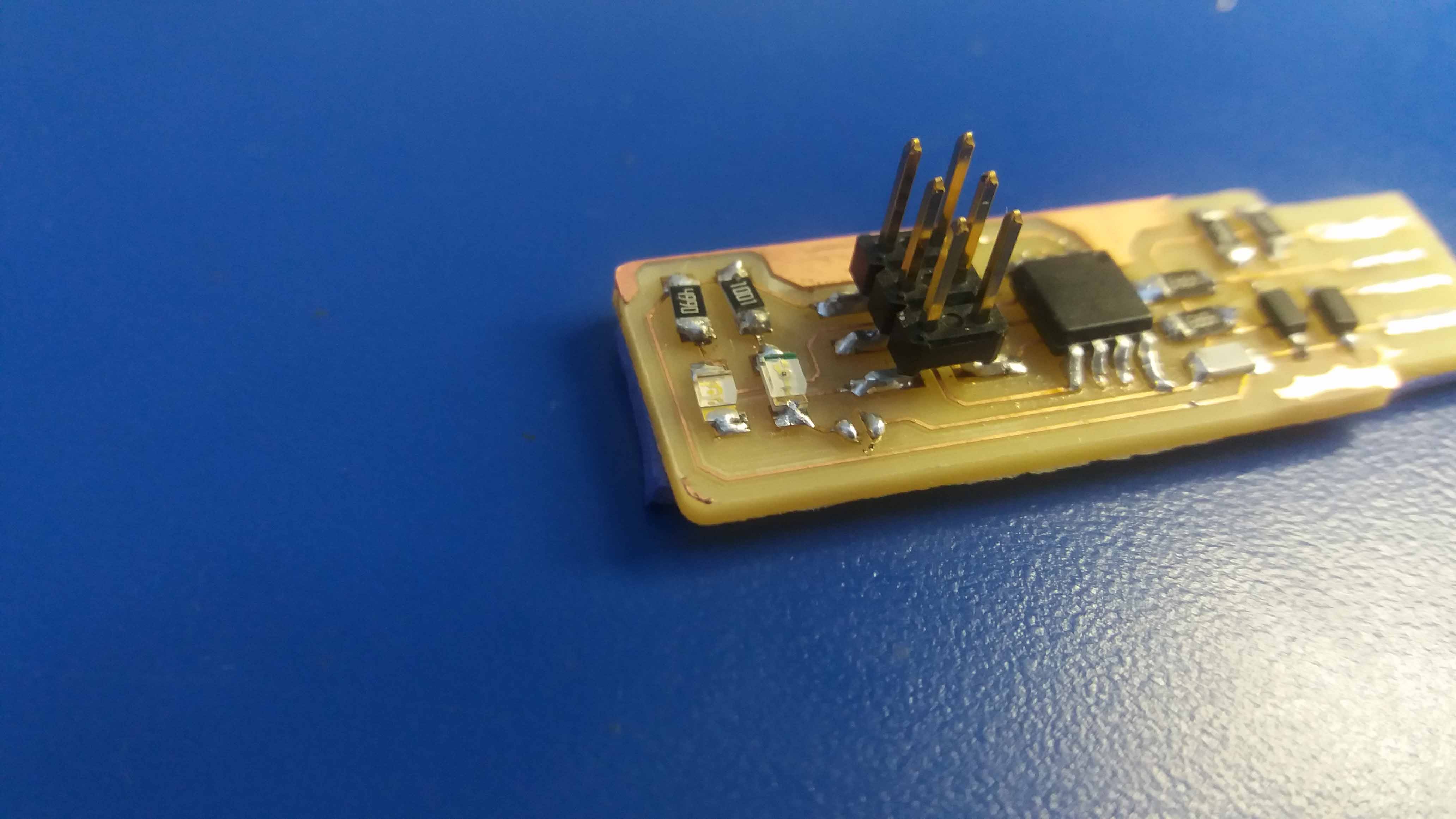
A few more parts...
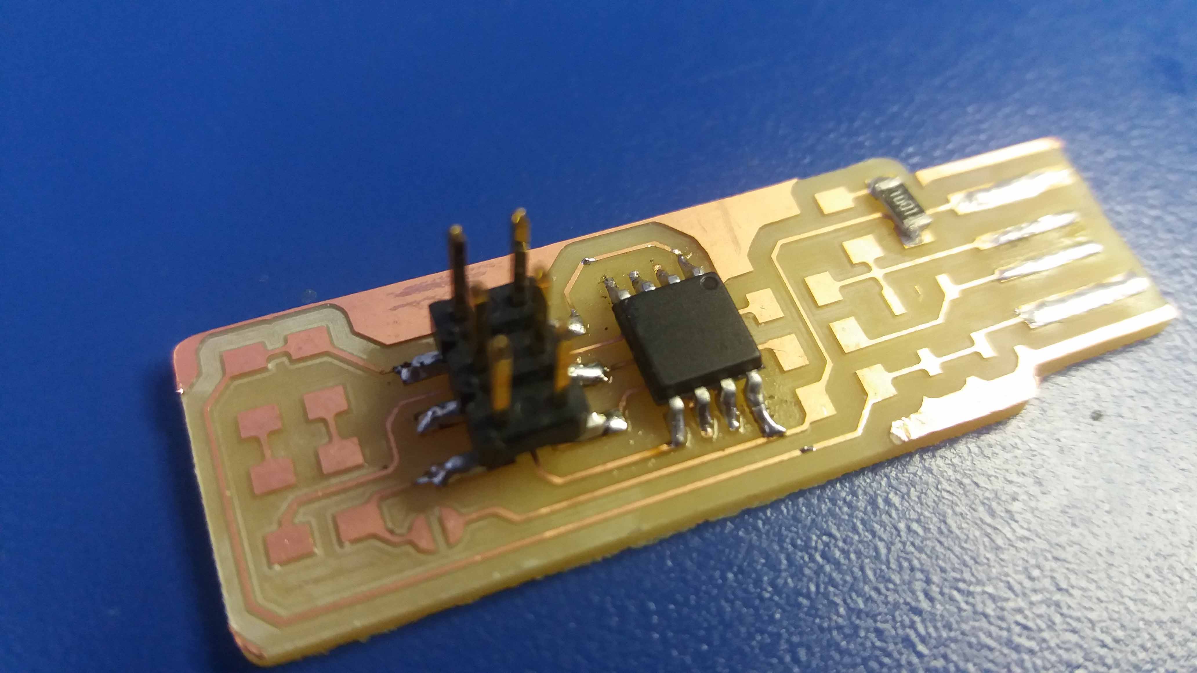
And the device completed.
Programming. Problems and solutions
After double checking the conections for shorts, false conctacts and gaps with the multimeter I proceeded with the software installation.
Thanks to the help of my friend Eduardo Cartagena, I finally made the board work following his documentation, also based on Brian Tutorial.
First we need to install git. I had it already installed and it didn't present any problems. In case it's needed, the link is here.
After the tutorial, I had the problem of the board not beeing found.
Installing Atmel Studio 7 solved the problem. This was necessary because the programm have some drivers that the board needs.
Once it is done, we install GNU Make.
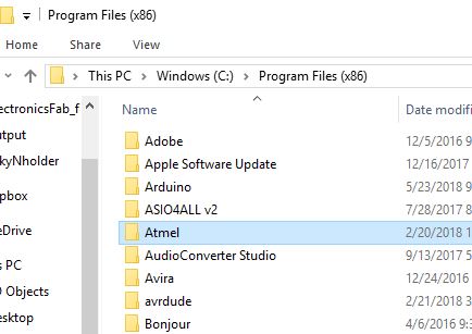
Then, we download the avrdude program from this link, unzip the file and copy the folder inside C://Program Files (x86).
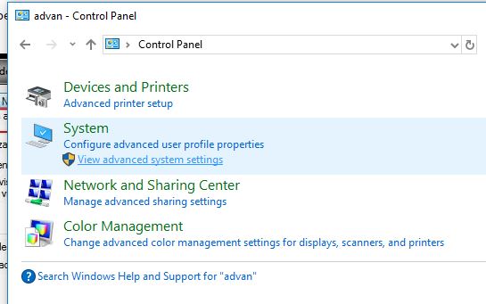
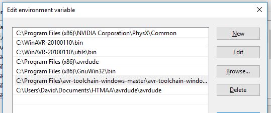
Then, we update the system paths to our environment variables. They are found in Control panel --> View advanced settings...
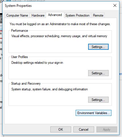
...and then, under "Advanced" tab, clic in "Environment Variables".
Select the "path" system variable, and clic "edit".
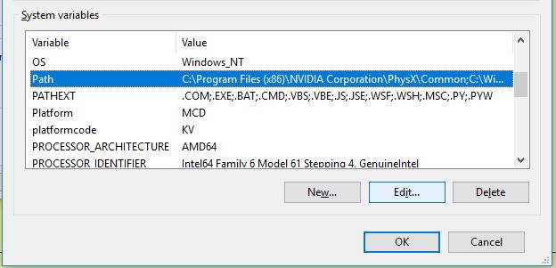
Then, we use the "new" button to add the paths. The paths to be linked are for the location of the programs avr-toolchain-windows-master, GnuWin32 and avrdude.
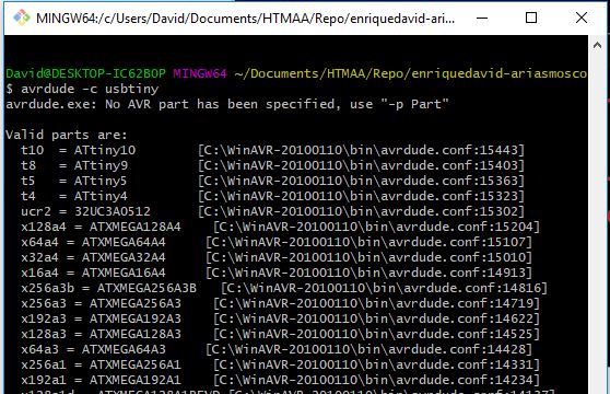
Then, from the gitbash console we type the command "avrdude -c usbtiny". This will show the list of the potencial programable chips.
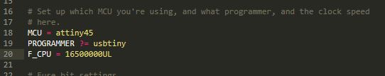
We open the Make file using a text editor. I used Sublime Text, because I like the format and colors it shows, but any would do. As I am going to use the usbtiny as a programmer, I leave it as it is.
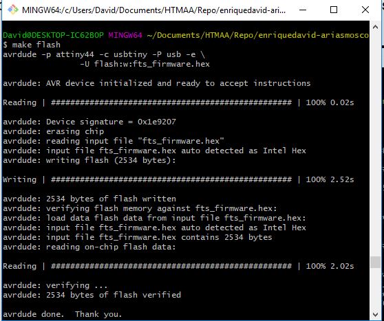
Then, we connect the devices, open the gitbash from the location where it was saved, and run "make flash".
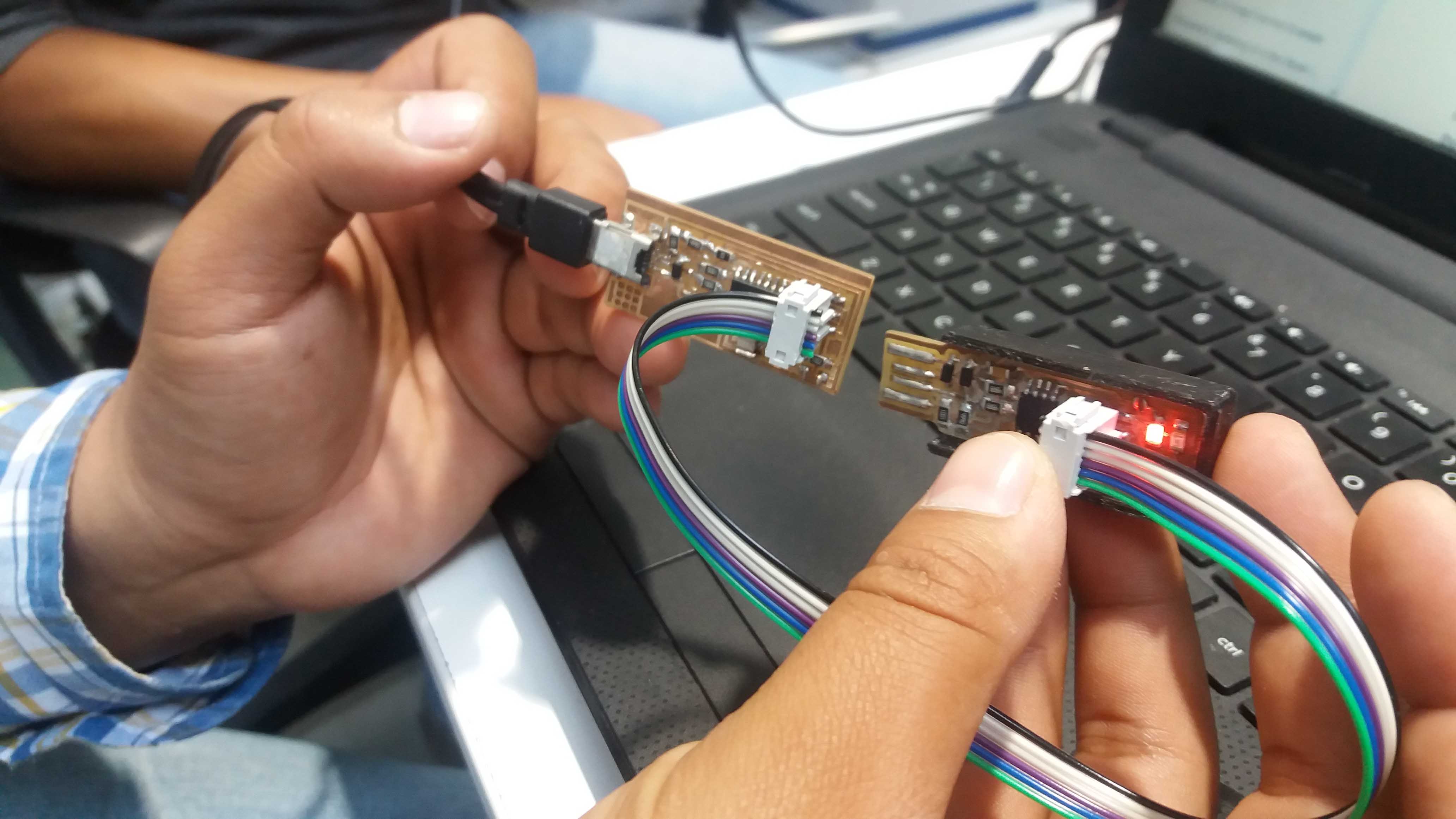
Everything looks fine.
Finally, we run "make rstdisbl". This will disable the reset, and the board will be not able to be programmed again. The last part is to break the bridge in our board, and the programmer is ready.

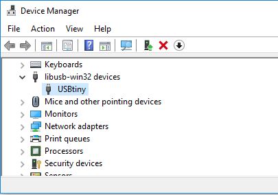
At this time we can check if the system recognizes the board. We open the device manager and we found it there! Under the name "USBtiny".
The files used in the making of this device are found here:

This work is licensed under a Creative Commons Attribution 4.0 International License.