CNC can deal with big motors too. Here is an example of what we can do.
Workflow:
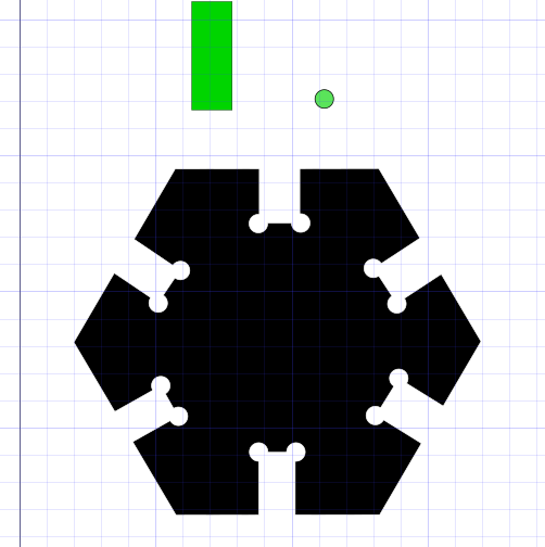
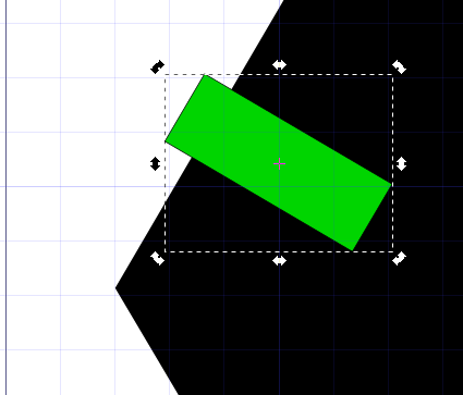
Inkscape will be used to draw this probe. First, I draw an hexagon. Also, a couple of objects (in green) that I'm going to use for cutting (boolean sustracting) digital material.
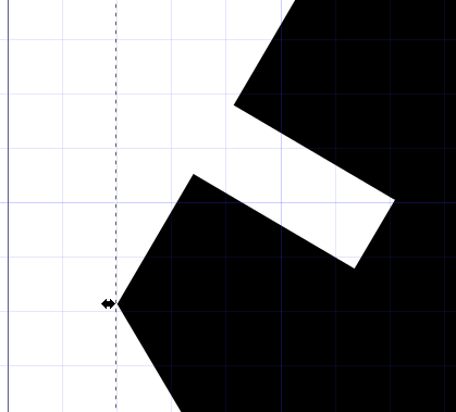
Here we can see part of the material cut away by the green tool.
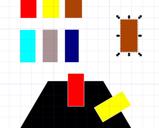
Other tools with slightly diferent width each are created.
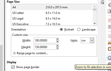
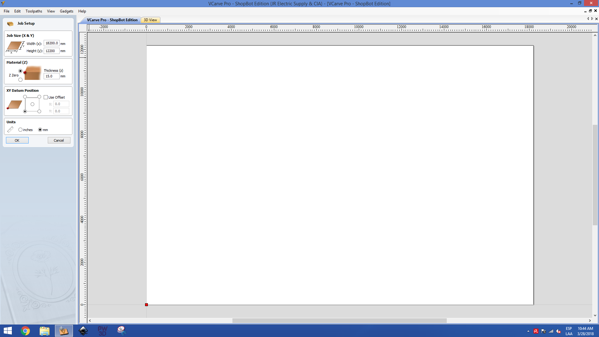
Setting the workspace for the bed size
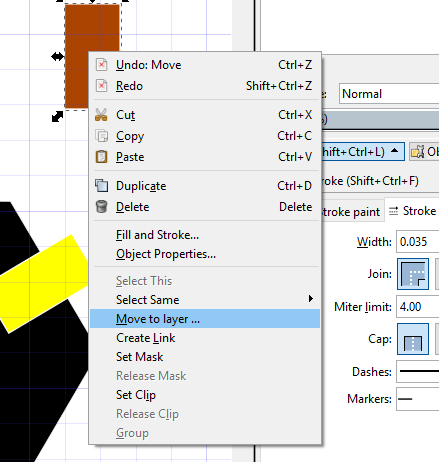
Objects can be moved between layers.
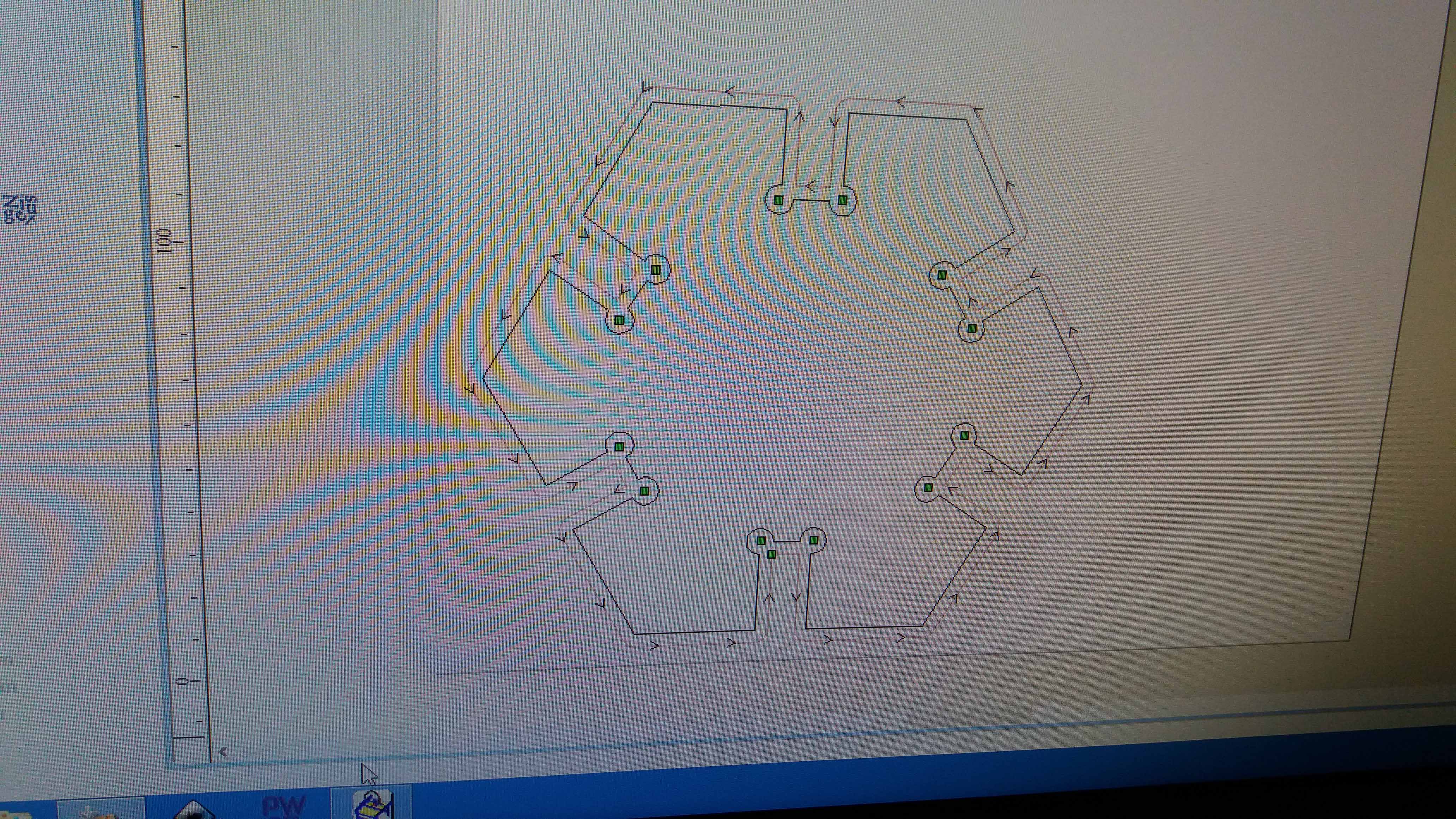
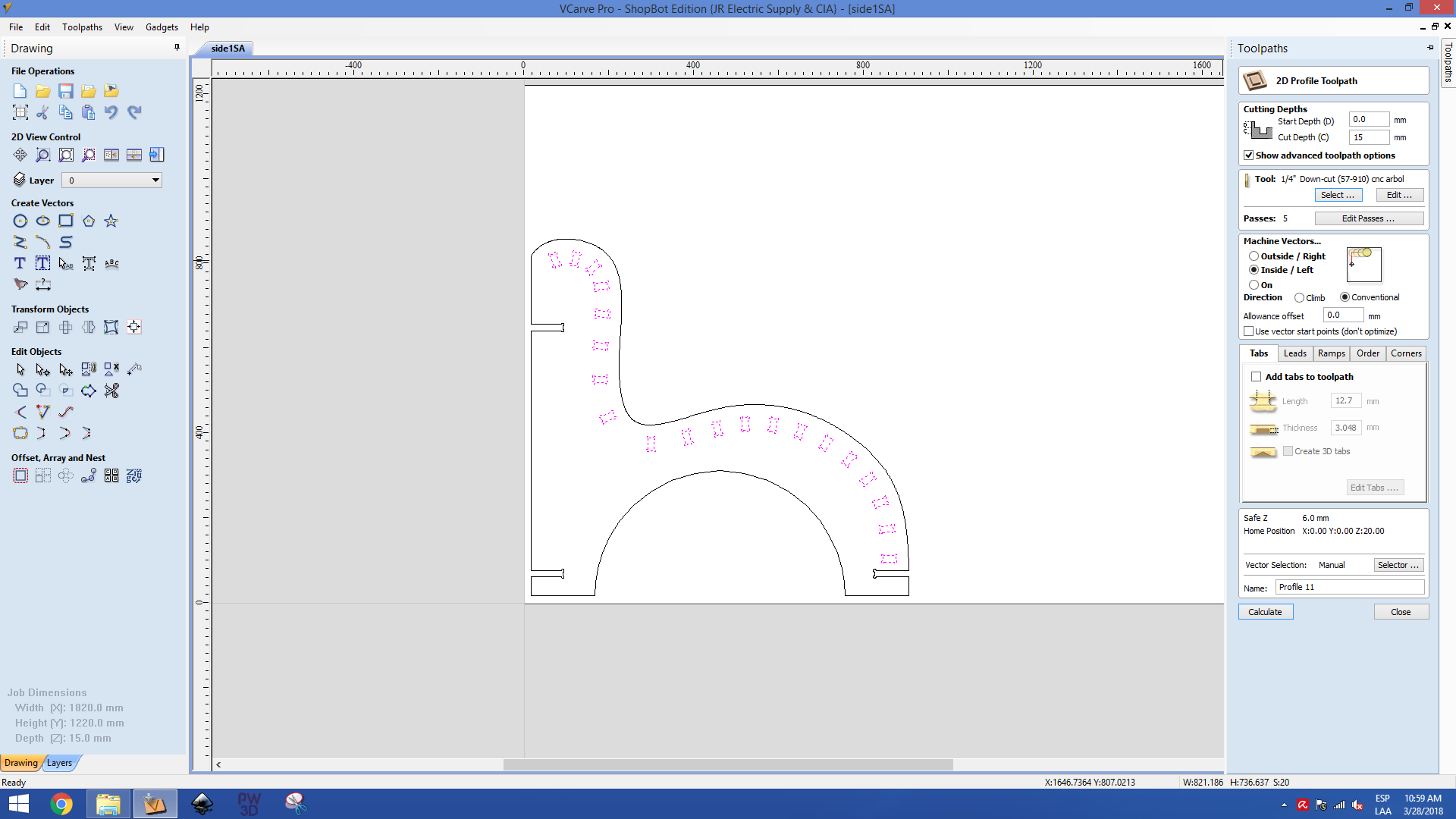
Here is the tool ready to cut.
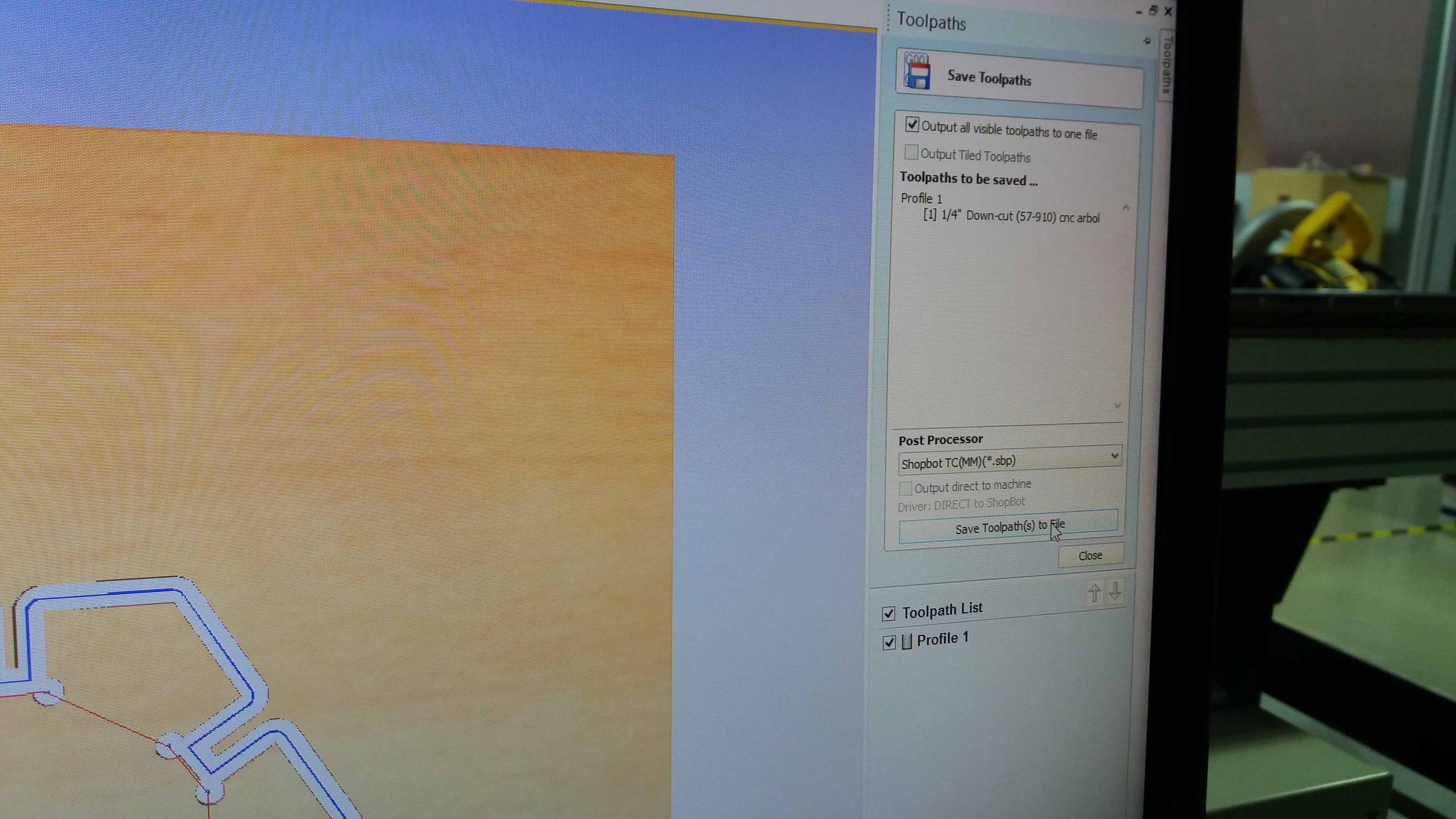
We export the file as PDF, and move the file to the computer conected to the CNC machine. Then we set the x and y coordinates in the corner we choose.
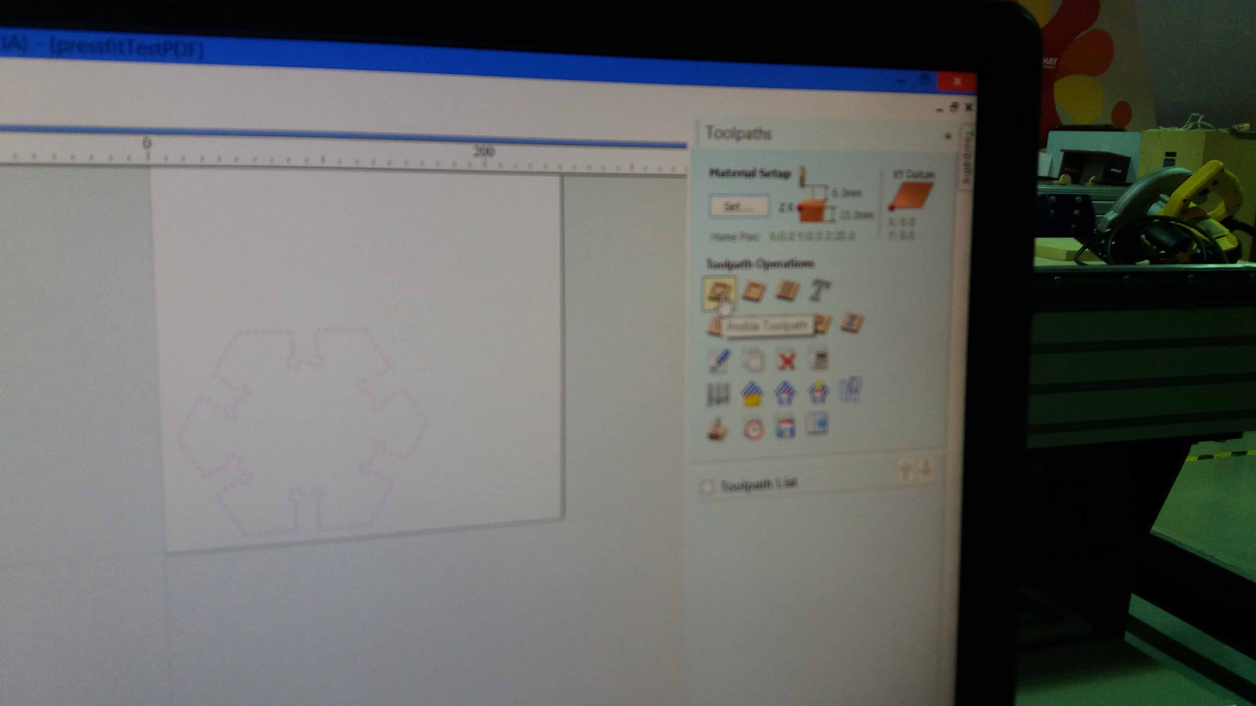
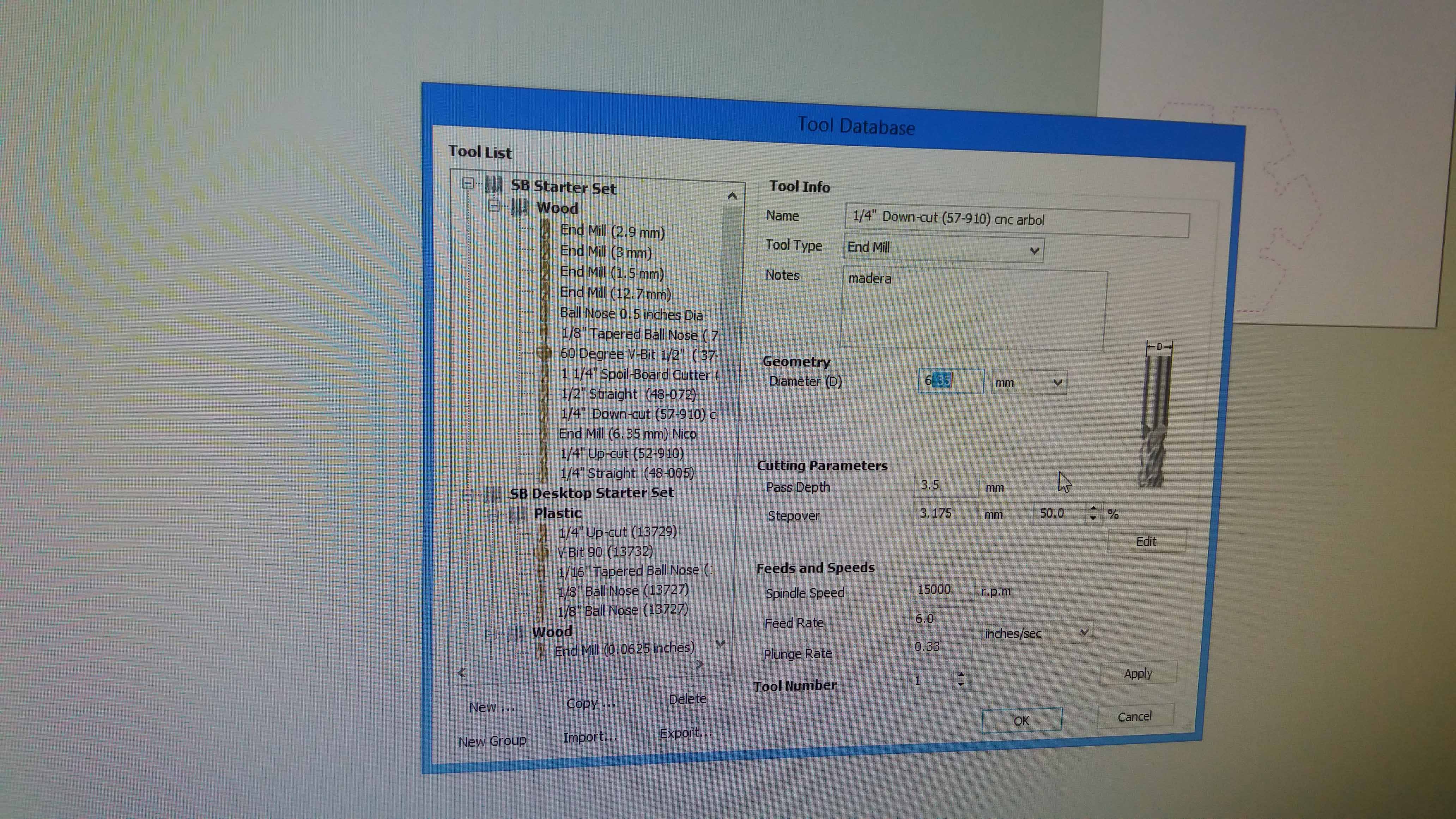
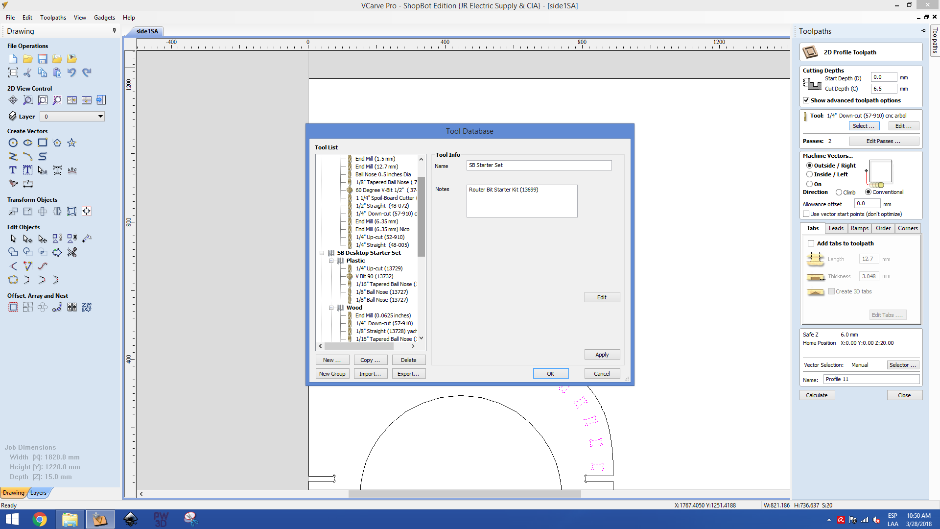
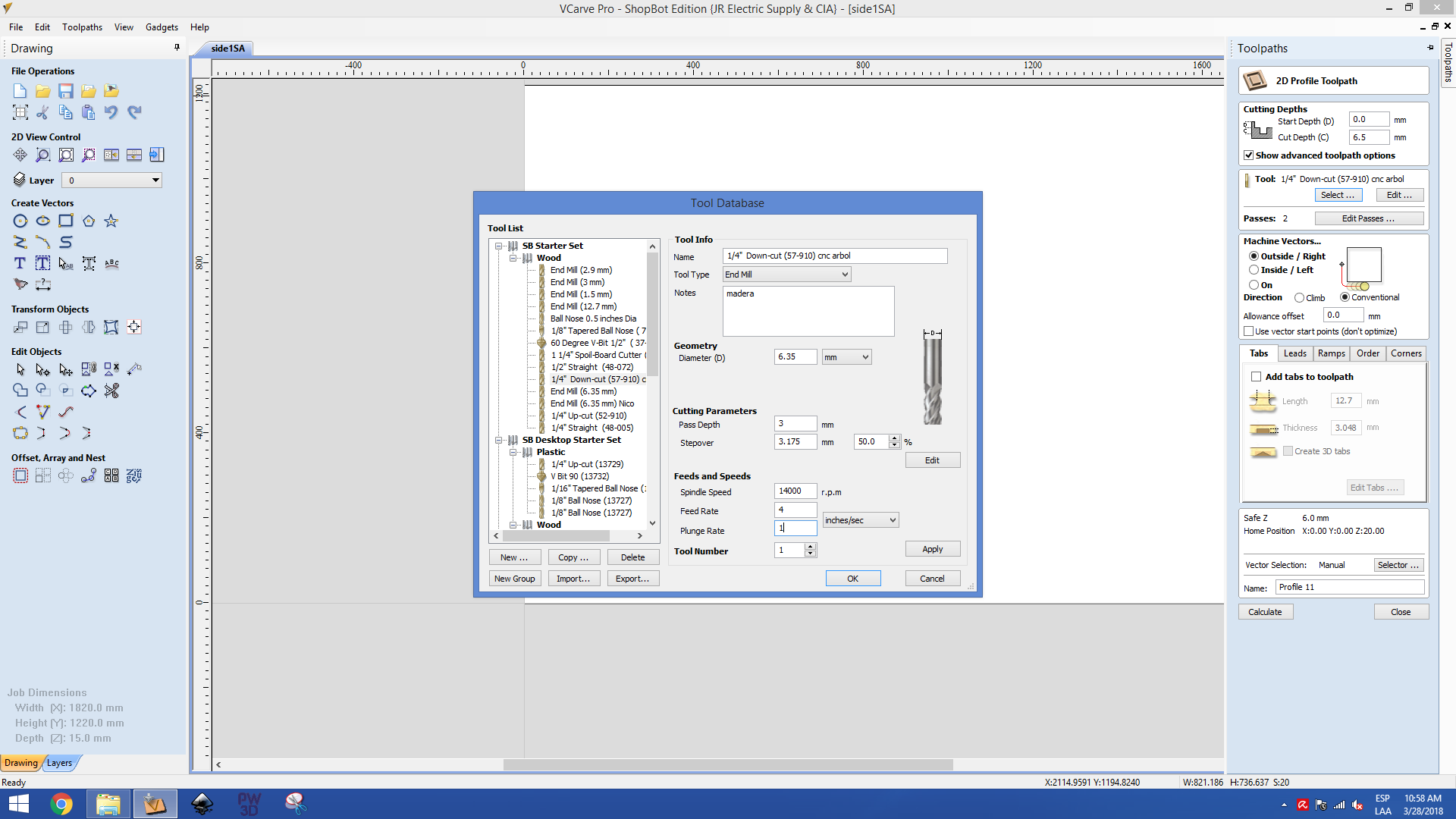
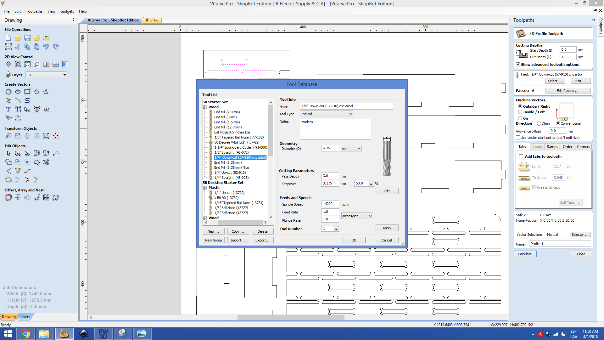
Then we choose the physical tool operating from the tools database.
Then, we position our model in the virtual cutting bed.
And run a cut simulation (with the play button).
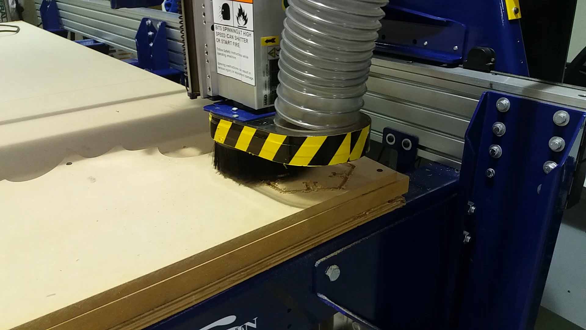
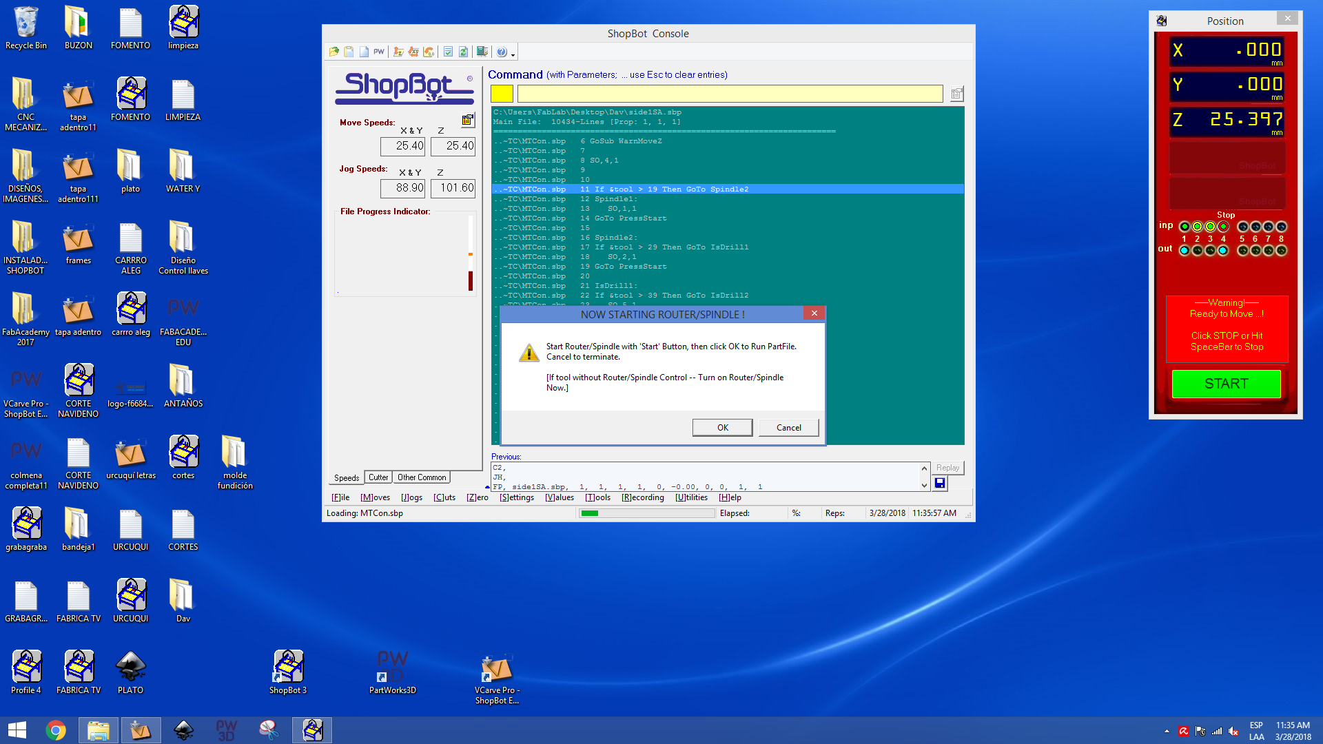
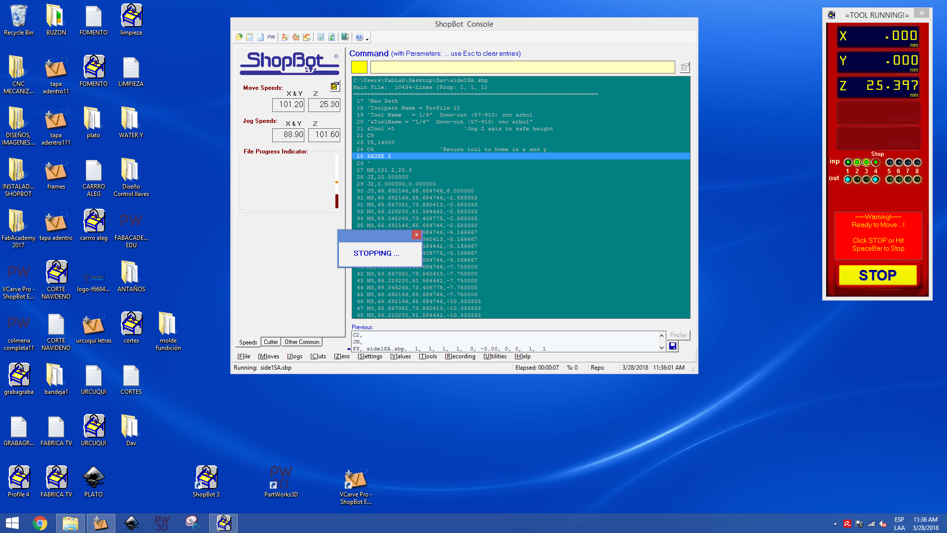
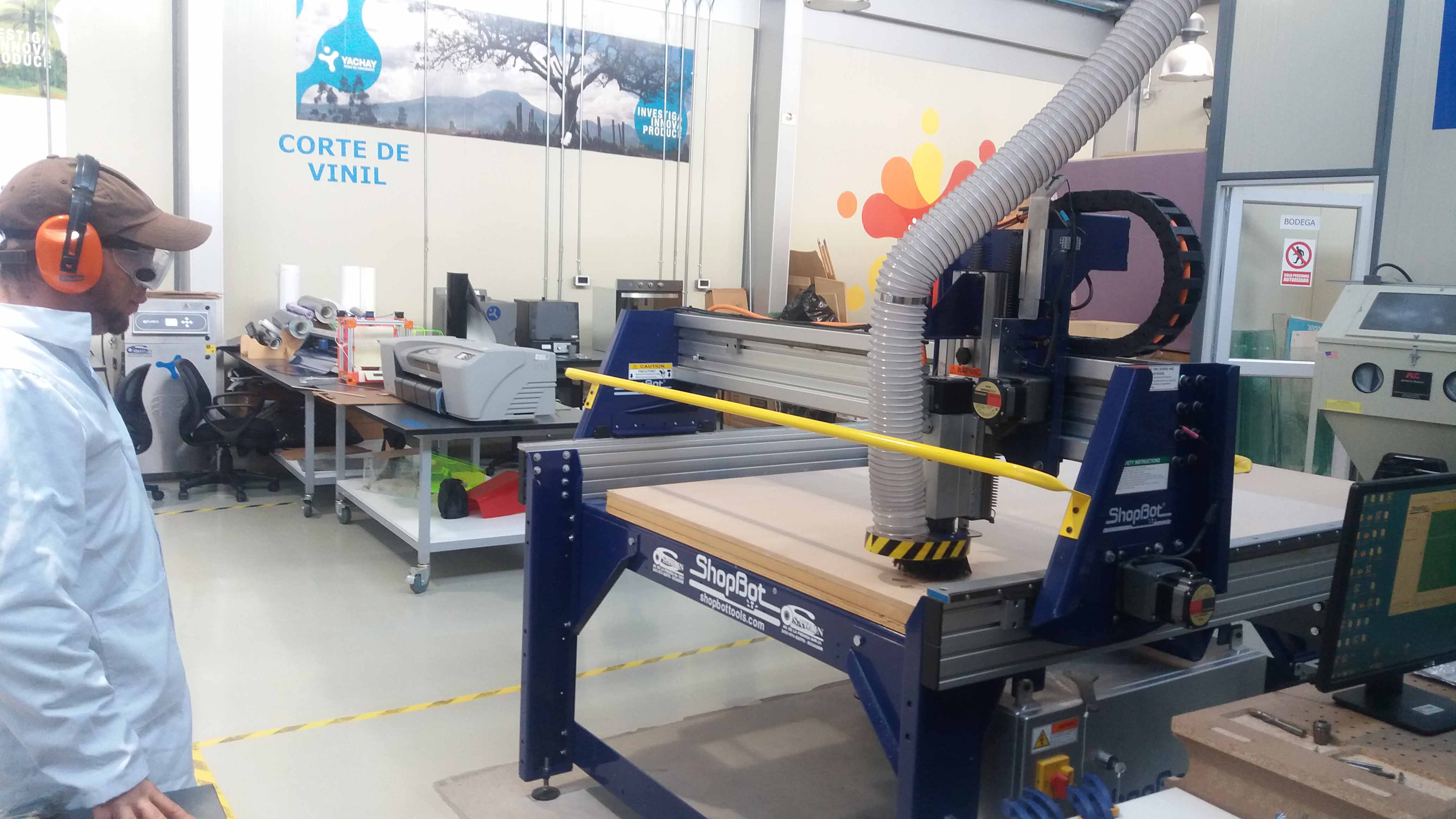
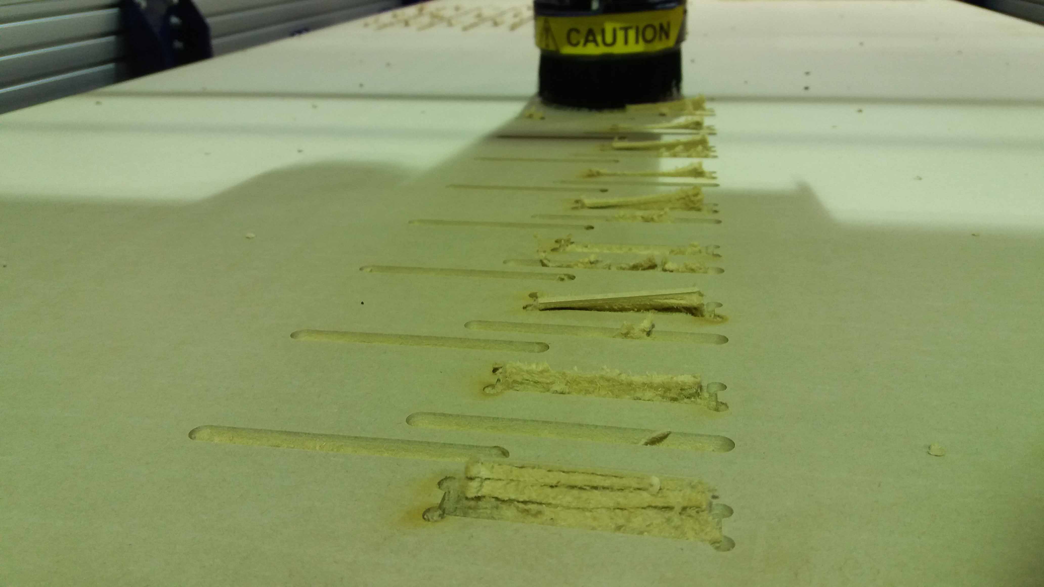
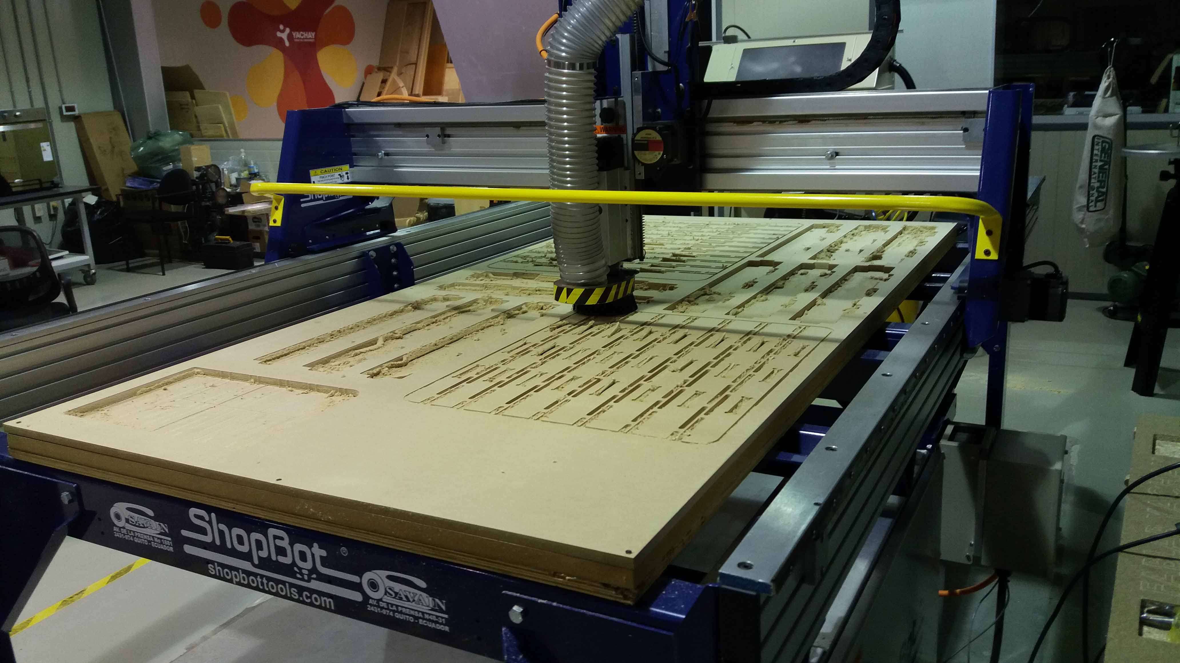
Then we start the machine and proceed with the milling.
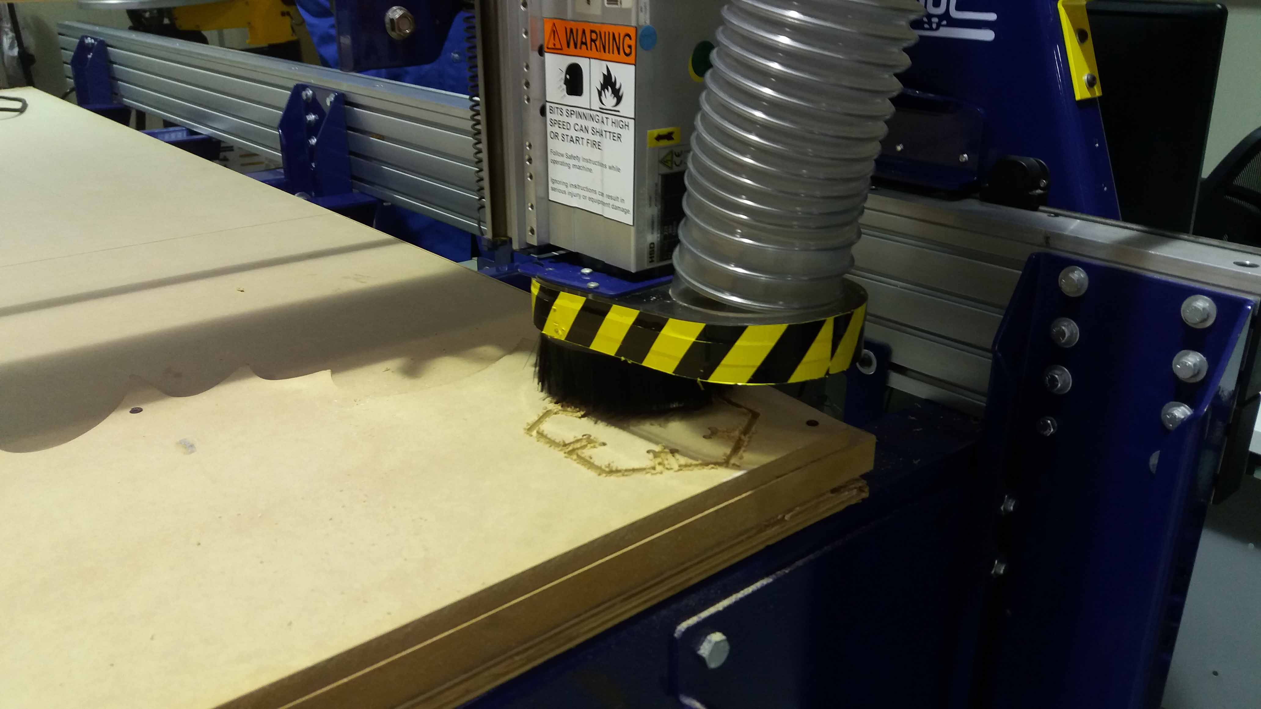
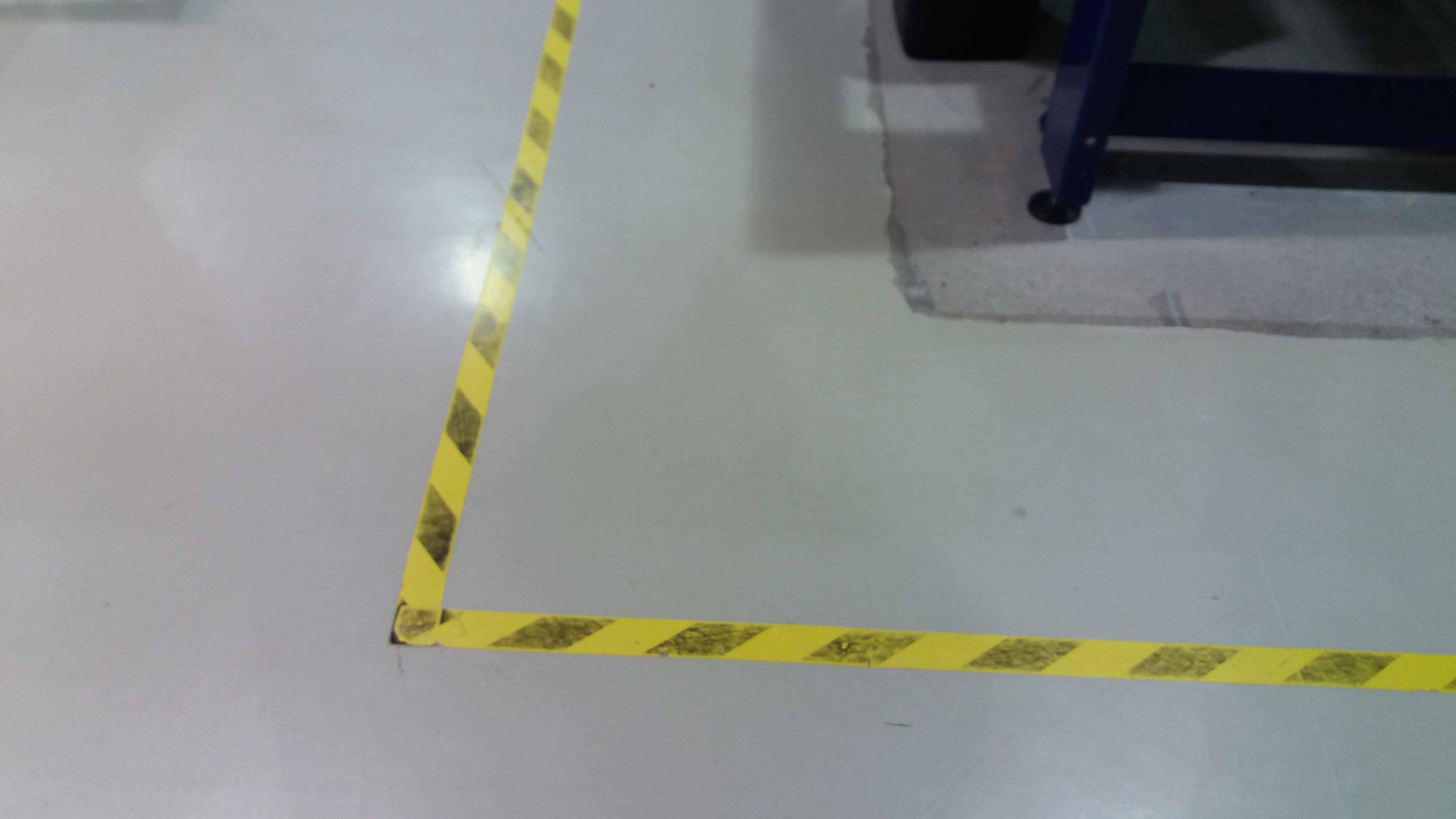
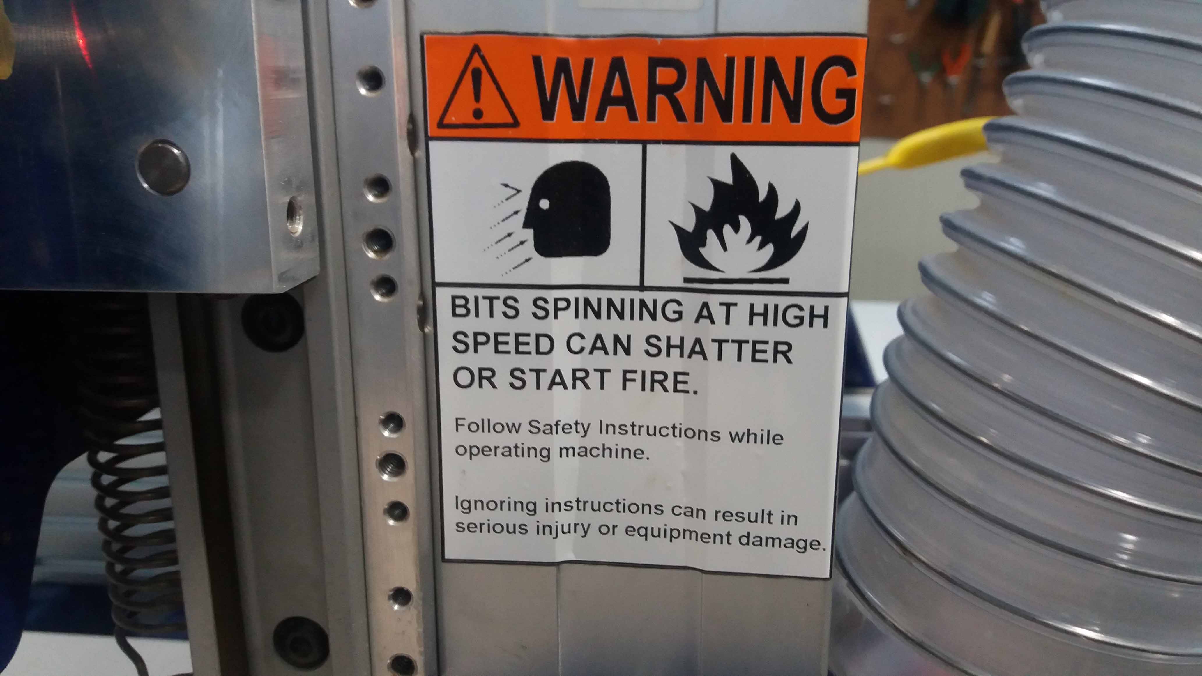
Remember to always step outside of the yellow and black line on the floor while the machine is in operation.
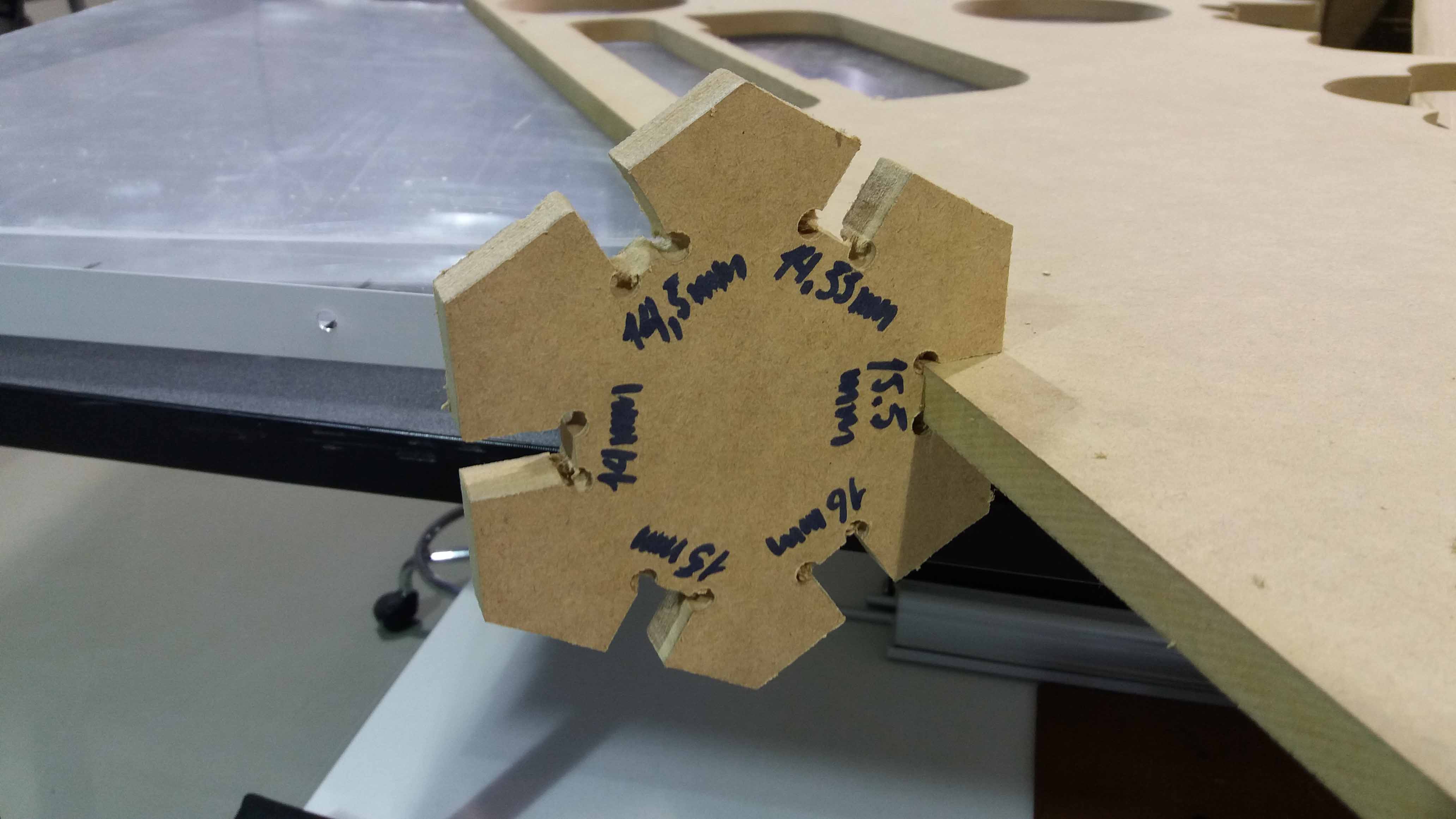
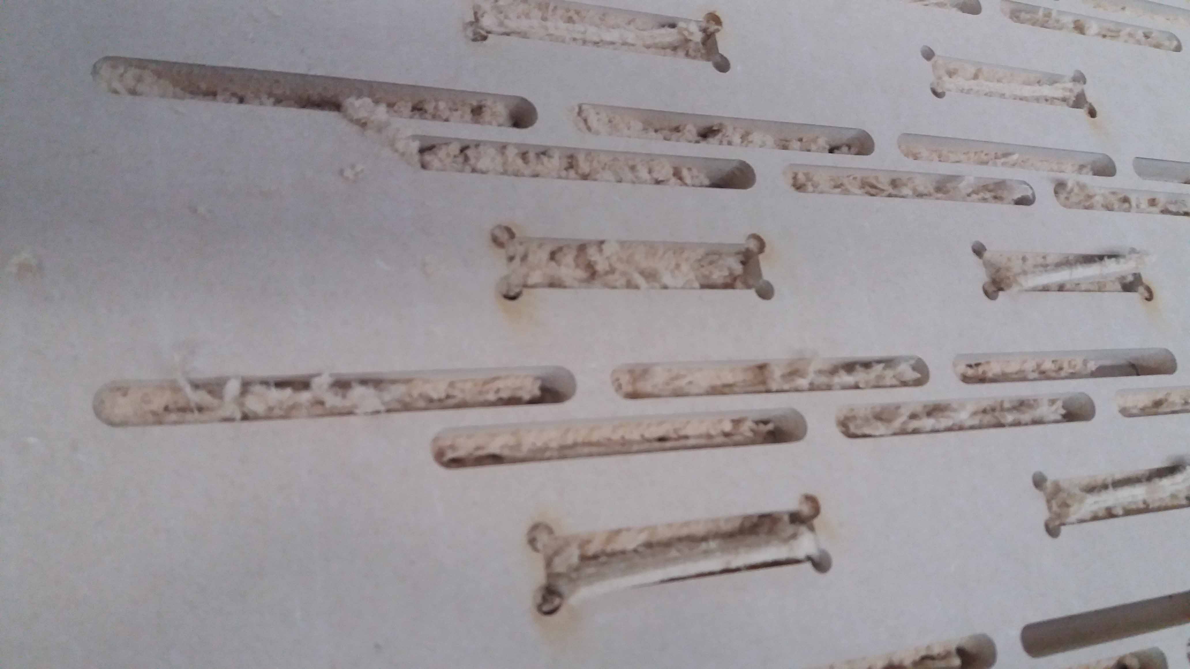
Finally, the machine finishes the job...
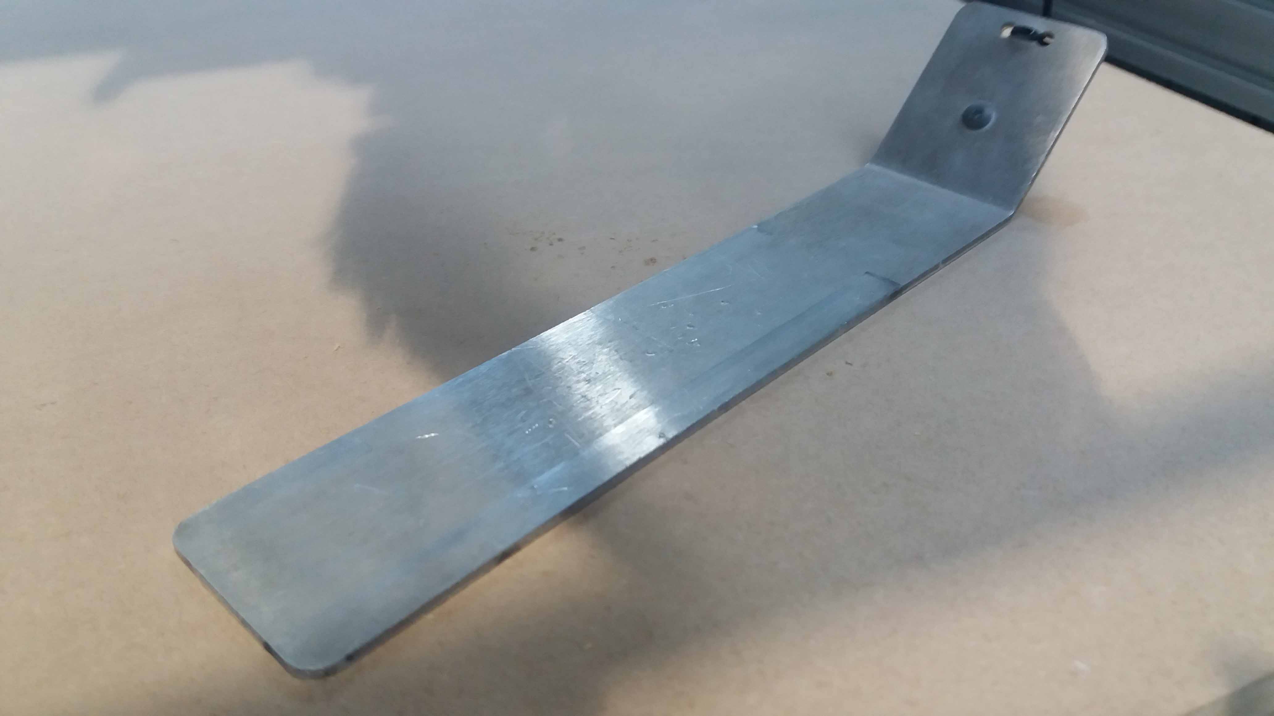
And we have the tool that alow us to determine the tolerance needed for a perfect fit.
The files used in this exercise can be downloaded from this links:
Press fit tolerance determination tool,
Press fit tolerance determination tool 1,
Press fit tolerance determination PDF.
Furniture design
Then, we use this information to desing something big to be milled in the CNC machine.
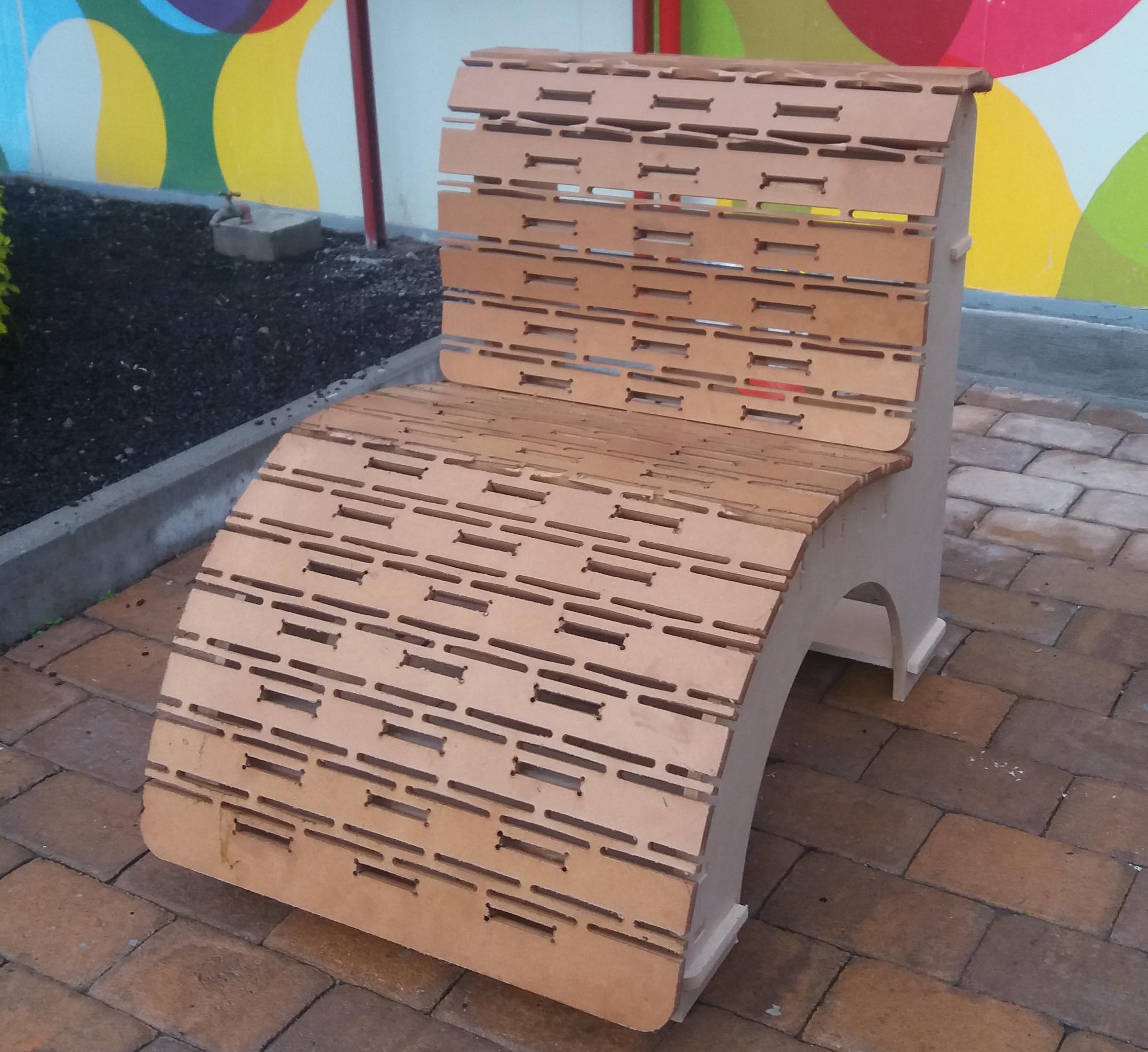
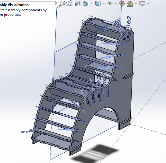
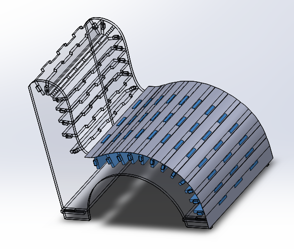
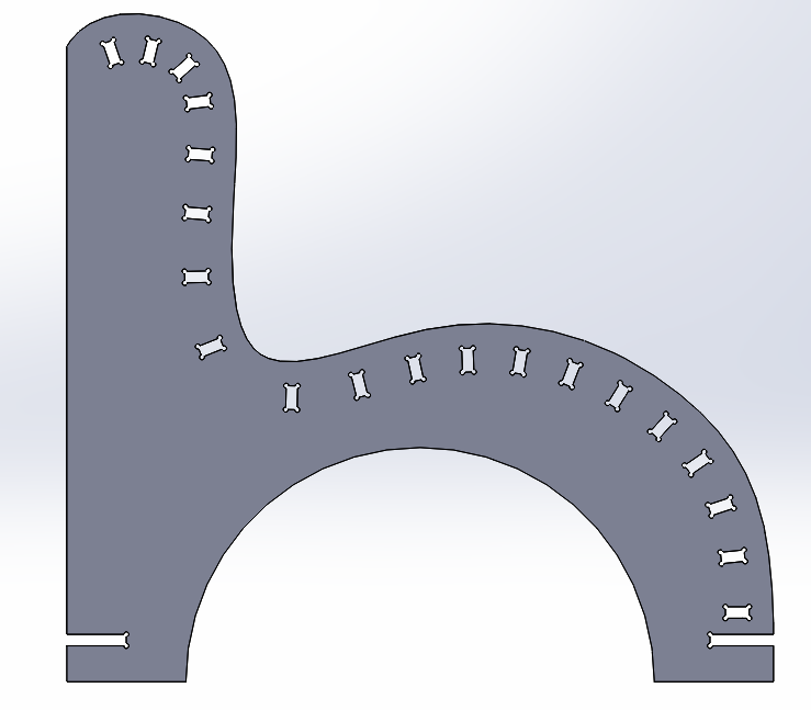
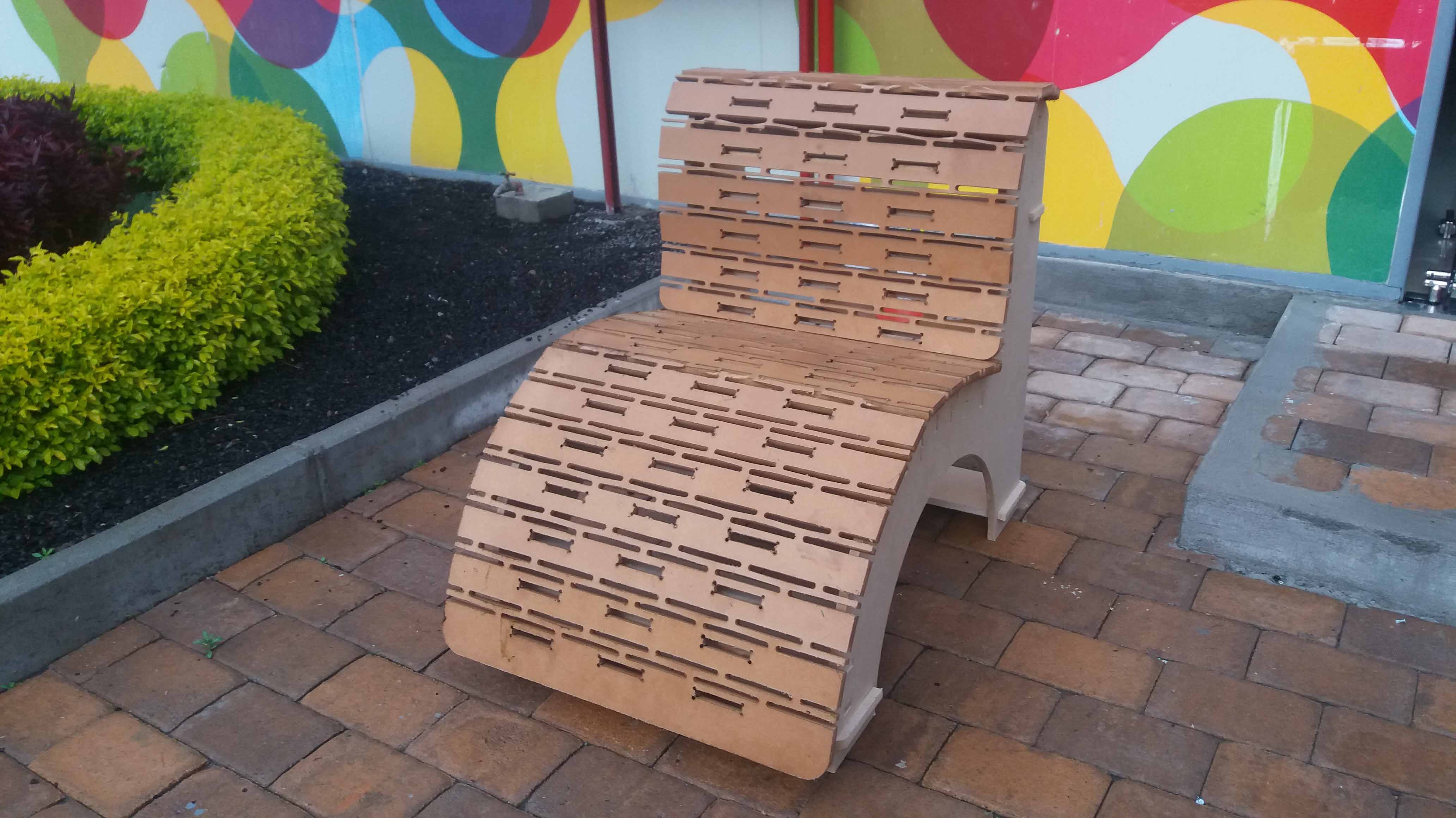
I decided to work over a chair design I found interesting, using living hinges. Maybe it was a little risky, but I wanted to experiment with the technique. I added ribs to the "traditional" design, for strength.
I started with a sketch with straight lines, a simple arc and a spline. Then I created the pieces for future intersection, and used a pattern for the ribs using the spline as a refference. Then, inside the assembly I used the command "insert/cavity" for creating the holes in the side pieces, using an top-down design aproach, as done in Computer Aided Design class.
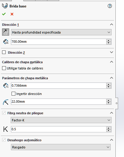
Then I run into trouble. For the creation of the covers, I though using the spline for sheet metal generation would be the next step. Unfortunatelly, Solidworks sheet metal is not compatible with this kind of geometry. I had to create my own path composed of straight lines conected with splines.
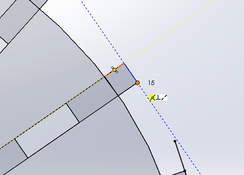
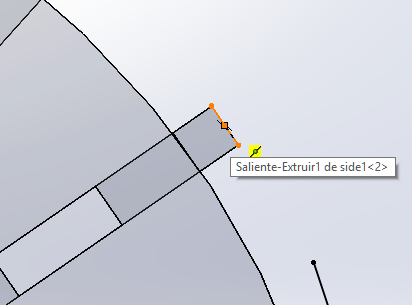
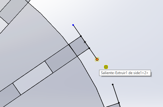
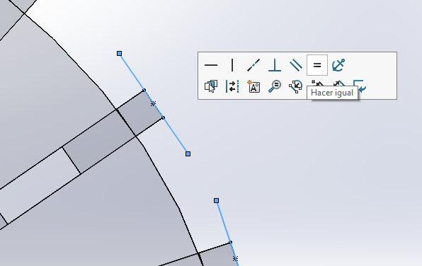
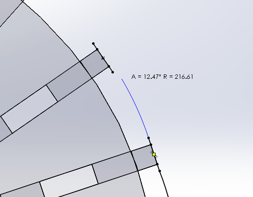
In a new part from assemby, I used the top of the upper part of the ribs to create a construction center line to define the center and angle. Then, using the center as a refference I drew a line with the length of the part of the cover that will be not bended. Then, I defined lenght and/or relationships ("equal", for most of them).
Then, I joined two of them with a spline.
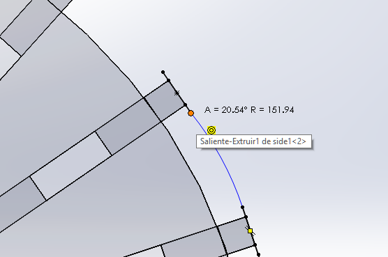
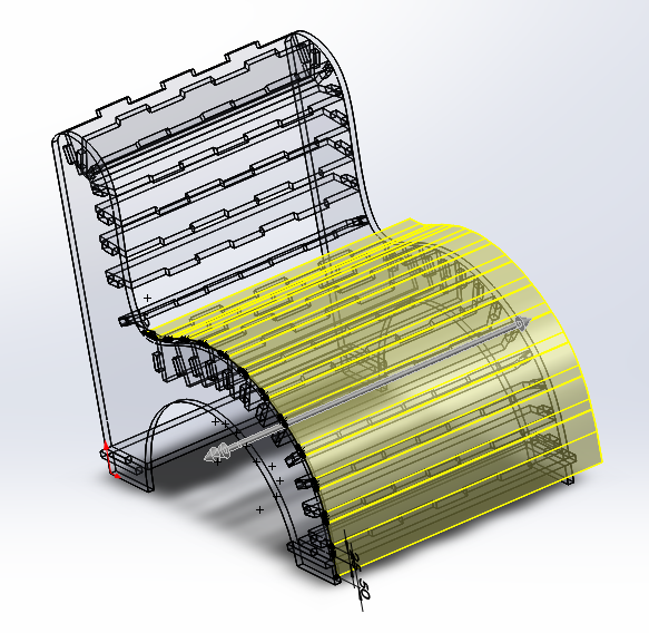
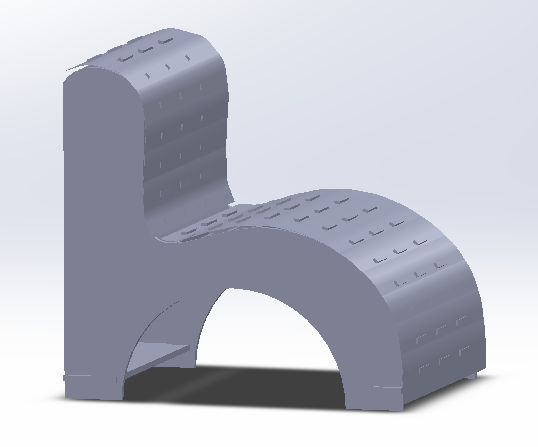
The result worked for a sheet metal part generation.
Then we use mates to locate the parts in position and proceed with the "insert-cavity" operation in order to get our pockets (holes).
We choose the parts from the design tree, so we make the cavities in a single operation.
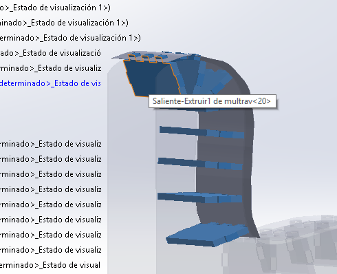
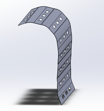
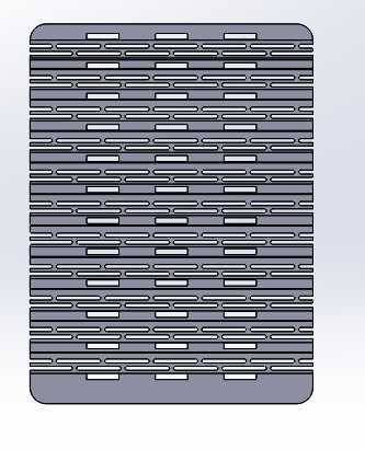
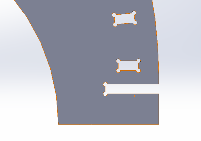
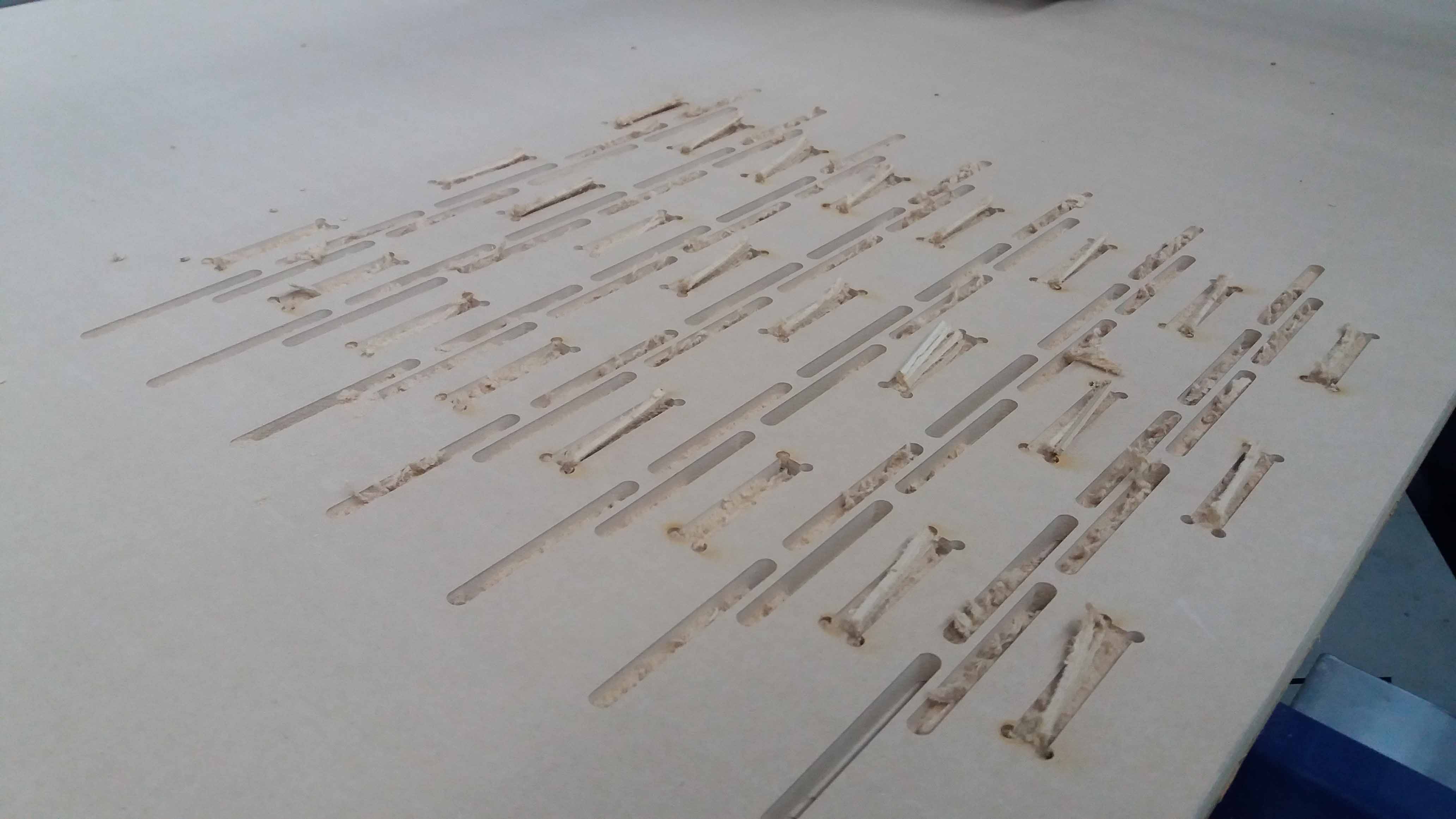
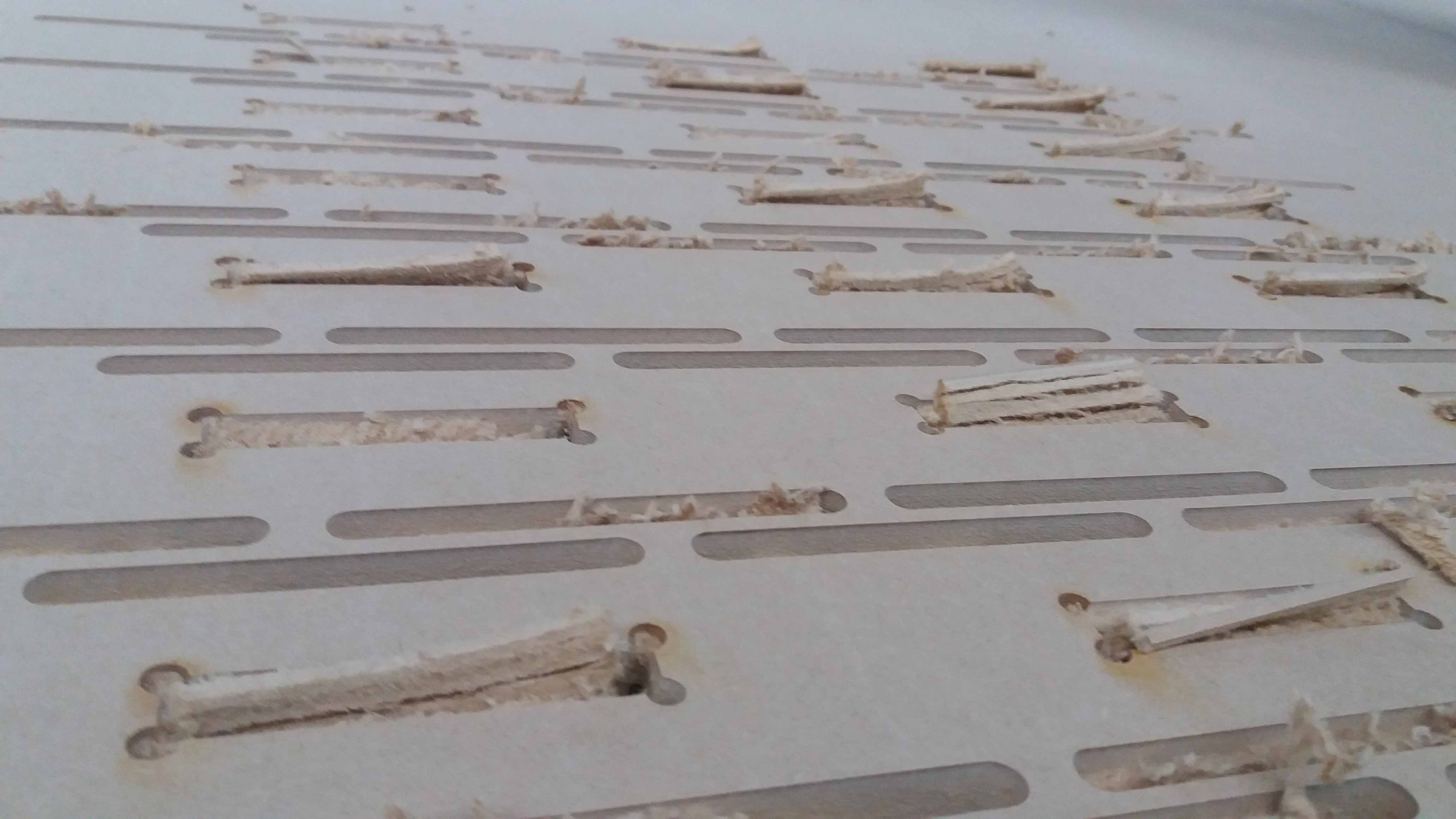
Then we proceed to unfold the result (working in "part" mode), and create the pattern of holes for the living hinge (folding) segments of the parts.
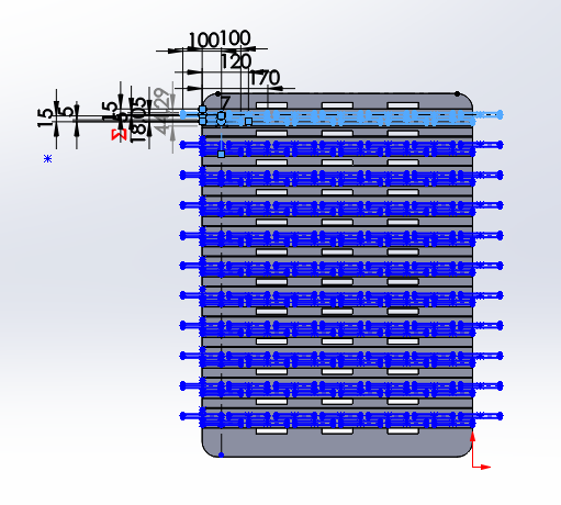
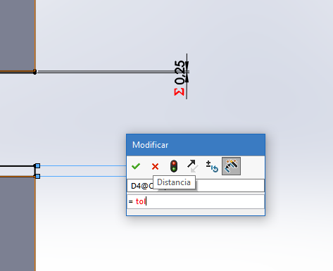
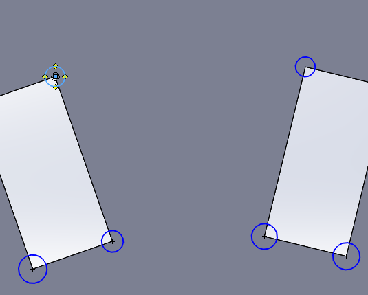
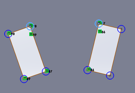
Then, we work on the individual parts to create the tolerance it needs to make a solid preasure joint.
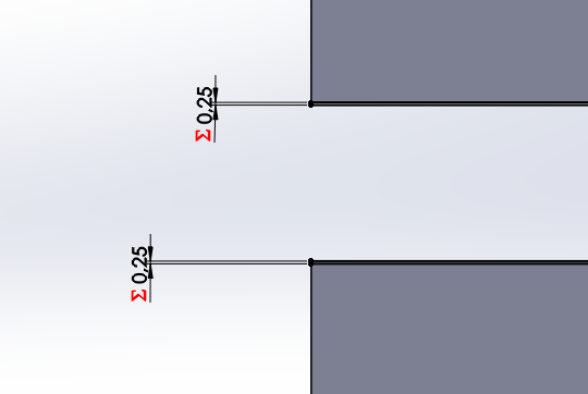
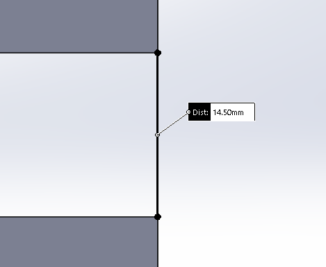
And we check it with the measure tool (just to be sure).
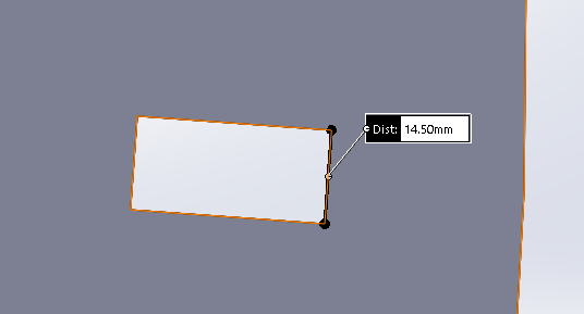
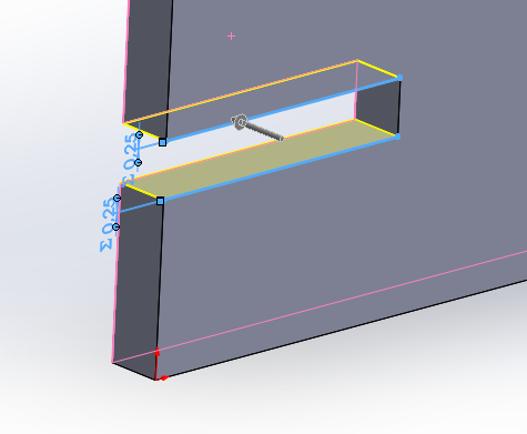
Next, we create the "ears" for preassure relief and corner reaching.
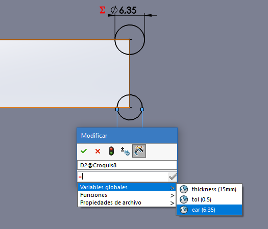
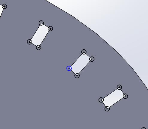
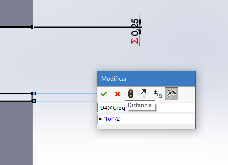
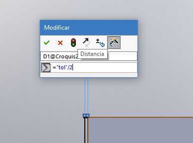
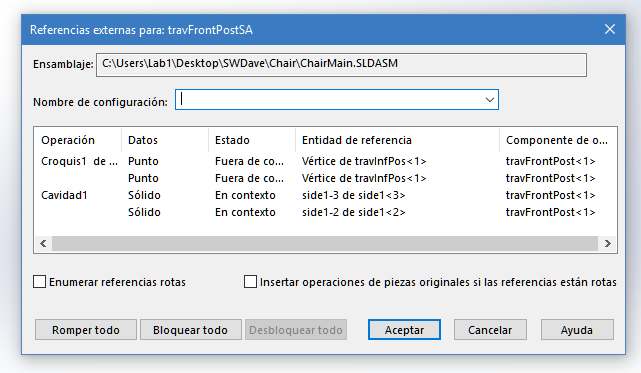
We can use math to reffer our global variables. Here I use the division by 2 of the "tol" (tolerance) global parameter previouslly defined. Optionally, we can breack the references of every piece before modifications for individual cutting.
Fabrication
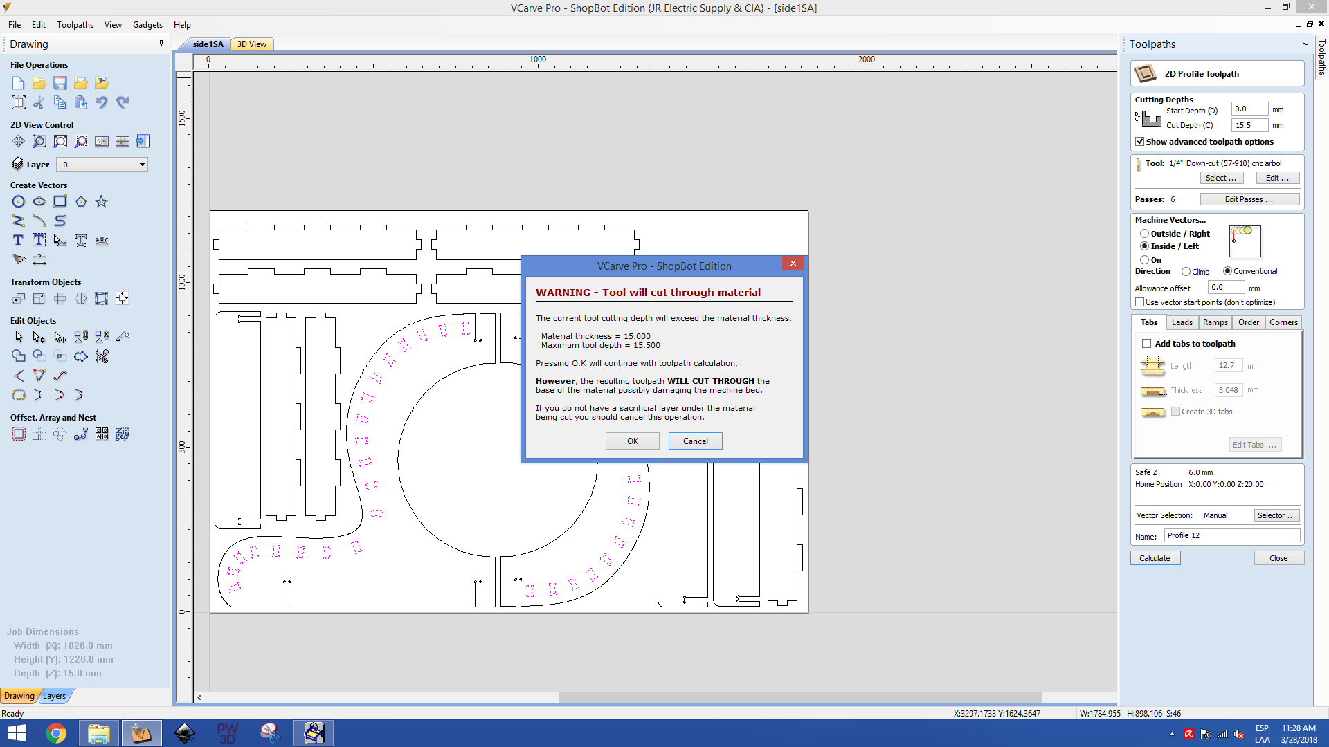
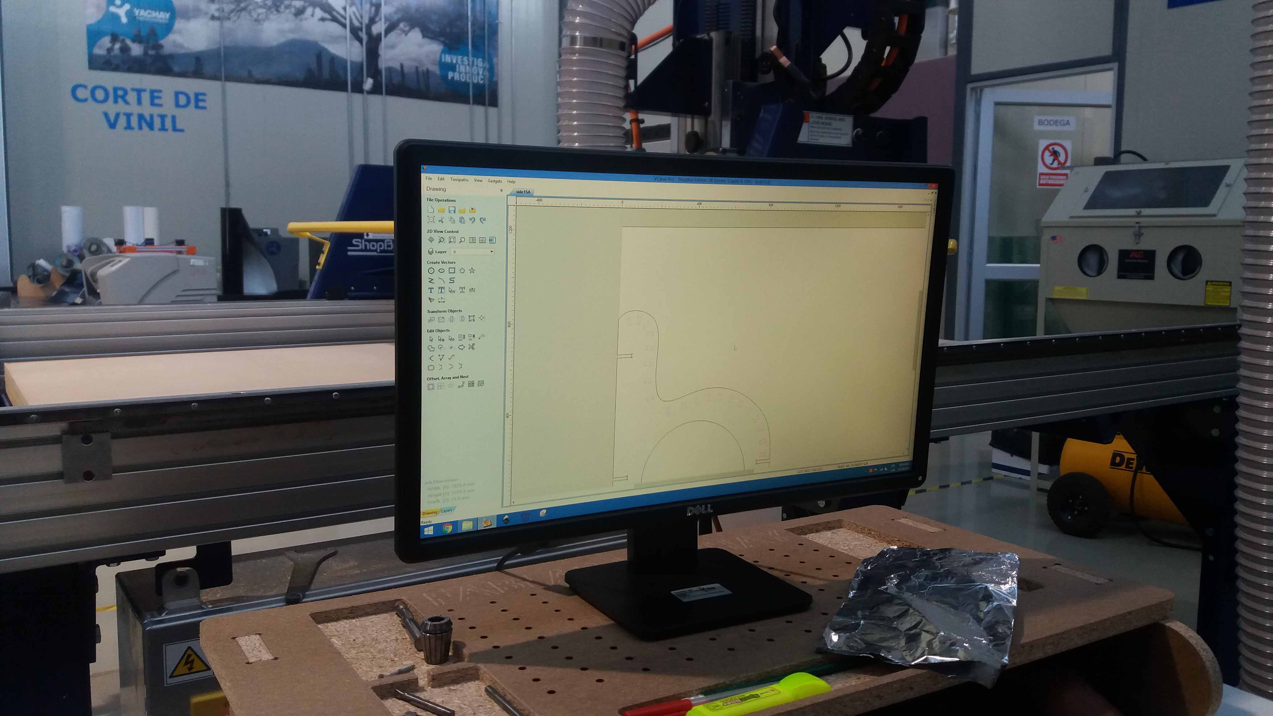
Then, we proceed to export the parts individually in DXL format. We will need them later. Before start laying down the components, we set the size of the bed and set the tool we want to use.
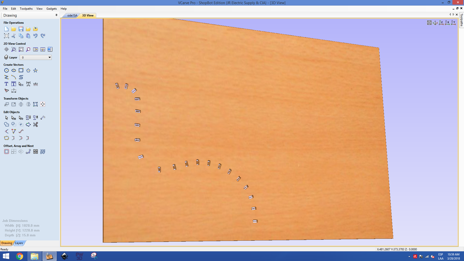
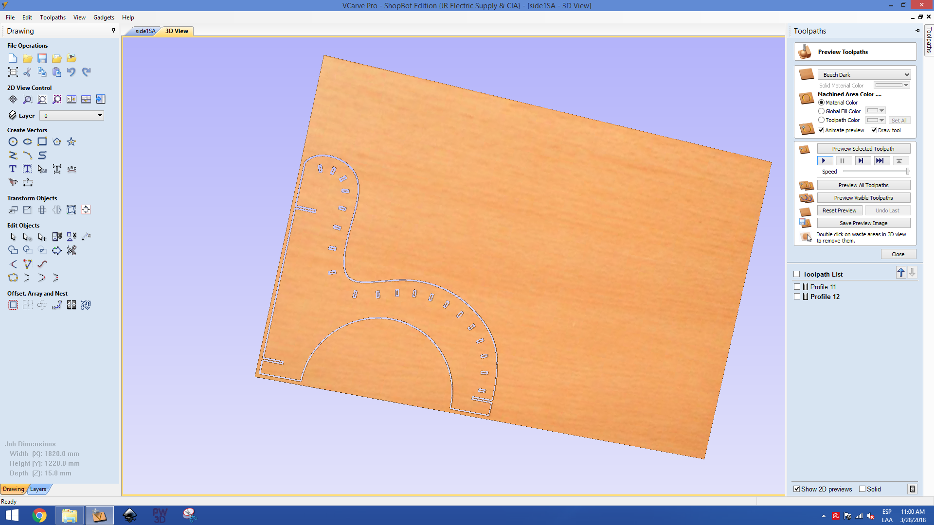
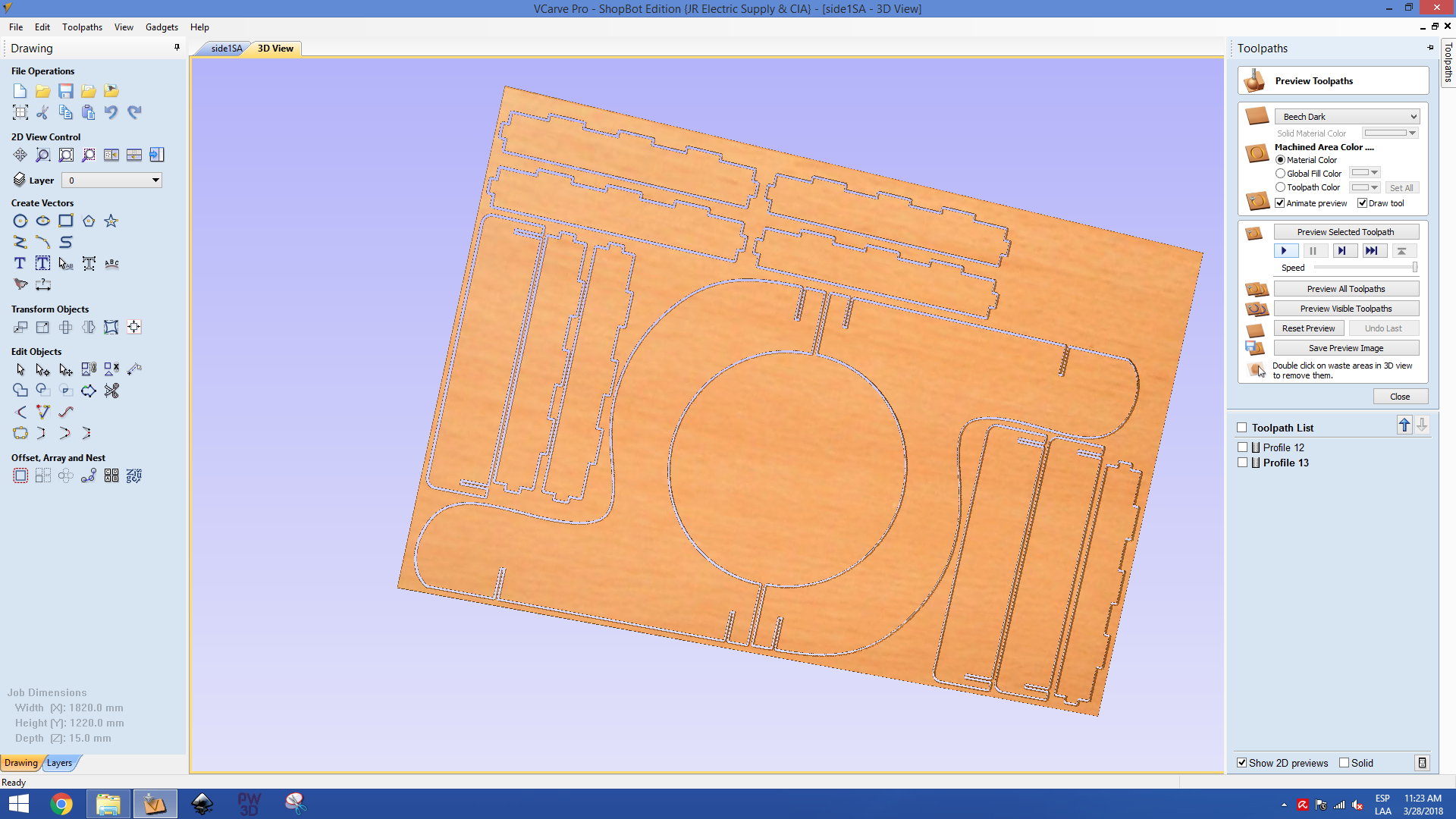
We can run a simmulation to see where the machine is going to cut
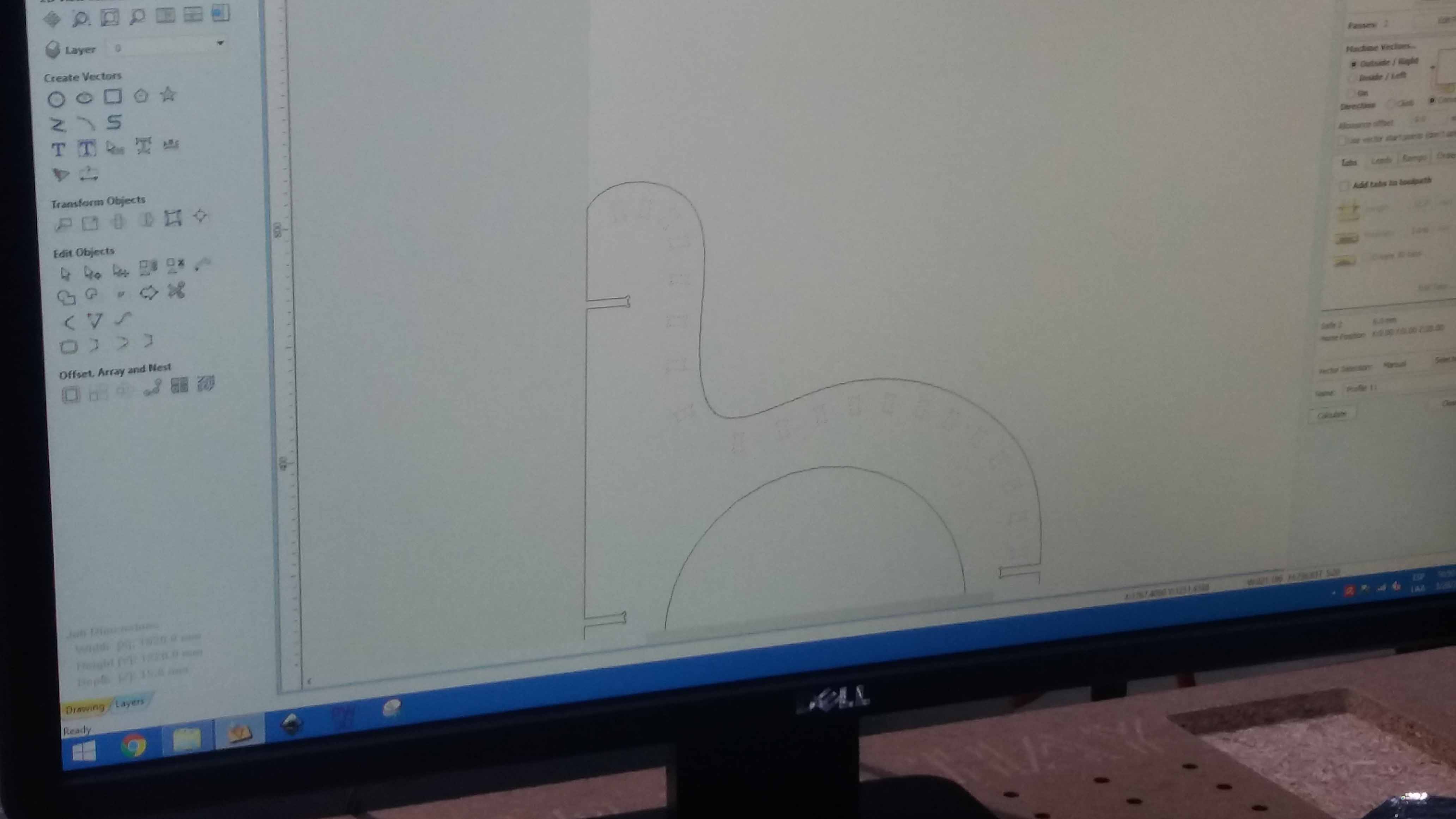
Then, we continue laying down the pieces
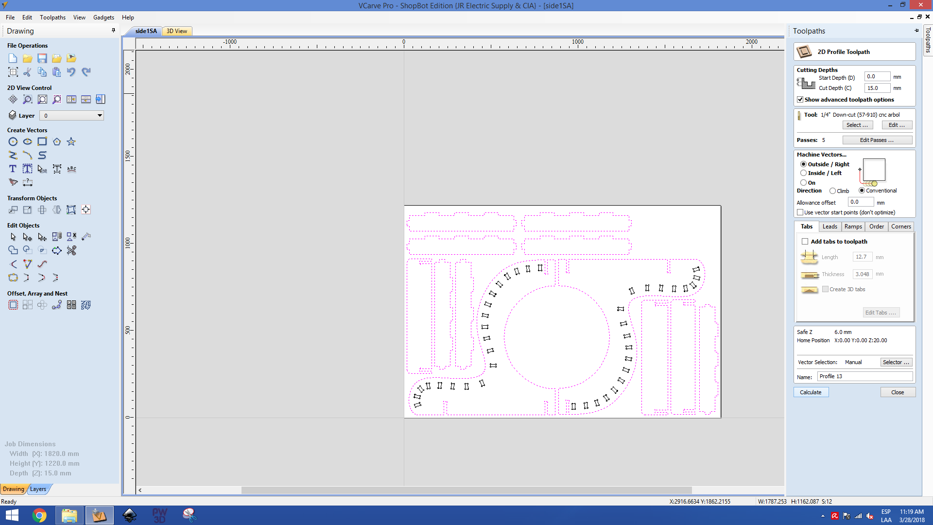
Until they all are ready and fit for an eficient use of space
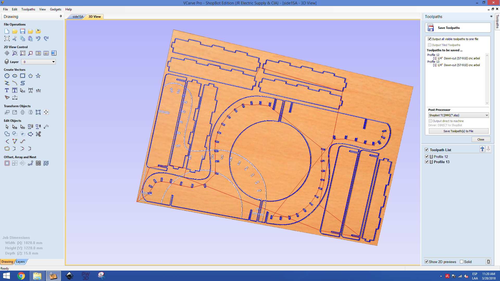
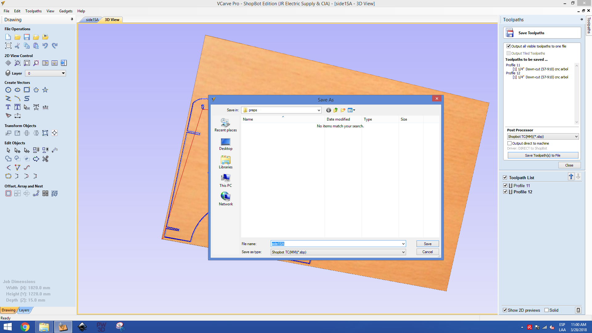
The program generates the G code necesary for the tool path guide
We set again the X and Y position for the job
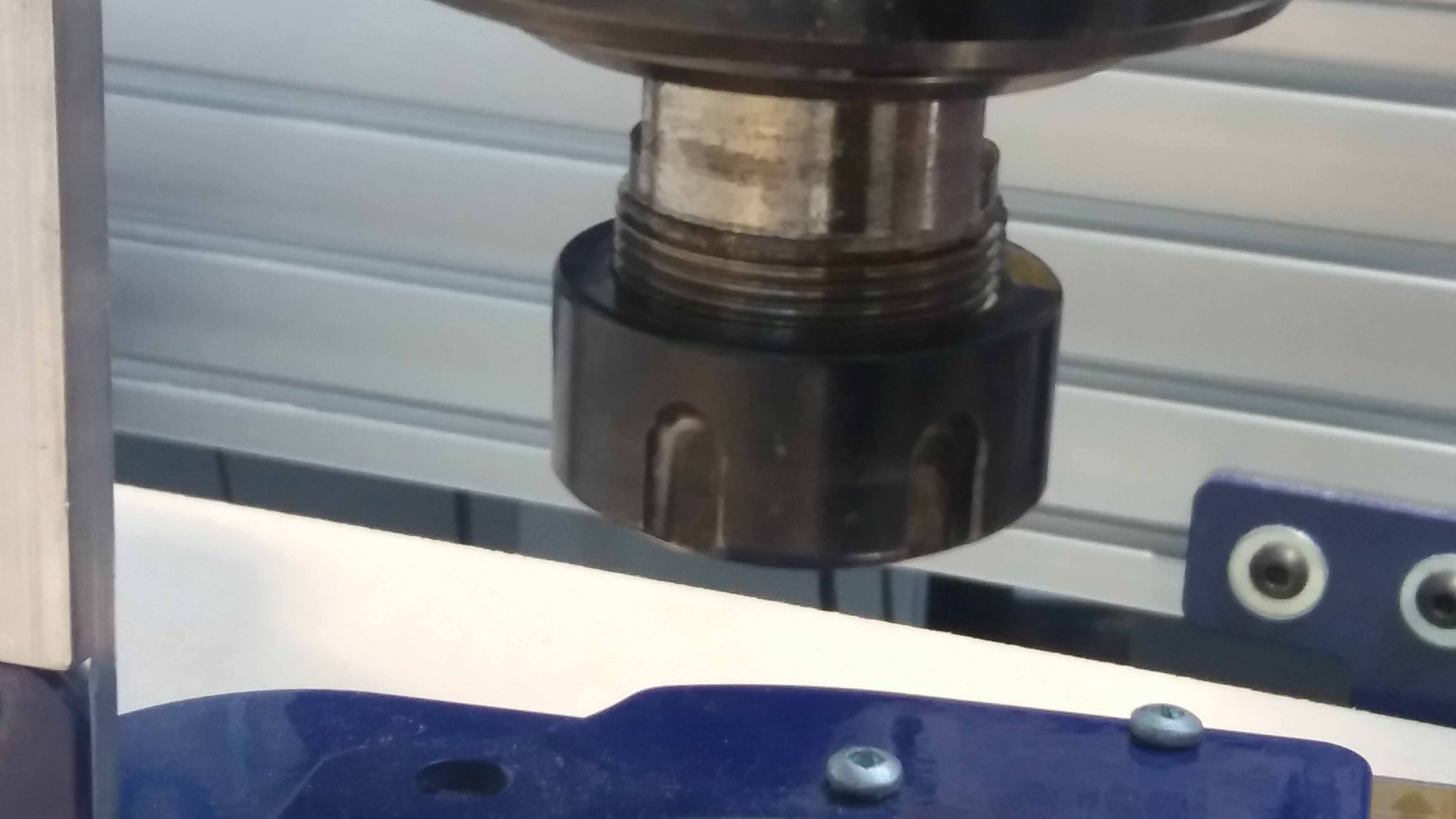
And the tool we are going to use
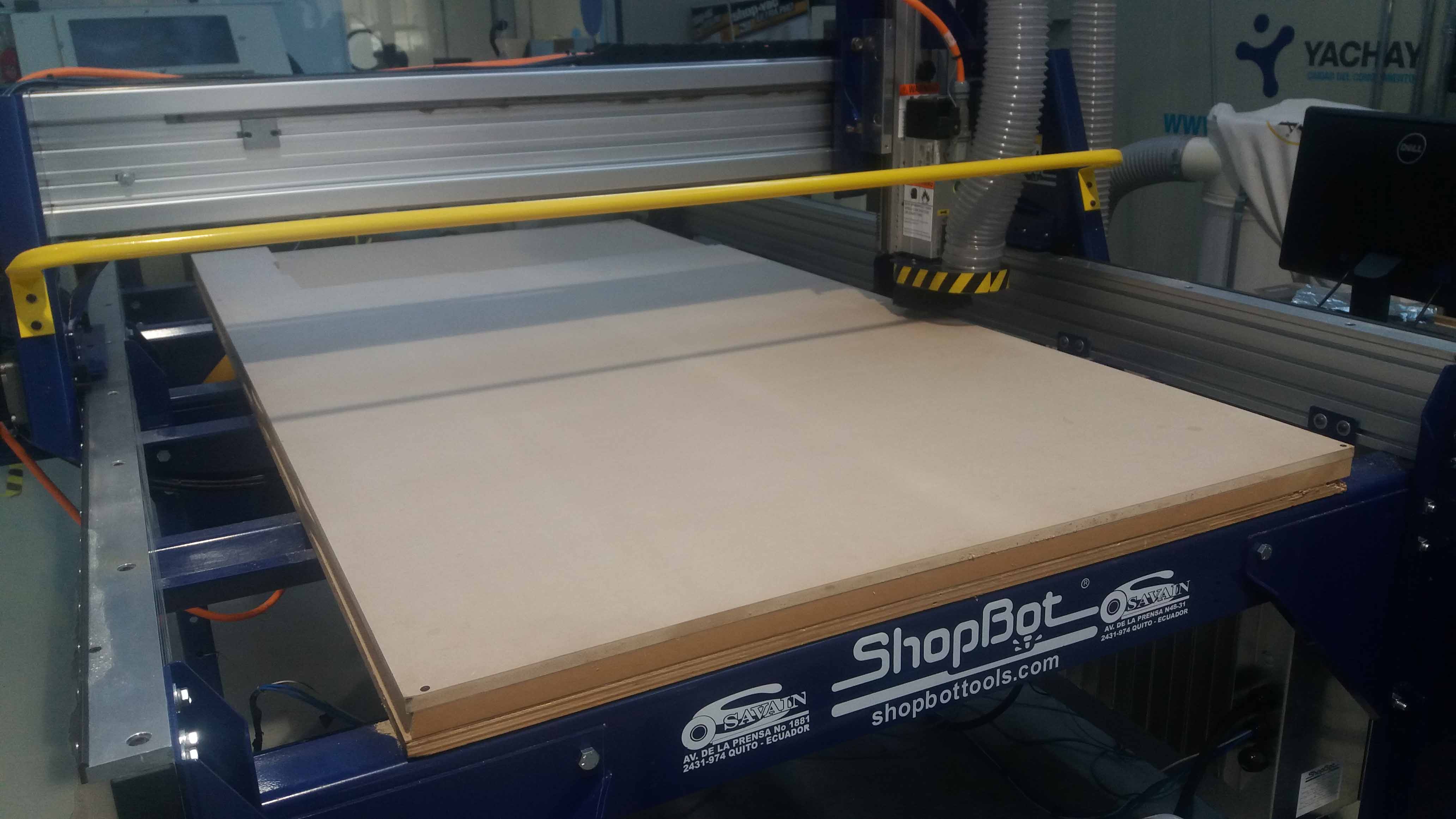
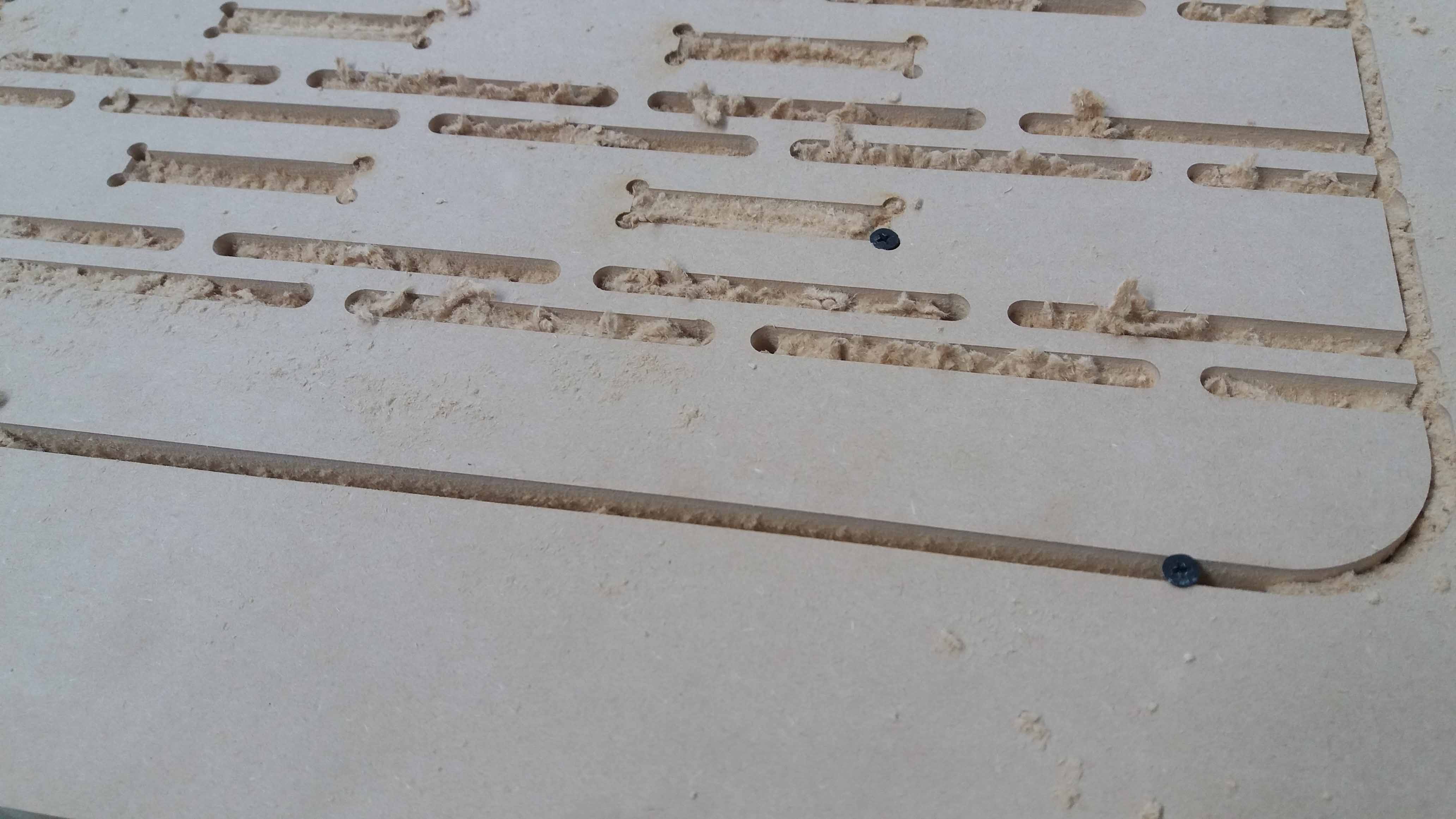
Next, we set the cutting bed and material. We use wood screws to secure the corners of the material to the sacrificial layer. Then, open the DXL files we created previouslly and lay them down in the manner they occupy most of the space, with at least 1cm of offset with respect to each other.
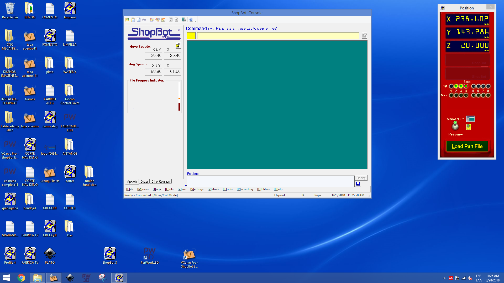
The sofware and hadware are almost set
For the z axis, we use a sensor the define the 0 position. We need to conect the sensor to ground for the test, and lay down the sensor over the material
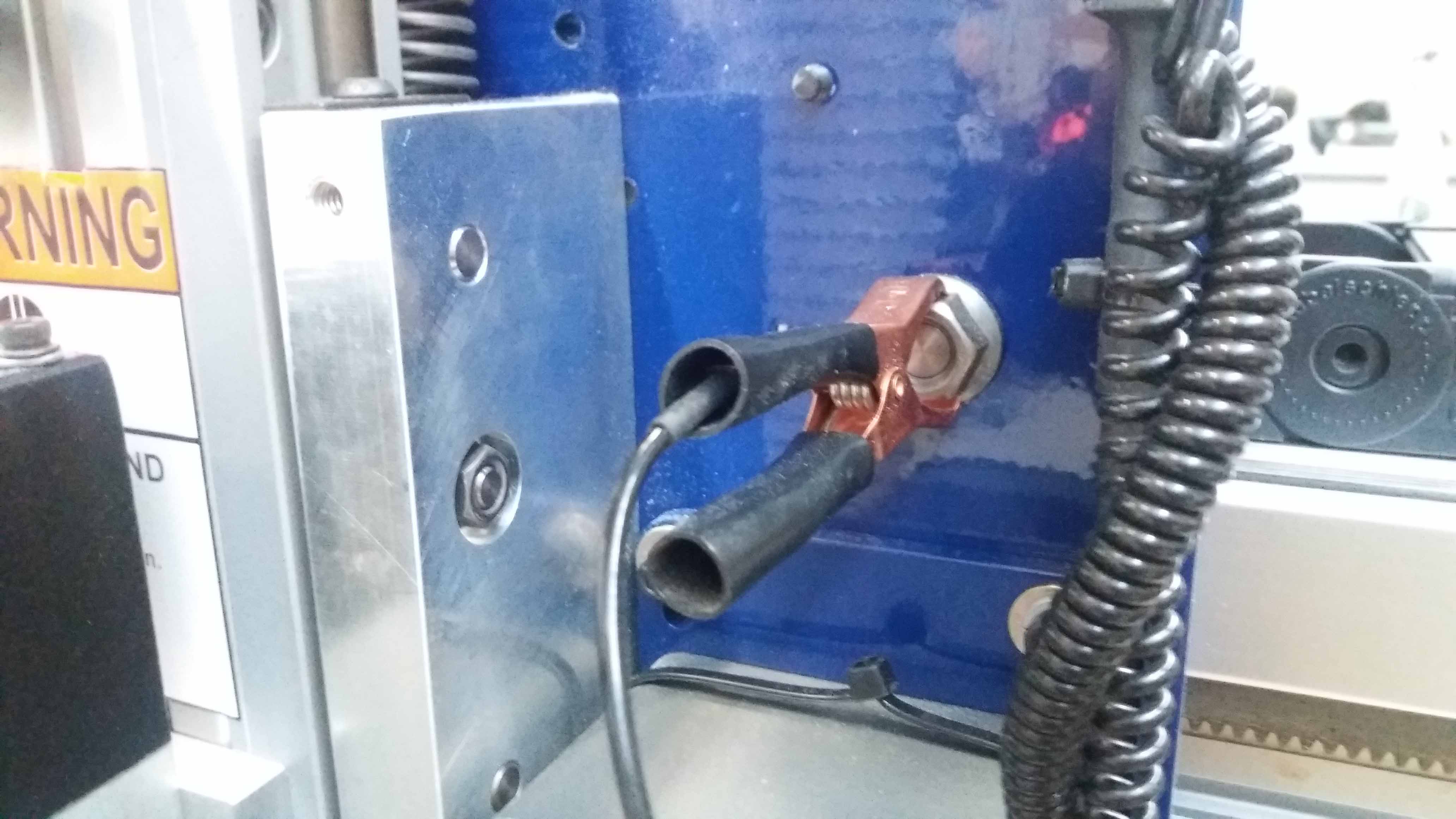
The machine is goning to move down slowly until it touches the sensor. This machine takes two measurements. The second is going to move even slower. We are almost ready, so we need to double check the security.
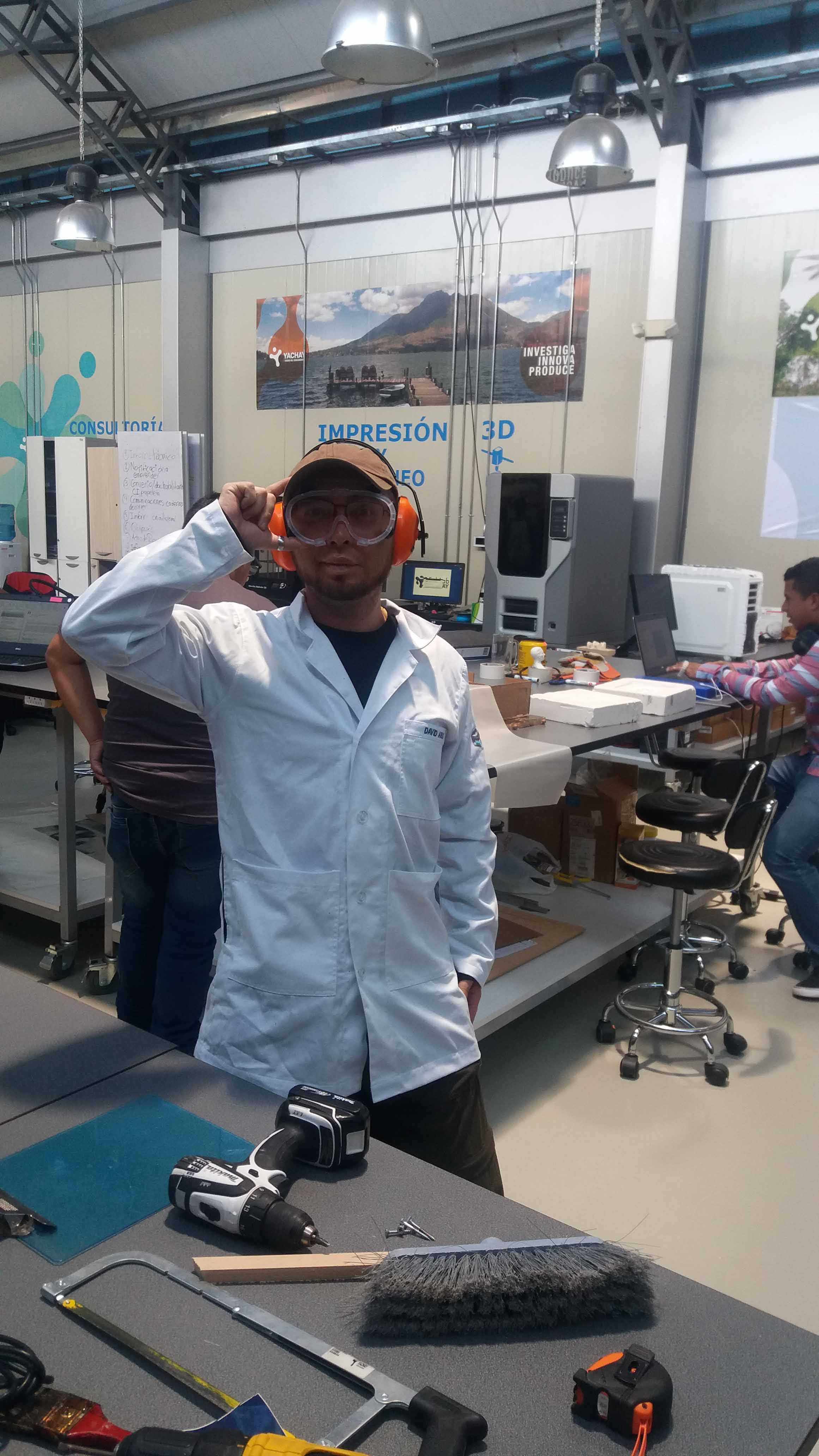
We use protection gear. Googles, apropiate wear, no gloves and hear protection are needed.
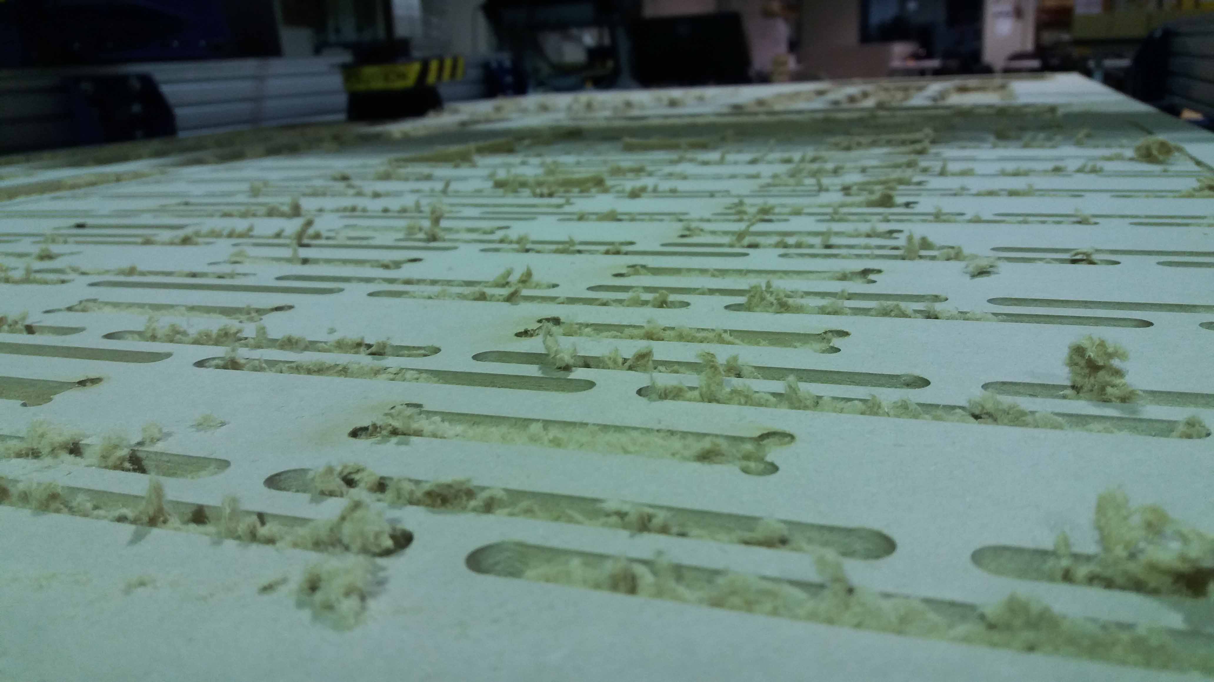
The machine starts to cut. It took quite a long time. Almost 10 hours of work. Even so, don't let the machine unatended!

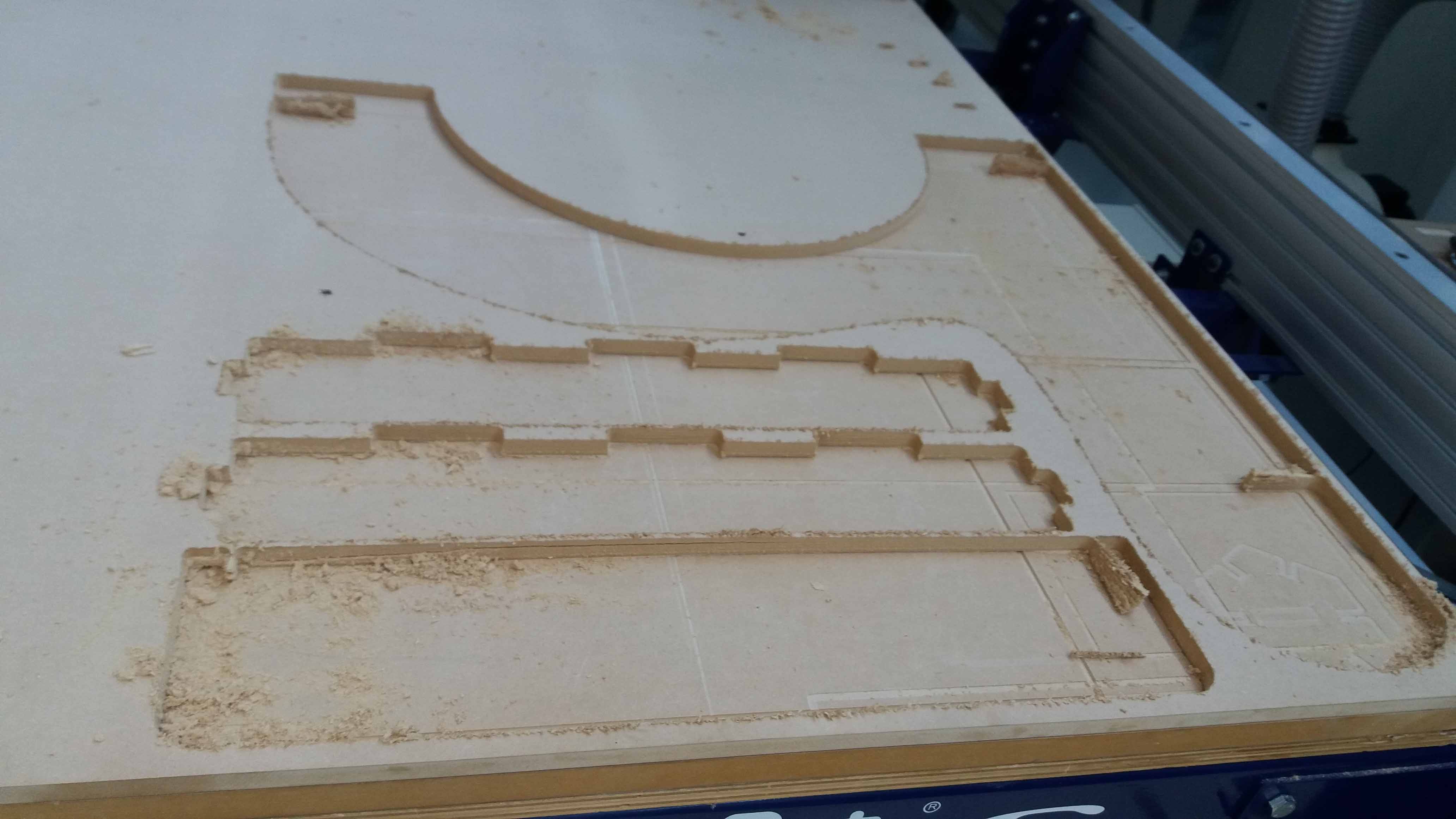
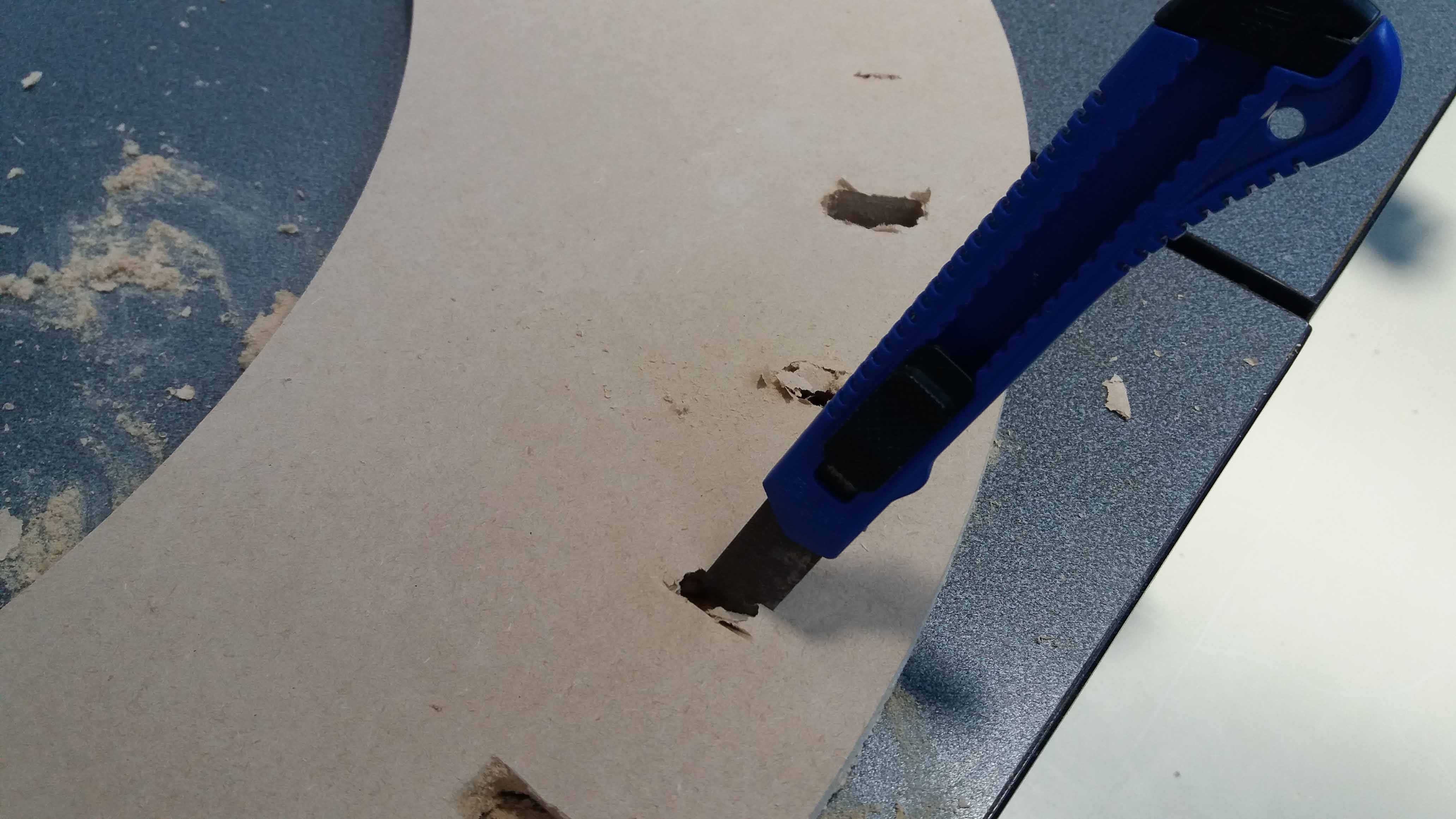
Finally, we cut manually the thin layers that wasn't entirely cut.
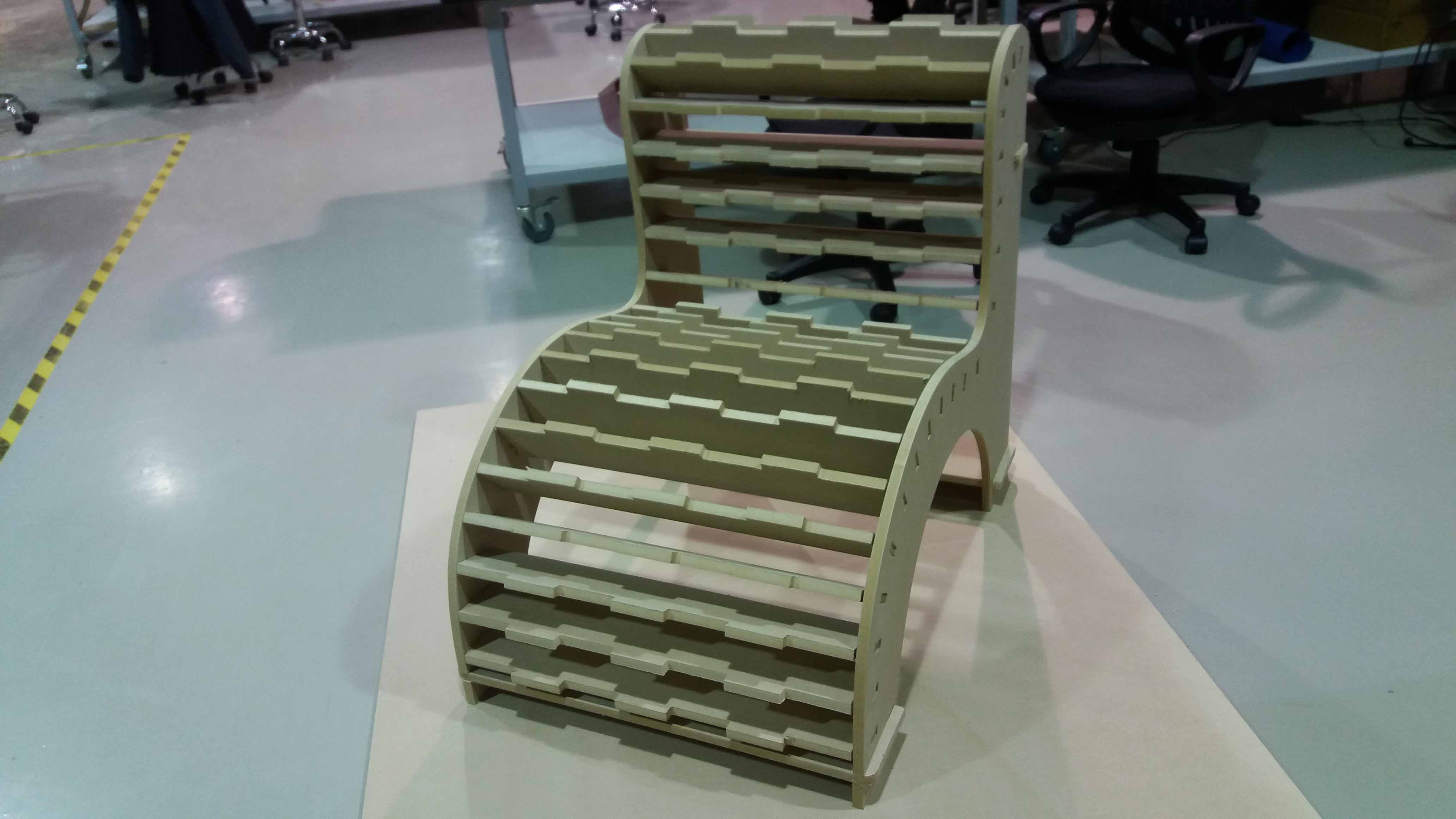
After the cutting is done, we proceed with the assemby. Water was used by inmersion to soften the material.
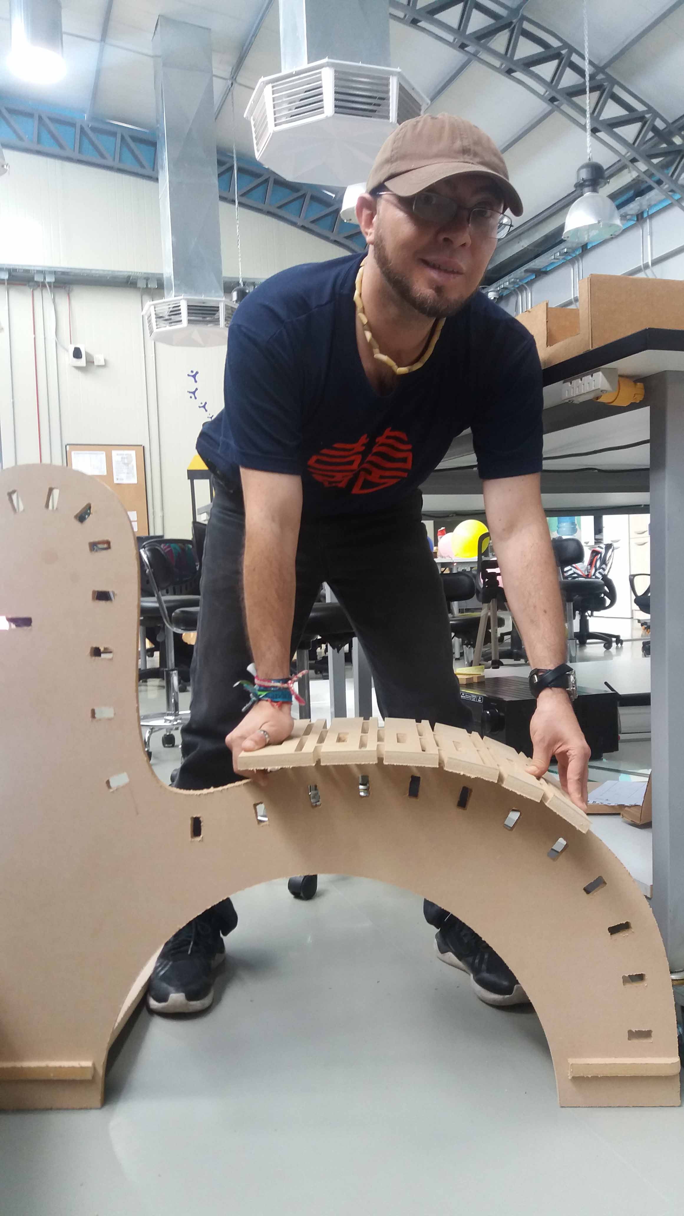
We locate the pieces and fit the tabs with the sloths. A rubber hammer is useful to the task.
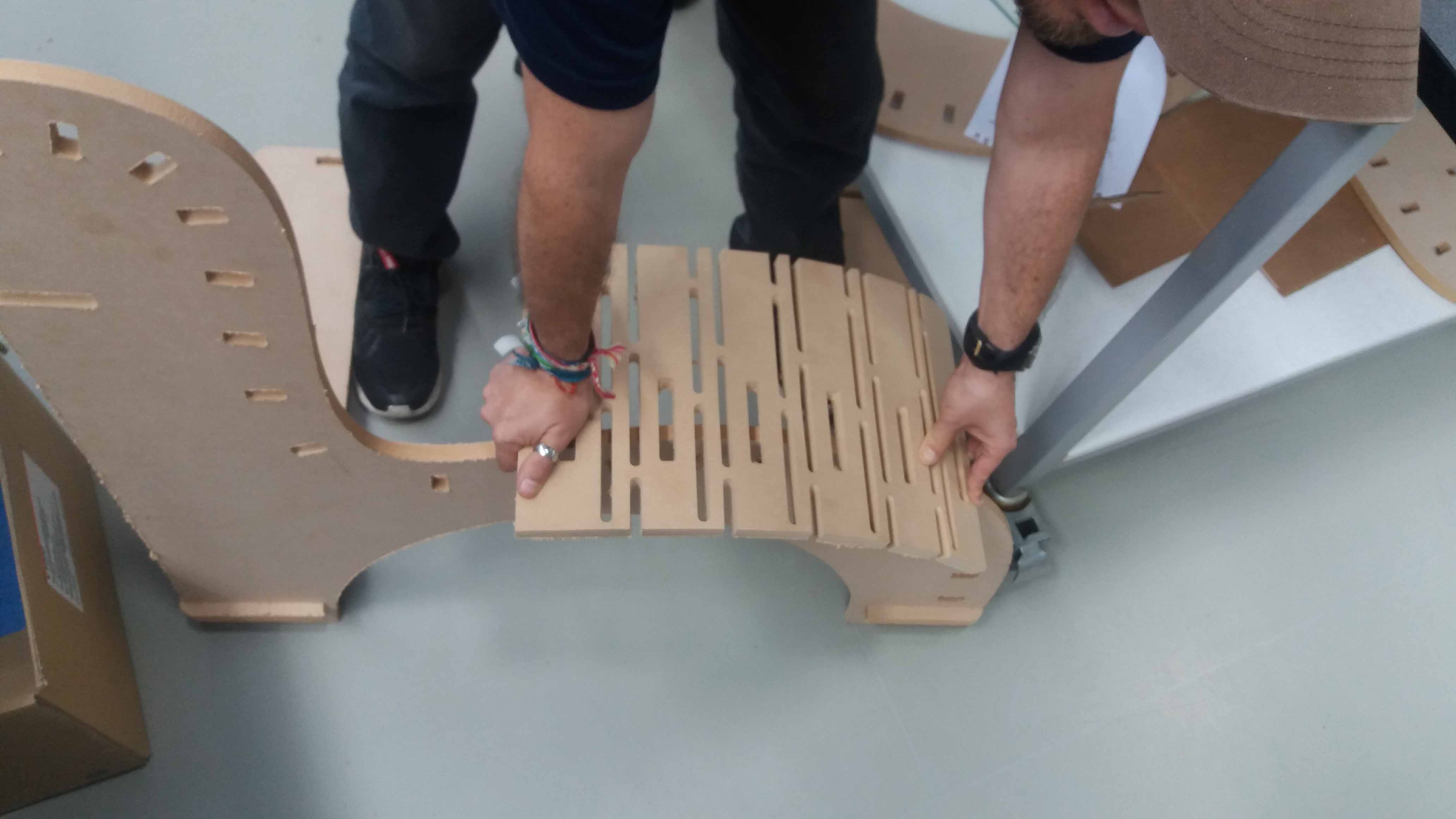
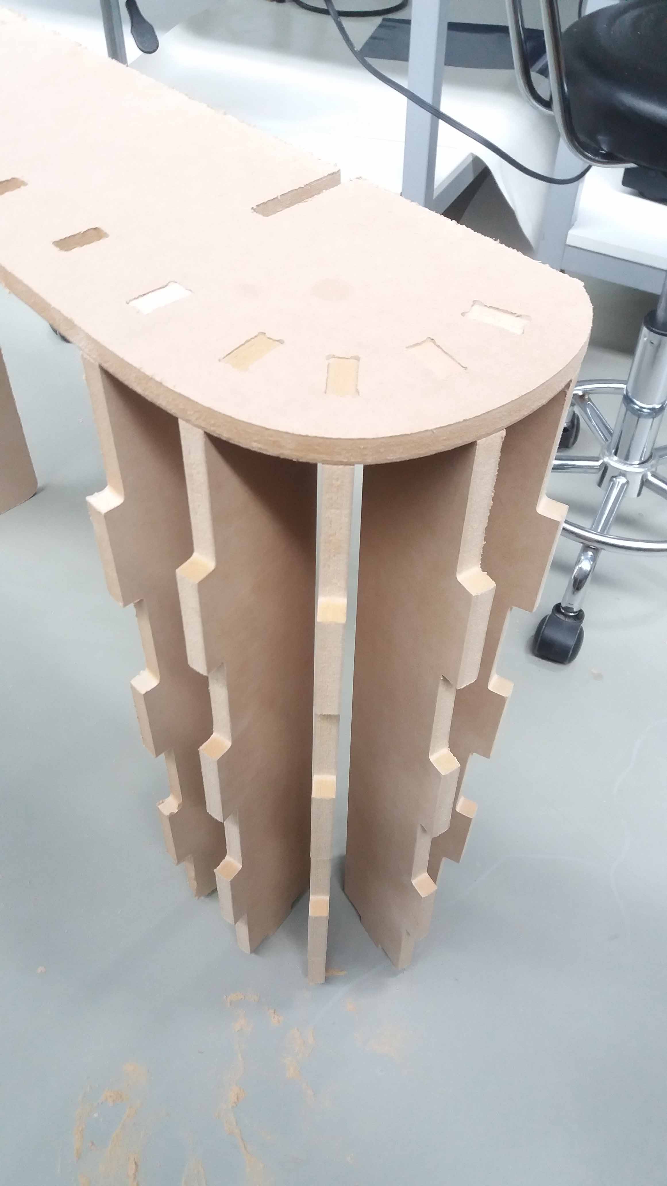
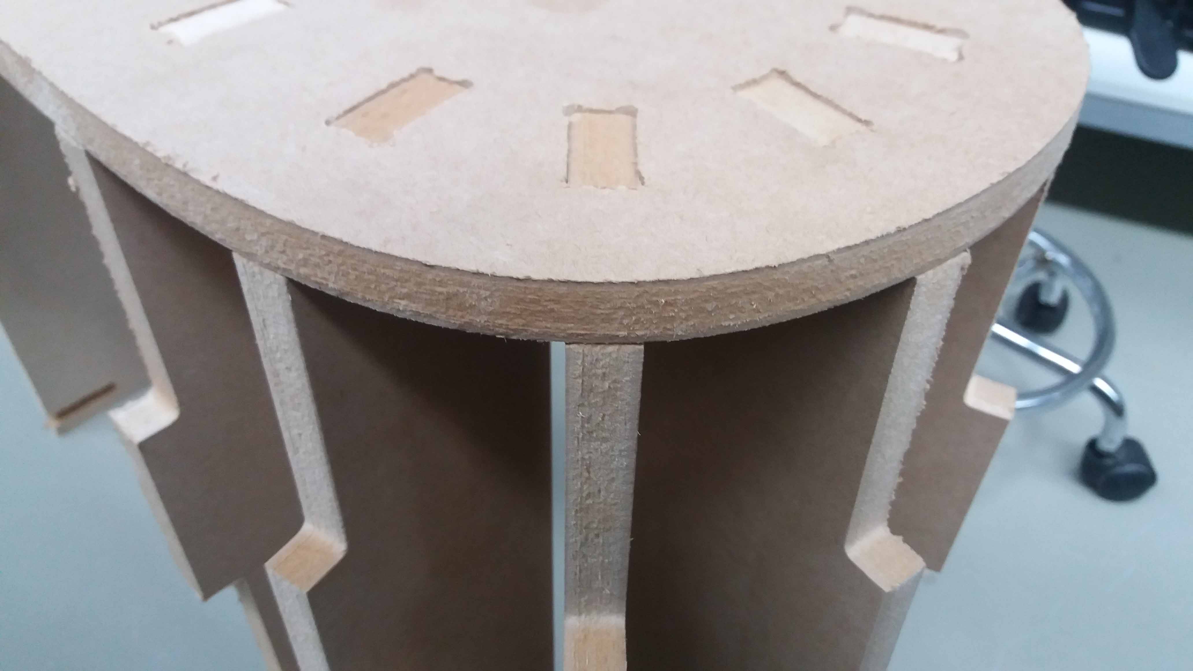
Here are some details of the cutting and assembling:
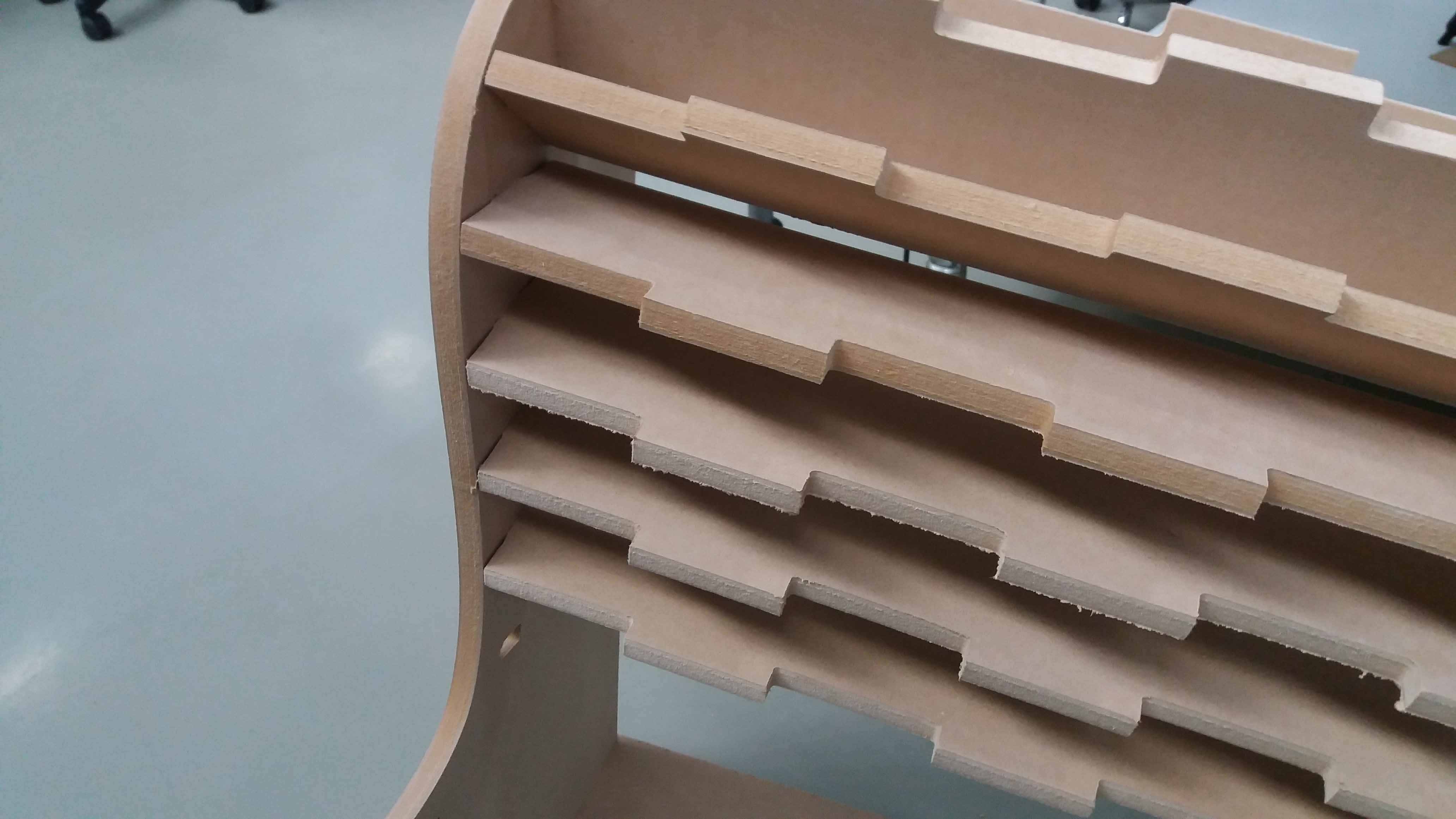
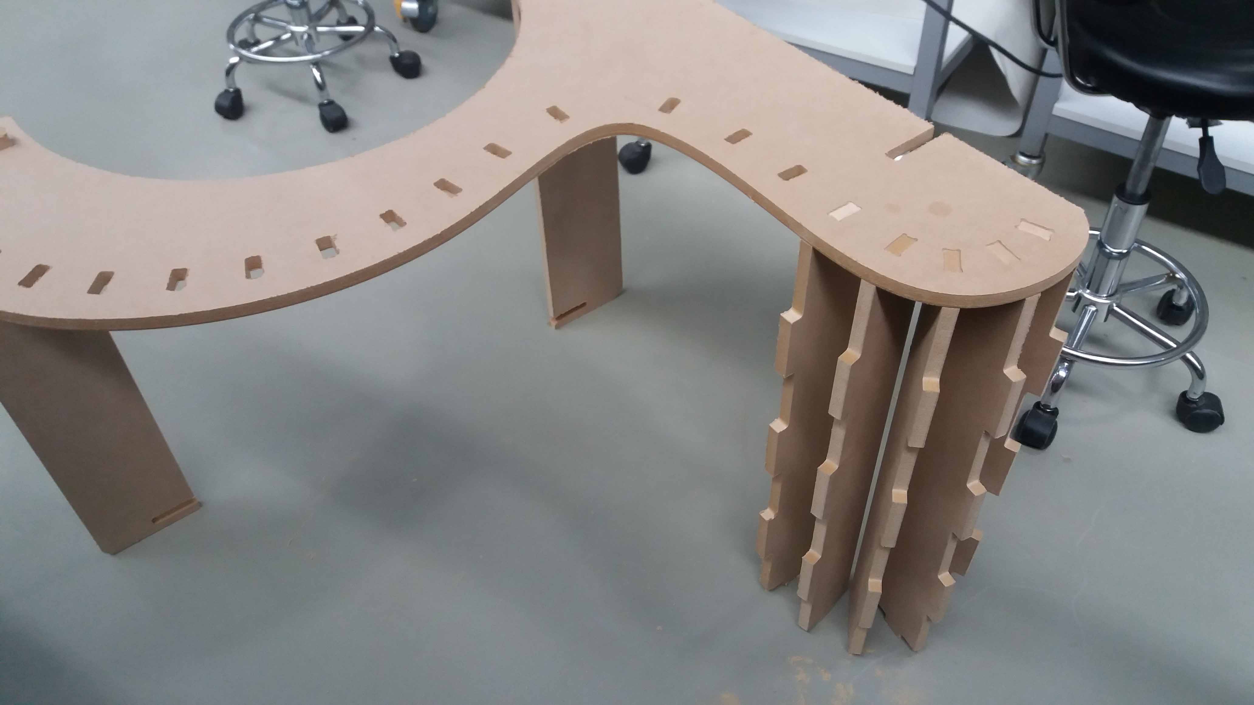
Two pieces of material were needed. Here we can see the cover cutting, and the ribs and sides assembled.
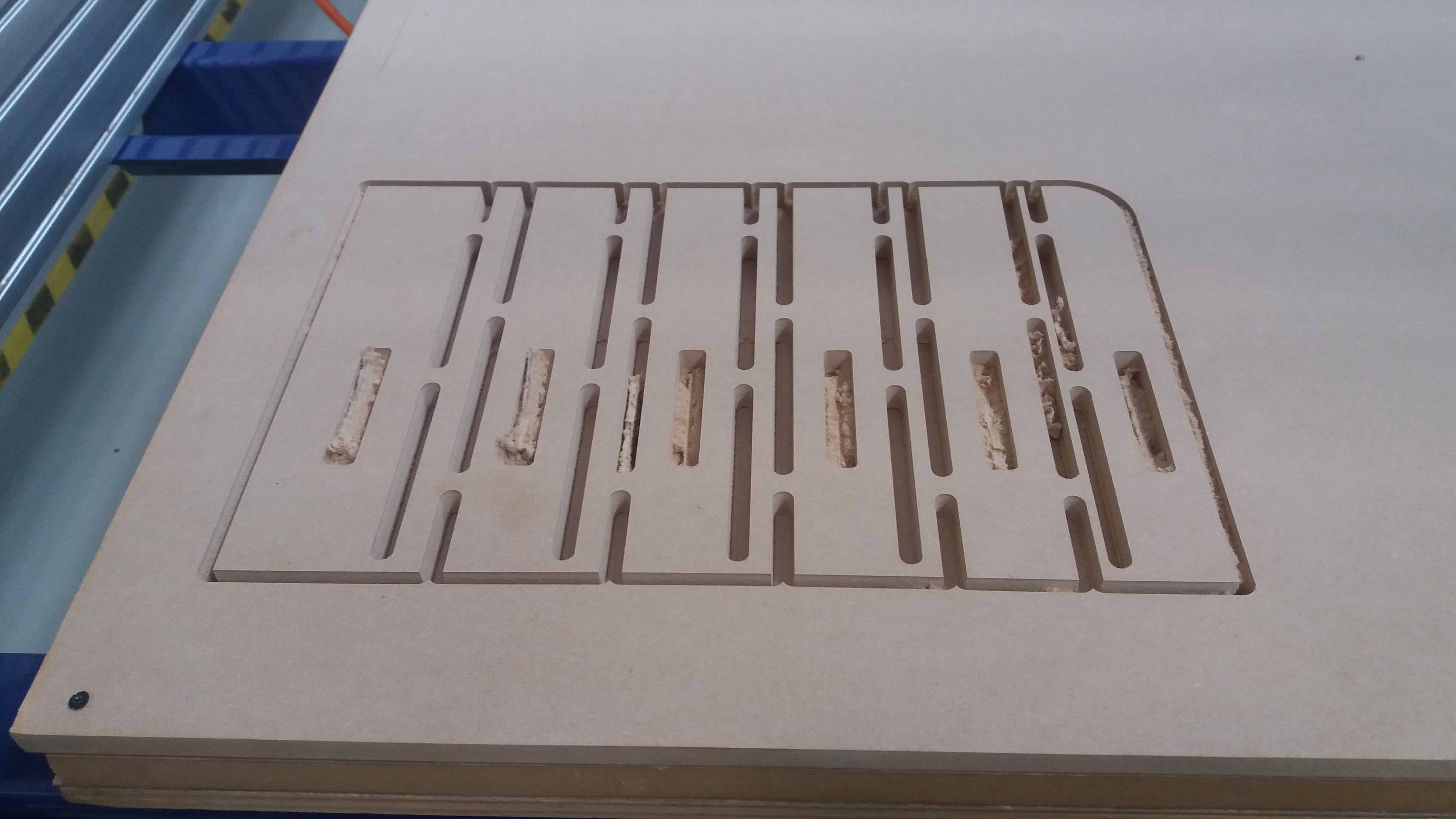
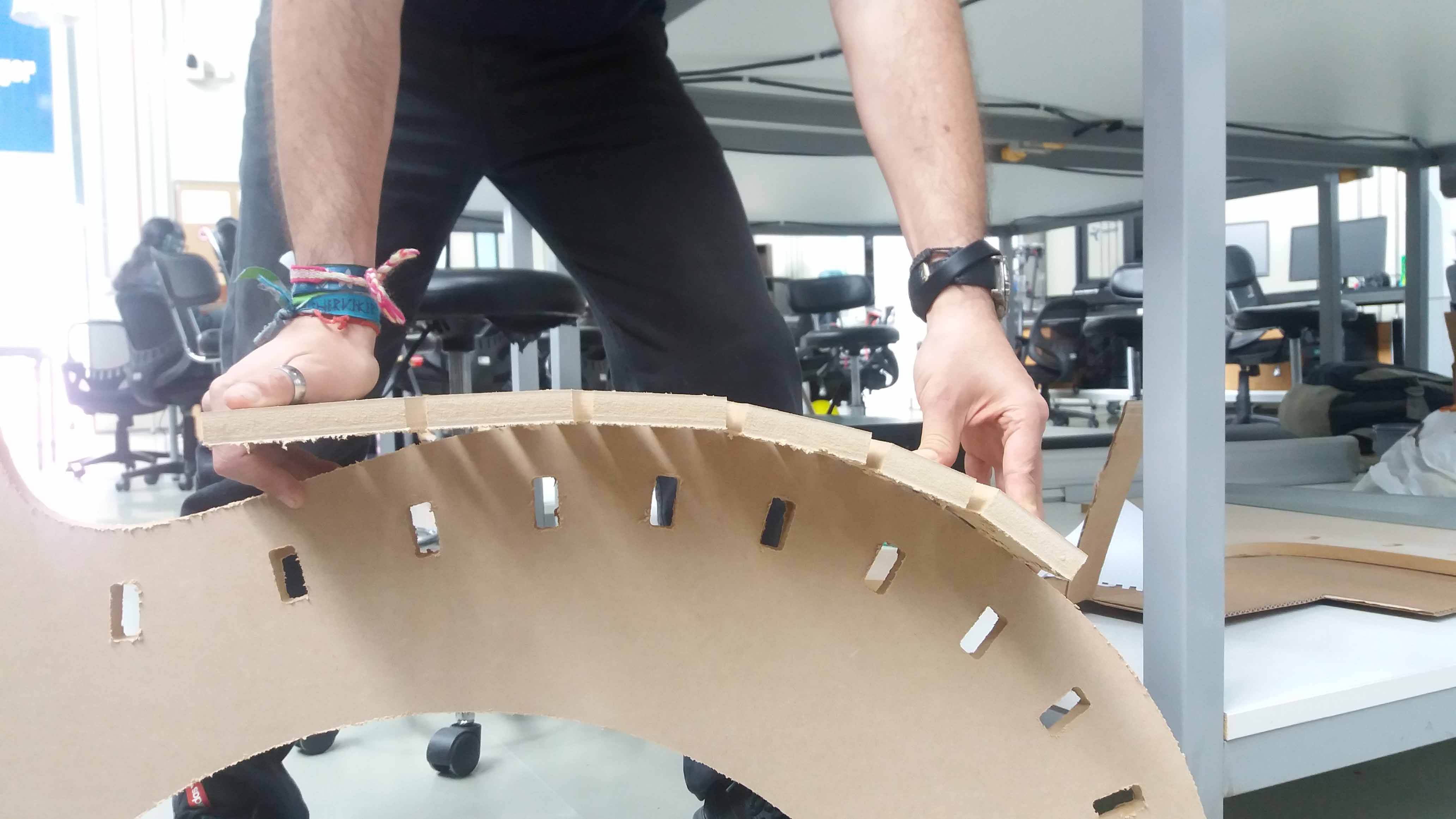
And finally, a detail of the living hinge cut and the chair almost completed.
I had some problems with the tab/sloth fitting of the covers. Looks like there was an error exporting the files to DXF files from Solidworks. This will be fixed for future fabrications.
The files used in this exercise can be downloaded from the following links:
Bend test SLDPRT,
Chair SLDPRT,
Chair A SLDASM,
Lower cover SLDPRT.

This work is licensed under a Creative Commons Attribution 4.0 International License.