
Nowadays we live an exiting time. It is possible to digitally model structures and then materialize them in plastic, ceramics, metal, wood, etc., and the list is growing. The concept of the interchangeability of bits to atoms, even allow us to design molecules.
That's why digital modeling is a nice skill to have, not only for digital fabrication, but also to perform physical analysis, and reduce the number of prototypes needed to reach the final product.
Have you:
Modelled experimental objects/part of a possible project in 2D and 3D software
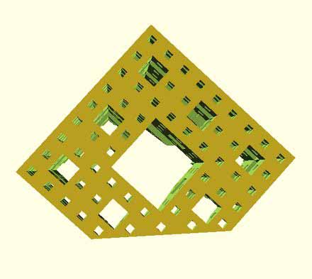
Yes. I have worked with Incscape for 2D objects in the past. Is good, lightweight and vesatile, but for complex conbination of objects I prefer the advantage a top-down design ofers. Ilustrator is other program that could export vector graphics files, used in 2D cutting. In 3D, I also tested Openscad. I think the progamatical aproach could be useful, for instance, for fractal generation. Here we see an example:
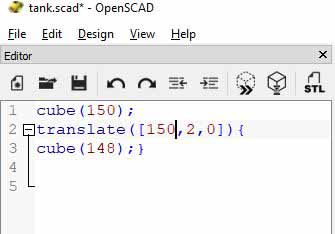
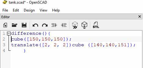
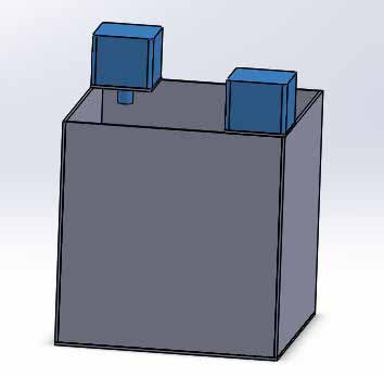
In this program, we use code for objects generation. To desing a tank, we can create two cubes with a few lines of code:
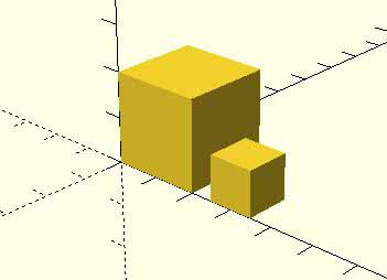
With the code:
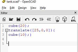
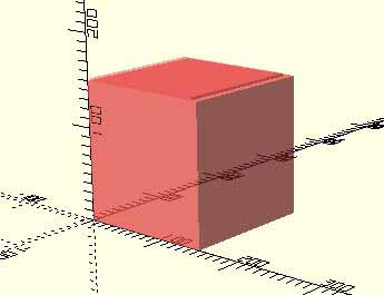
Playing with the code, we made two almost equal.
With the code:
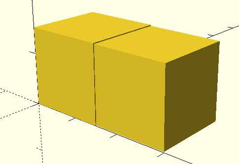
We move around a the cubes, and apply the difference function:
With the code:
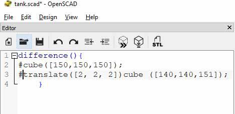
Note that we use # sign to make the objects visible. Finaly, we render it:
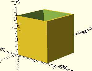
With the code:
Coding might be complicated at the beginning, but getting familiar with the language could allow us to design programatically very complex things. I might use it in the future.
Shown how you did it with words/images/screenshots:
I started by designing the tank where the injector (extruder) will print. I did so because I prefer to begin with the printable volume, and then proceed using a Top-down design approach.
I´m going to describe my workflow with SolidWorks. This is a top-down design, or in context design. The artifact is designed using pieces designed before in Assembly mode. Therefore, we can use previous geometry for the new pieces we create.
Here is a good tutorial for top-down desing learnig. Some might find it helpful:
00. I´m going to start with the tank structure designed previouslly.
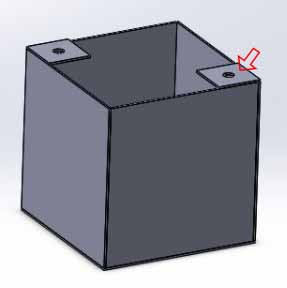
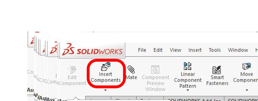
01. Then, I used the new part command, under Insert components tab.
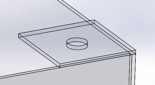
Then, clic on the surface you want to use as a reference for the new part. In this case, the surface marked with an arrow.
02. Using the convert entities tool, select a closed contour. It will be transferred to a new sketch, where it is possible to use it as any other sketch.
That lead us to a sketch that uses that surface as a plane of reference. Use the convert entities tool to make a closed contour on the new sketch created.
03. Then I extruded the entities converted (square) and extruded it 3.38 cm (the hight of the actual motor).
Extrusion result:
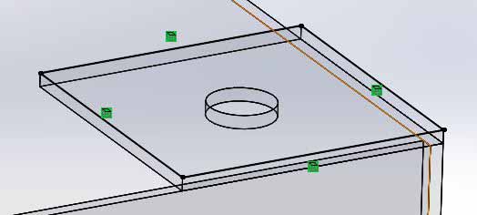
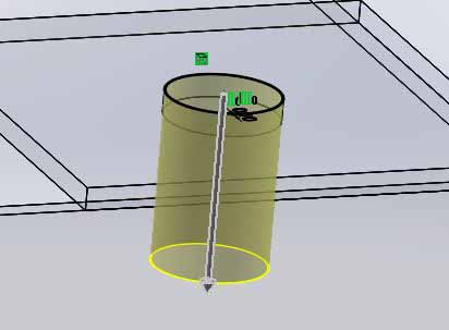
04.The next step was right-clicking the new part and choose hide. That way, we access the hole from the previous structure. Then we can select the cirle:
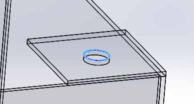
05. Then, we apply the tool convert entities. That way we have the measurement translated to the plane sketch we are working with.
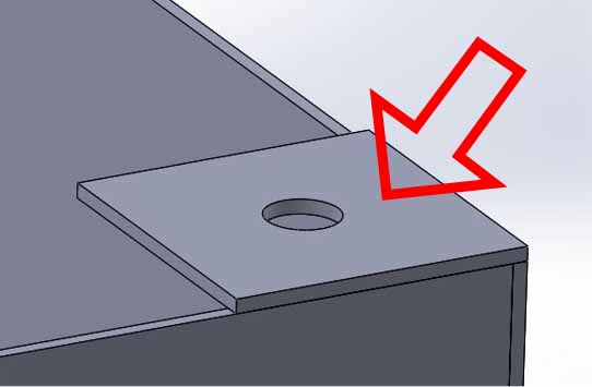
06. Apply offset entities to the circle (reverse, or offset to make it smaller). We can see the offset in yellow.
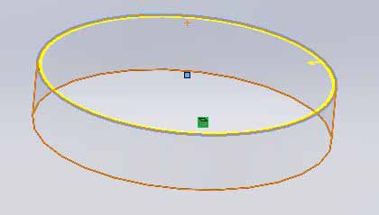
The offset is going to be 0.1 mm. This is the resolution of the laser cutter and the 3D printer. This allow us some space to insert the shaft of the motor (our new part).
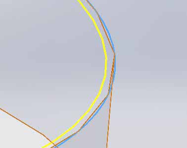
This is a close up showing the offset.
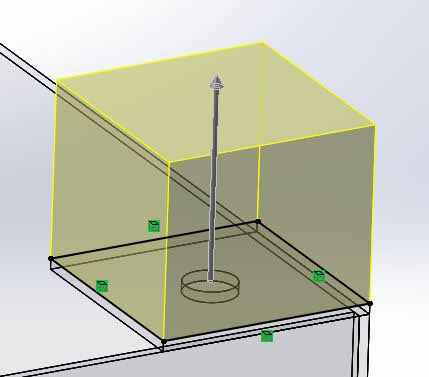
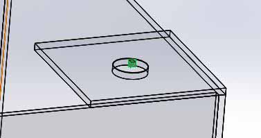
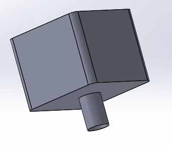
07. We use the extruded boss base command to extrude our circle downwards (change the direction if necessary), and choose Merge result in the dialog window on the left. This way, our extrusion is going to fuse with the cube we made previously. The extrusion was arbitrary 15 mm. We can change that later depending on future design.
Extrusion result:
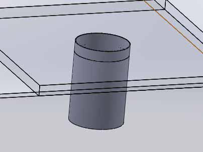
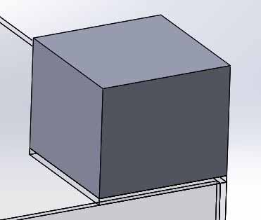
We make our cube visible again (no pun intended), choosing it from the working tree. Remember where you hide your pieces, otherwise is hard to find them after some workflow. Here is the created part in context:
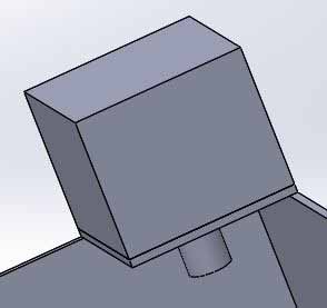
Marked in blue:
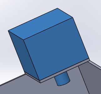
We created a virtual part. For easy use, future design or reuse (we will see this later) we save this as a “real” part. Virtual parts are recognizable because of they are between brackets. A right-click on it´s name allow us to Save Part (in External File). Once it is done, we can open the part in part mode, and continue editing. I did so, and applied some fillet (so it resembles the stepper motor we are modeling).
If we go back to the assembly, we can see our changes are reflected there too.
It is possible to make a part independent, but it is not the scope of this review. I am going to use the individual parts of the tank assembly (bacically 2D extruded) for vector graphics generation of 2D parts, ready to laser-cut. Complex 3D parts will be printed. Note: this part will be made not further complex. Is just a representation of a physical part, and we are interested in it´s exterior geometry only. Reuse: once our part is saved, we can reuse it in the assembly (or other assemblies). We could place it where mates allow us to do. Here is an example for the stepper motor for the other axis:
2D software experimentation
Here we experiment with 2D software for creating 3D objects. I'm going to use Inkscape, that, besides to be very intuitive, it allow us to make very precise objects. Moreover, it's open source.
First, we use an example form the program Linkage, that can be downladed here.
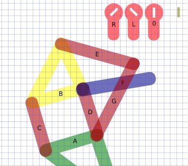
We are going to use the Theo Jansen mechanism offered as example in the program.
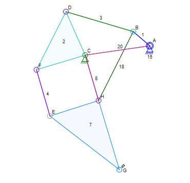
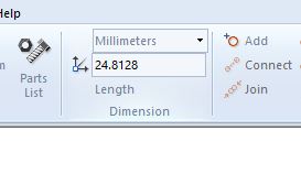
If we clic in one of the components...
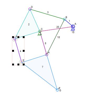
... we can see its dimensions in a windows at the top
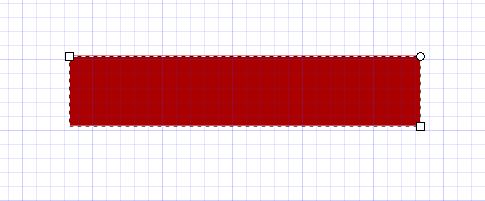
We can export this as an image file, and import it to inkscape, for use as a guide. In inkscape, we create our parts form primitives.
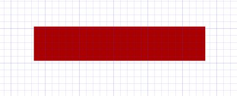
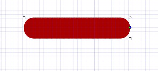
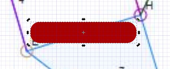
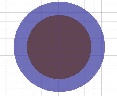
If we clic in the primitive, we can see handles that allow us to create rounded corners. We drag them to the center, and we have our basic piece.
 \
\
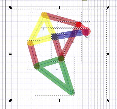
Then, we locate it and orient it over the image imported in inkscape.
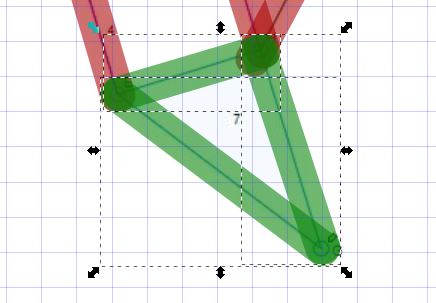
We continue creating pieces and locating them on the graphic imported.
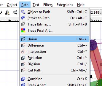
We can select more than one piece, and fuse them together with the command --> path ---> union.
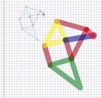
We are going to scale the mechanism in this point. We select everything...
...And scale it by 150%.
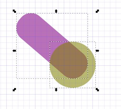
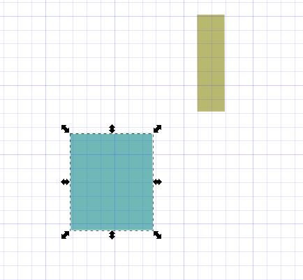
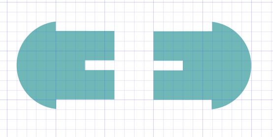
For the holes, we use a reference of a piece with the with and thickness of our material.
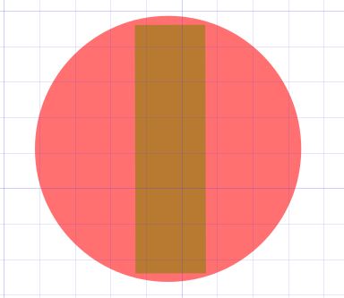
We use this circle to "bore" holes in our pieces, with the command --> path --> difference.
And continue to do so with the other pieces.
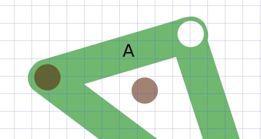
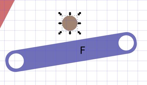
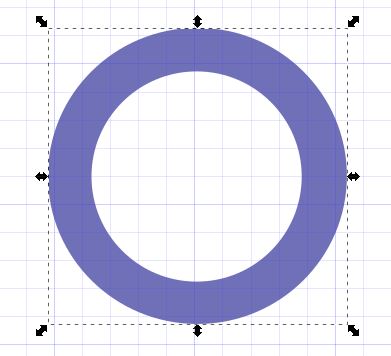
This mobile piece is going to provide power and movement to our construction. We made it with our primitive modified with the command "union".
And use the command "difference" to create the hole for the axis.
We create two more symilar pieces at an angle of 45° to the right and to the left. This is going to provide tree positions for the movent of (at least) three legs.
We are goint to create a washer too. This will be a circle with a hole.
And then cut it off with the "difference" command.
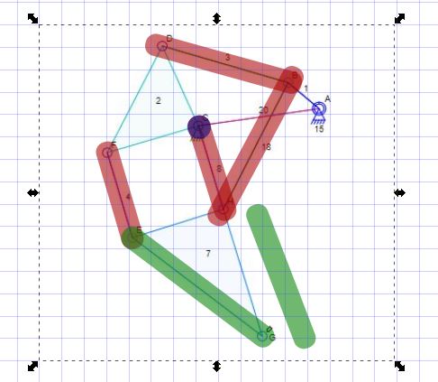
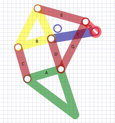
Here, we see all the pieces in position and with their corresponding holes.
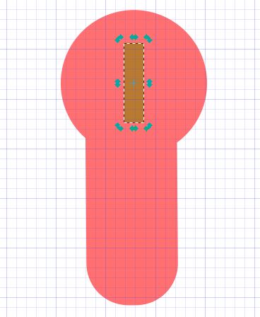
For the pins that will hold everything together, we use a 7mm wide piece as a reference, and set the limiting head and a sloth on it.
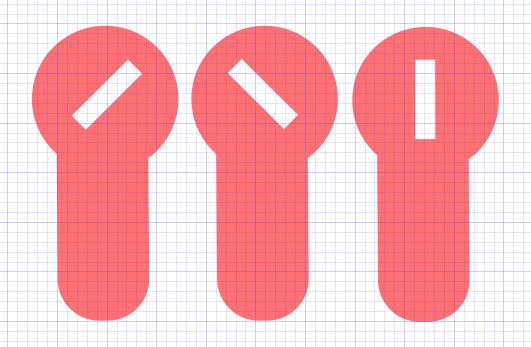
And then we create a copy and horizontal mirror it.
The piece we created is designed to hold 3 pieces (6mm). For holding 4 pieces, we create another variation, 2mmm longer. We modify new pins/axes according to our needs.
Opcionally, we name our pieces. This will be usefull for emssemble it.
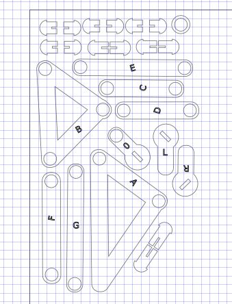
Then, we arrange them so they occupy the less space possible.
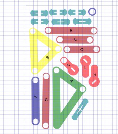
For cutting, we select all, eliminate the fill and set the line with to 0.001 inches (0.025cm). We duplicate the pieces "C" and "D". We are going to need two to them, for the constructions to be robust. (in the image, a slightly wider line width was used, for demonstrative purpouses).
Conclusions about the use of diferent sofware
I started my journey in digital object design with Solidworks and Inkscape.
In the Fabacademy experience, I had a chande to experiment with other software. With Fusion 360, the creation of parts (called components, in this software), can be done in context, as in Solidworks, but the relationships between the components is diferent. In solidwoks, the relashions (called mates, in Solidworks) is made using a coordinate plane to define the geometry. In Fusion 360, each componentst is defined in relation to other component. The learning curve was quick. I personally find booth useful, and I think is good to know both.
There are also other resources, specially online. The Solidworks version online, or the chance to colaborate using Fussion 360 on the cloud are some examples. I tried some of them, but my internet conection is poor, so I had to rely mostly on the local installed Studend Version of Solidworks for Students.
Using the sofware I realized the importance of parametric design, specially when the design is subject to variables, like the width of a 2D material. On the other hand, the posiblilty of create your own scripts in Inkscape could make it parametric (somehow?).
I also started to use Blender. I think it is a good program for visuals, but not so useful for machine implementation design. On the other hand, interesting thing could be made using programming, as it is compatible with Python.
I still want to try other sofware, like Grasshopper and Rhino.
As a conclusion, I could say that undestinding the concepts could help you to learn a new program easier. Like computer languages, if you understand the basics, getting the way a new one works make sense and is easier to grasp.
The documents from this page can be found here:
Tank Basic,
Tank Modified,
Base. Solidworks part,
Aluninium extruded bar. Solidworks part,
Aluminium bar,
Base SW,
Major Side SW,
Minor Side SW,
Rod SW,
Silk Printer. Assembly,
Silk tank,
Stepper,
Stepper support,
Tank SW,
Transversal.
Theo Jansen Sandbeast in process.
Theo Jansen Sandbeast compacted.
Theo Jansen Sandbeast for cutting SVG.
Theo Jansen Sandbeast PDF (cutting).

This work is licensed under a Creative Commons Attribution 4.0 International License.