Azolla is a unique plant that can help reduce man-made climate change and provide biofertilizer, livestock feed, food and renewable energy anywhere in the world.
Azolla is a unique species it is one of the fastest growing plants on the planet – yet it does not need any soil to grow.
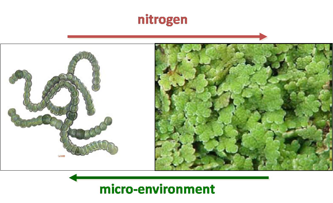
Unlike almost all other plants, Azolla is able to get its nitrogen fertilizer directly from the atmosphere. That means that it is able to produce biofertilizer, livestock feed, food and biofuel exactly where they are needed and, at the same time, draw down large amounts of CO2 from the atmosphere, thus helping to reduce the threat of climate change.
Azolla is able to do this because it has a unique mutually beneficial ‘symbiotic relationship‘ with a cyanobacterium (blue-green alga) called Anabaena.
Each partner gives something to the other in this Perfect Marriage.
Azolla provides an enclosed environment for Anabaena within its leaves. In return, Anabaena sequesters nitrogen directly from the atmosphere which then becomes available for Azolla’s growth, freeing it from the soil that is needed by most other land plants for their nitrogen fertilization.
The oldest Azolla fossils are more than 70 million years old, representing the remains of plants that lived during the Late Cretaceous Period when dinosaurs roamed the earth. They occur in sediments that were deposited in quiescent freshwater bodies, such as lakes, ponds and sluggish rivers, identical to those inhabited by modern Azolla.
Azolla and Anabaena have never been apart for 70 million years. During that Immense period of time, the two partners have co-evolved numerous complementary ways that make them increasingly efficient.
That is why Azolla is able to produce large quantities of biofertilizer, food, livestock feed and biofuel without using land needed to grow food and biofuel, or natural ecosystems such as rainforests.
Vigyan Ashram has also worked on azolla before, and there is a continuous cultivation of azolla almost all throughput the year
When I started reading about azolla cultivation in Vigyan Ashram I came to know that it takes ~15 days for the biomass to double.
On the internet people have achieved doubling of growth in ~3days
I took this as a challenge, and decided to optimize growth time of azolla
Hence:
THE Azolla Experiment:
To skip all the nontechnical stuff and go directly to the summary of the project click here
To skip directly to the technical stuff, click here
To check the update after comments from global evaluator, click here
In ashram there are 3 places where azolla is cultivated.
With the help of agricultural interns, I collected samples of water at these places.
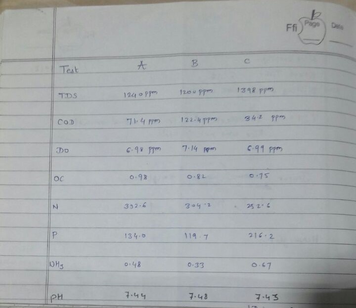
This was then tested for pH , COD (Chemical Oxygen Demand) , DO (Dissolved Oxygen) , Nitrogen , Dissolved Phosphates , TDS , OC.
1: Sample A is where cultivation of azolla is done traditionally, unlike expected (which is 2x biomass in 3-4 days) it takes almost 10-12days
2: Sample B is based and similar to A but here azolla is cultivated in an open environment i.e without any shade. Also the beds size is small. Here also it takes similar amount of time to cultivate.
3: Sample C here Azolla is is not cultivated per se. This is a refuge tank for aquaponics, azolla is dropped here before feeding to the fishes. This place is very near to my dorm. I have personally observed rapid growth here. That is why I have taken water sample from this place too.
Results:
Sample A
Sample B
Sample C
TDS
1240 ppm
1200 ppm
1398 ppm
COD
71.4
122.4
34.2
DO
6.98
7.14
6.99
OC
0.98
0.82
0.75
Nitrogen
332.6
304.2
252.6
Dissolved Phosphates
134.0
119.7
216.2
pH (pouvoir hydrogène)
7.44
7.48
7.43
I knew empirically that azolla grew very well in the sample C. Lets called in aquaponics water for now.
Aquaponics water is quuitew different in many aspects when compared to the other systems.
High Dissolved Phosphates
very Low COD
High TDS (could be Dissolved phosphates)
Near constant circulation of water
I read a few things on the azolla foundation website available here
Using simple logic I decided to do a an experiment
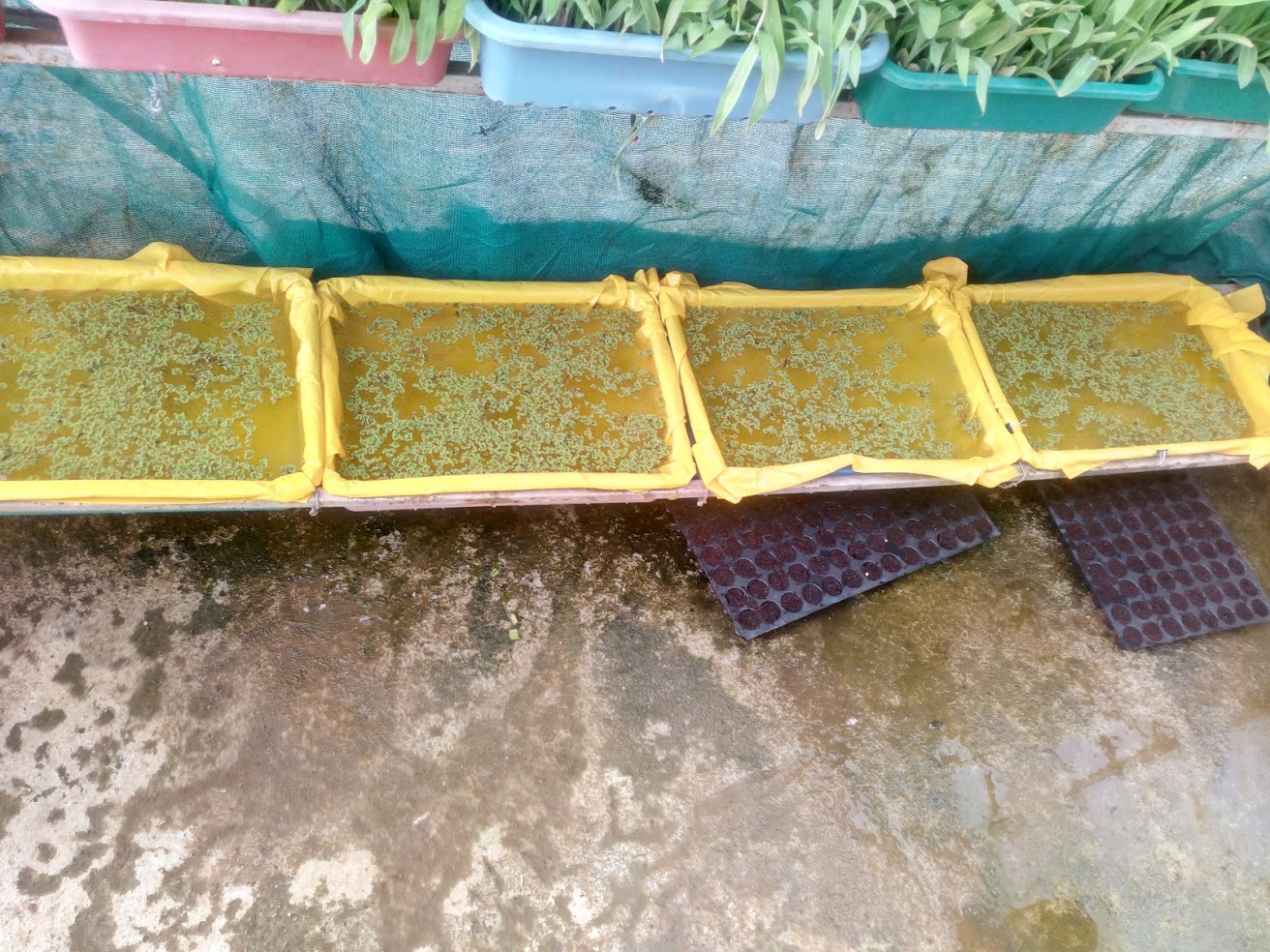
I decided to make 4 beds of azolla.
These were to be kept in polyhouse like structure, for high humidity
50gm Azolla (wet mass) + Normal Water
Control bed.
50gm Azolla (wet mass) + Aquaponics water
To Calculate the time taken to double biomass.
50gm Azolla (wet mass) + Aquaponics water + Super Phosphates
To see if just adding phosphates will boost the yield.
50gm Azolla (wet mass) + Aquaponics water + Super Phosphate + Some algae
To verify that increasing the COD will reduce the output.
Results were checked after 3 days, and were surprising!!
Tray 1: 50gm to 60gm
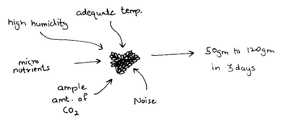
Tray 2: 50gm to 120gm
Tray 3: 50gm to 92gm
Tray 4: 50gm to 70gm
I had basically achieved the goal :P without any efforts. Now I was more confused.
The tray in which nothing was modified grew the best.
I, with help of my colleagues (8-10 people) created a fish-bone like diagram. In which we discussed -
Possibles reasons for the results
Other conditions for rapid growth
I didn't know the exact reason why it grew so well.
This is what I believed caused the rapid growth.
Upon going into detail, there are a few things I noticed.
I was sharing the polyhouse with a hydroponics system.
This system was being watered (sprayed) 4 - 5 times everyday.
There was a light which would glow in the night
Temperature could have been maintained 24hrs, photosynthesis could have been carried out 24hrs a days.
Lots of water was also sprayed on my beds.
Increased DO of the water could boost azolla growth(?), Azolla grows by vegetative propagation. Water might have accelerated this by breaking leaves more often.
Micro nutrients from fish waste.
This water could be already rich in micro nutrients due to presence of fish waste.
With the new knowledge in tow I decided to perform a full factorial DOE (Design of experiment)
I consulted with two mentors here at Vigyan Ashram, Dr. Arun Dixit and Mr. Ranajit Shanbaug.
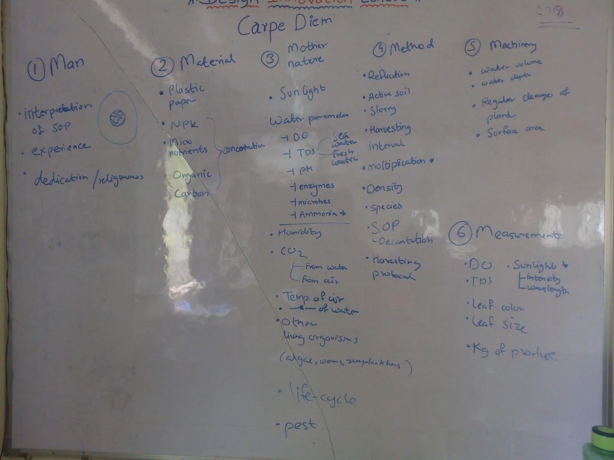
We decided to do a fishbone diagram.
One day when everyone was free, The Agriculture Intern, DIC Research Fellows, Fab Academy Students almost a total of 10 people and Dr. Dixit and Mr. Shanbaug we performed the exercise where we drew a fishbone diagram.
Modified fishbone diagram to fit well on the whiteboard.
Of the above, we decided to control only 4 factors as they can be cheaply/easily controlled (even on large scale).
In ashram we cannot control everything as accurately was we want, due to weather/cost or random problems.
Hence noise is an important part of the experiment.
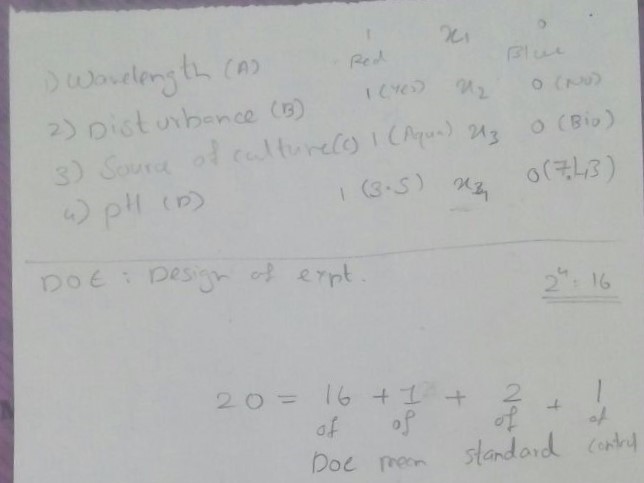
The factors we selected were:
More clearly,
Wavelength of light Incident
spraying of water on surface (forced vegetative prorogation)
Source of micro organism culture
pH of the water present.
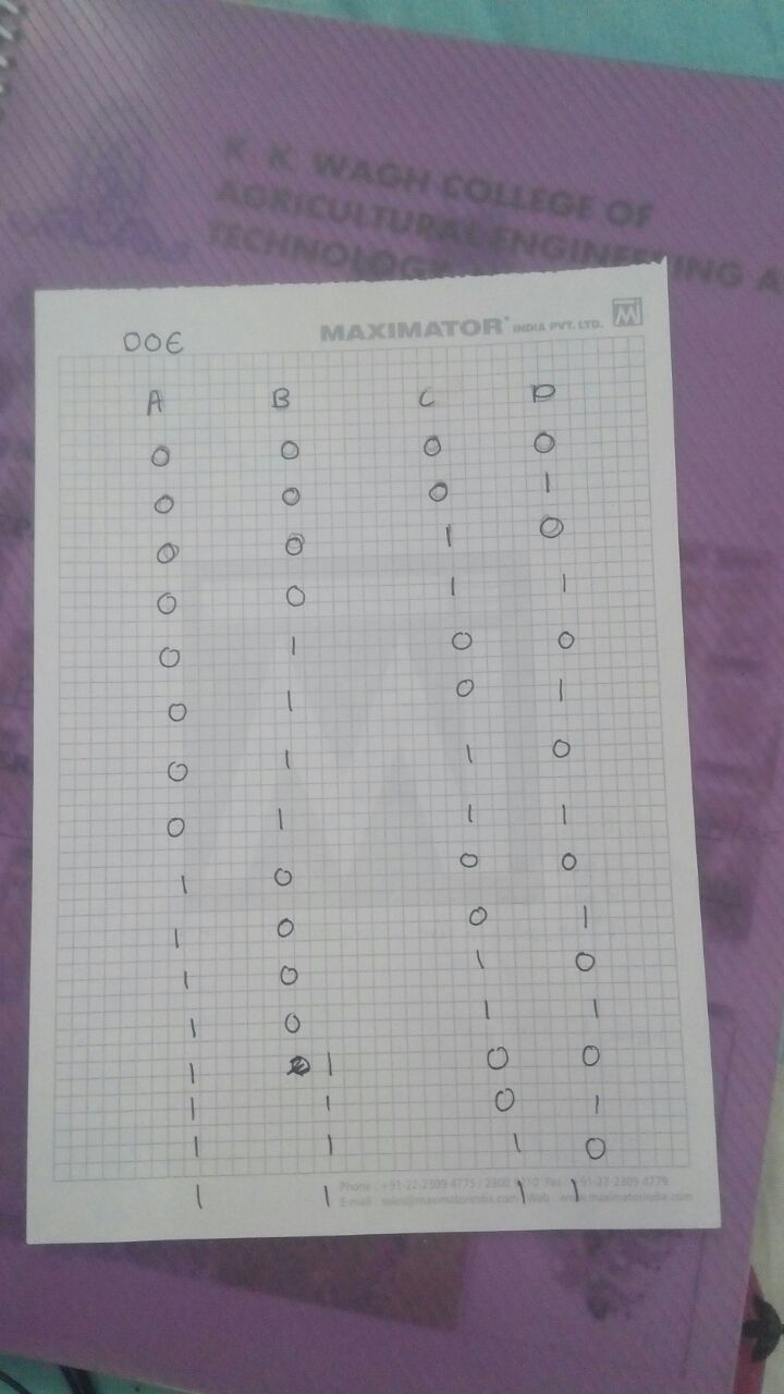
The DOE was to be performed in the following way
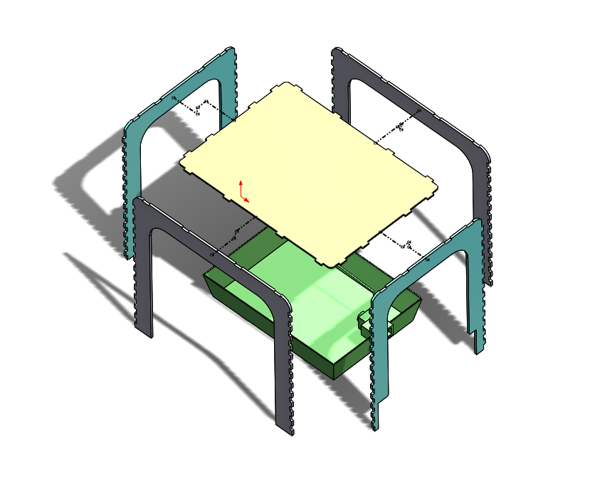
I decided to make a system like a small polyhouse to control all these parameters.
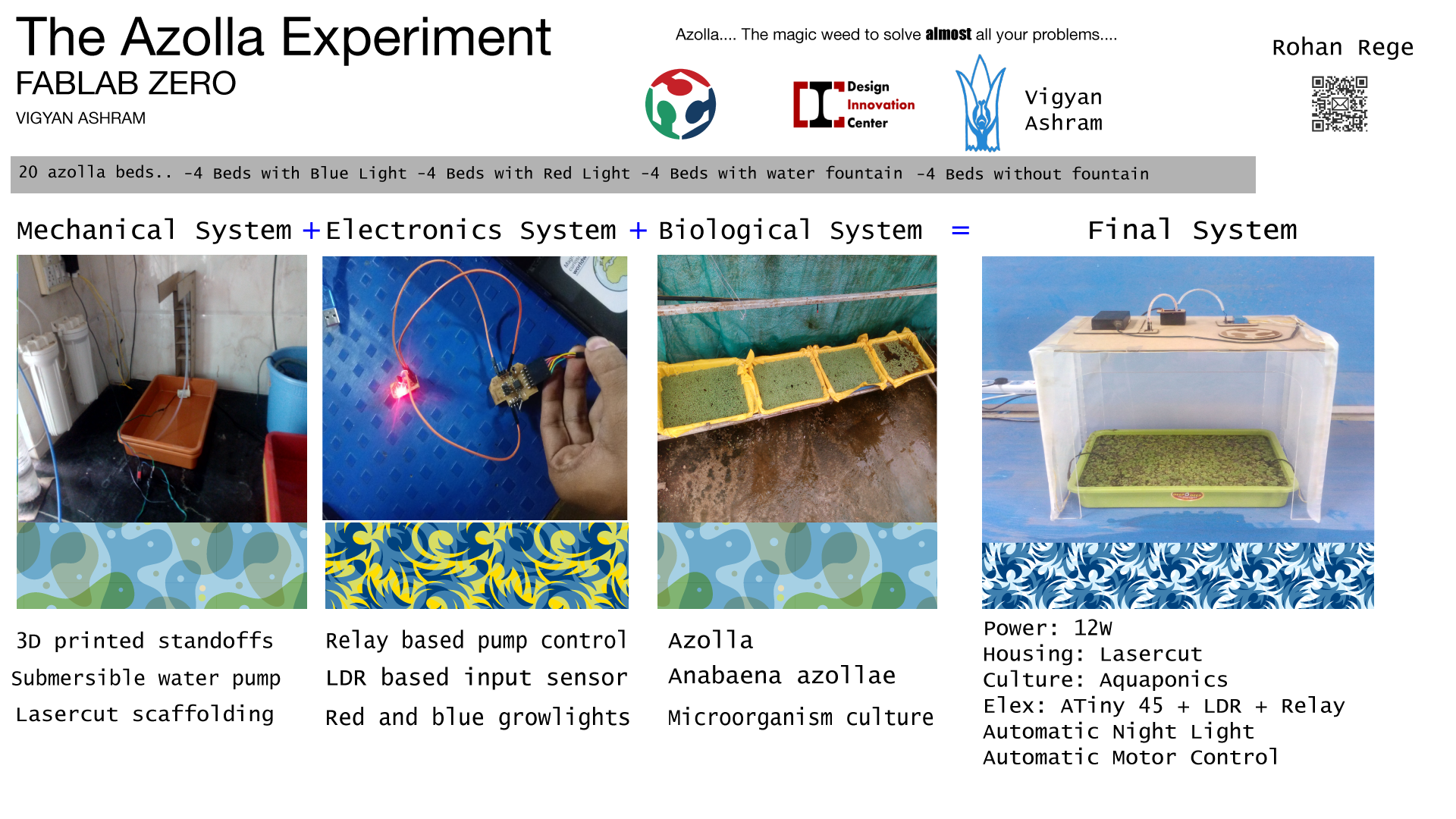
I decided to divide the project into 3 different parts
Mechanical
Structure, Water Pump selection, polyhouse cover.
Electronics
Calibration of LDR, Program for Motor, Smoothing of output.
Biological
Selection of adequate culture, adequate water level, etc.
I am working on all these individual components.
I am to executing (and executed some) these systems individually and then, combine them to make the final project
Important stuff:
Project Deadline: 14th of June
Completed tasks:
Mechanical Structure
Electronics Assembly
Remaining tasks: (As of 11th June)
Selection of paper for polyhouse
Electronics Programming
Cable management
Working Status:
What is working?
The lasercut structure is fitting.
The electronics fits perfectly in the 3D printed box.
Azolla planted in beds in a nearby polyhouse is growing well
What is not working?
LDR is not as perfectly calibrated,(to my liking)
There are some issues with pressfitting durability
What questions need to be resolved?
What to do of all the azolla we have cultivated.!
Will the water pump cause issues with the circuit
Will there be a short circuit due to improper wirings
Learning outcomes:
I had a refresh of my knowledge of 3D softwares.
I learned the basics of 3D printing, found out how to set parameters for different quality of prints
I felt I did a short course in electronics engineering.
The tendency to keep short goal, achieve the satisfaction and hop on to get the next one
The tendency of people to expect exceptional in the least possible provisions
Machines are machines not humans
Electronics System:
Open electronics is always a weakness for me.
I like it when the circuits are exposed.
I decided to implement similar system.
One needs to be careful while doing this.
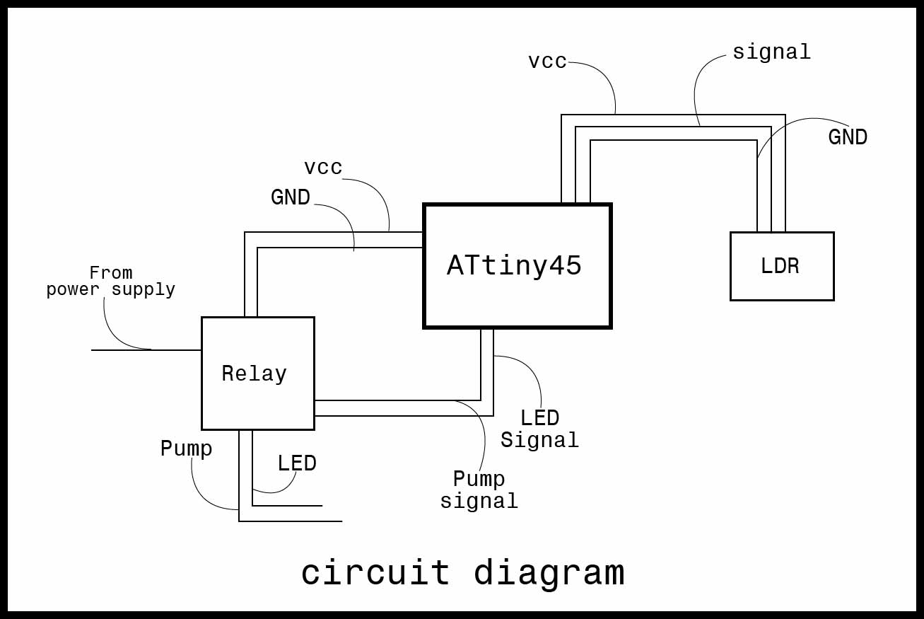
My electronics conatins only a few parts.
12V Power supply
LDR circuit
Microcontroller PCB
Power switching circuit
The microcontroller board is designed previously in Input/output assignment, Scroll below for sources, assignment link here
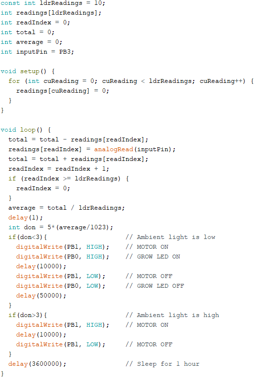
The Micro controller takes input from the LDR, to know if its day or light.
If its night, the micro controller turn ON the LED for 10 secs in a minute. (10sec on, 50sec on loop)
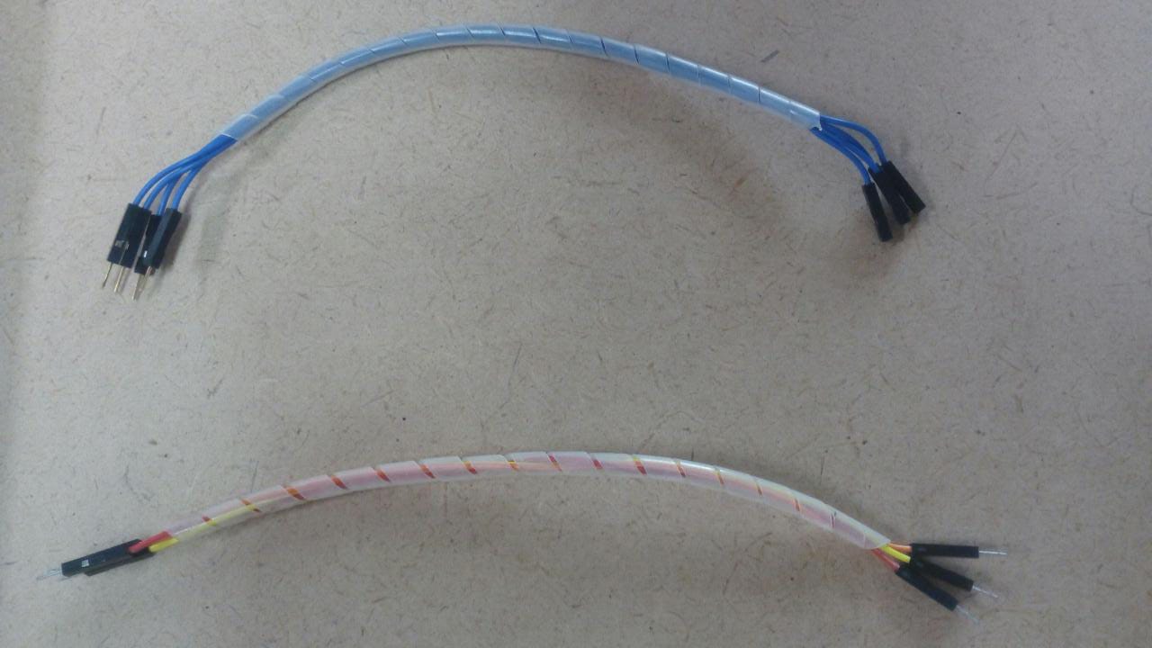
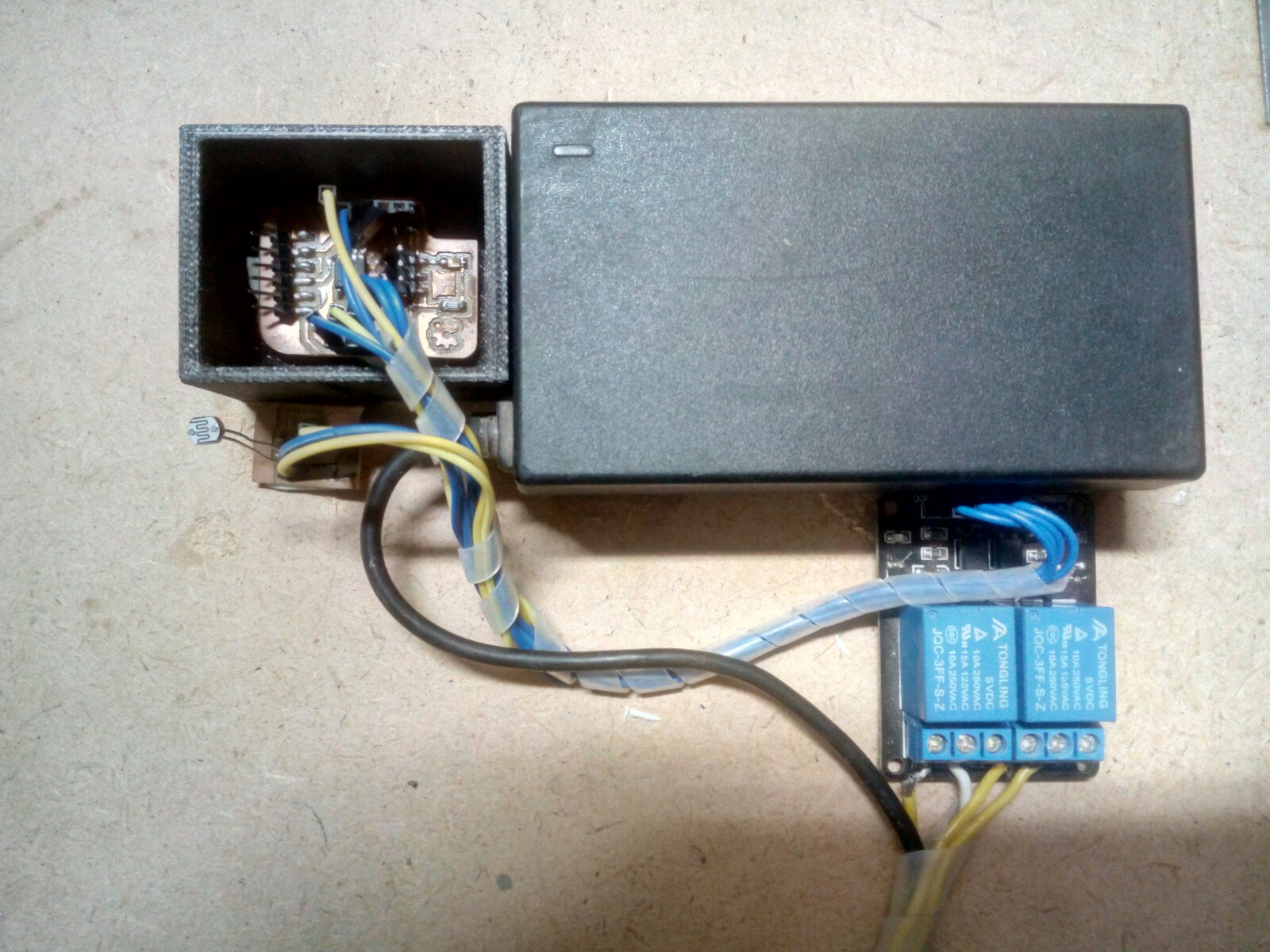
I grouped all the wires together.
Then used a plastic sleeve to hold them together. The sleeve will protect them from the environment.
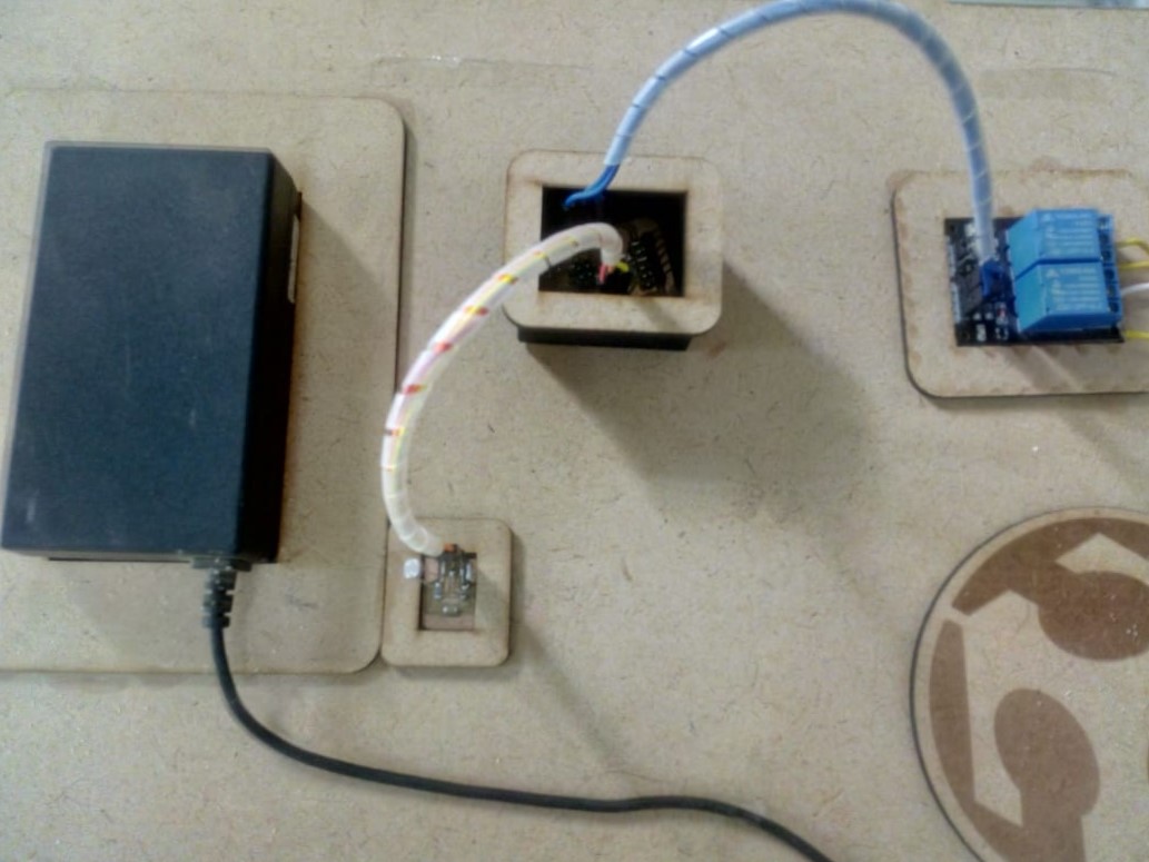
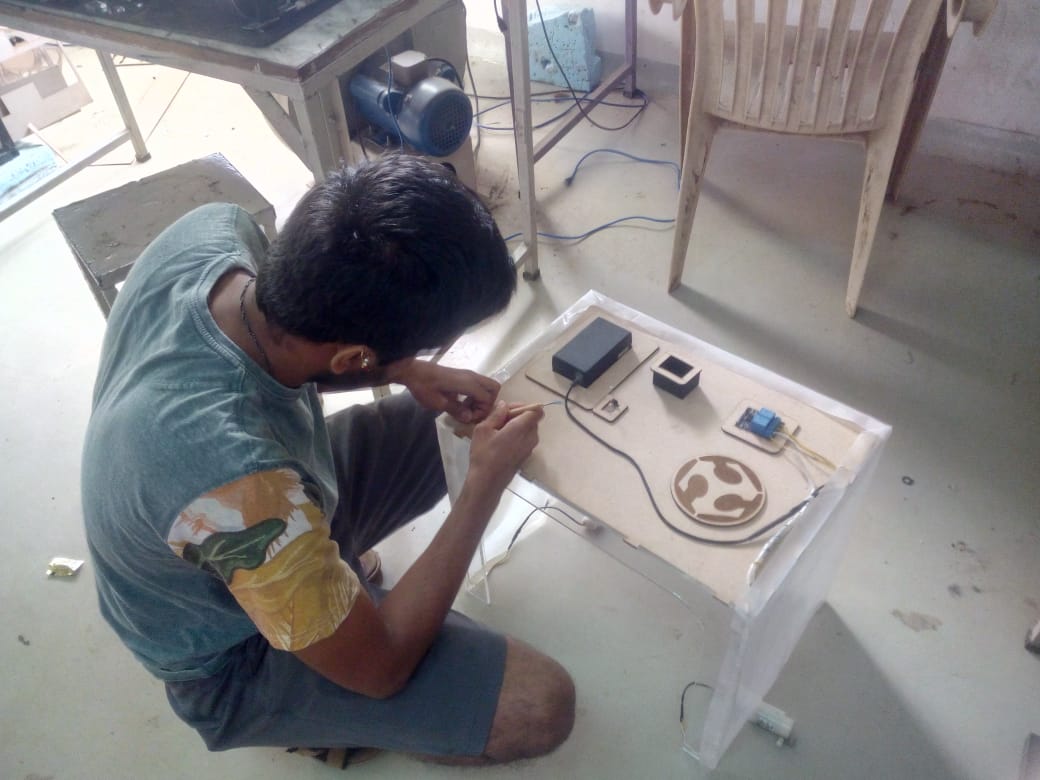
I made small rectangles to hold the PCB in place, then I taped the wires, the circuits and the 3D printed controller holder (design linked here and here) to the MDF sheet.
I've rewired the circuit after comments from the evaluator, scroll to the update part of the page to see it.
The next step is programming:
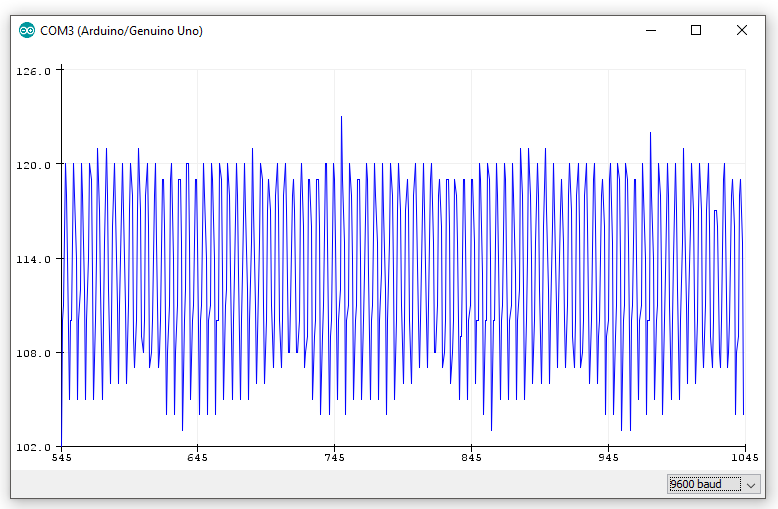
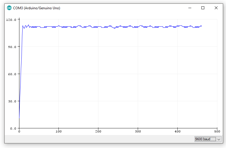
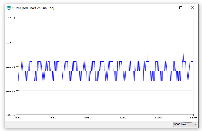
I'm using LDR for as input.
Testing the output of LDR
The output is not very stable..
This is not very much useful.
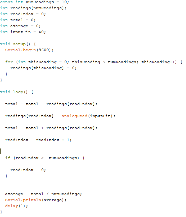
Hence I went online and browsed the arduino playground for some smoothing
The program for smoothing is available here
Here I'm taking the input in an array, then calculating the average of all the values in the array.
I used this with LDR to control the motor as follows: My final code is below
The precompiled hex file of the above program is available here.
The schematic and board file is available is from my previous assignment, here
I've rewired the circuit after comments from the evaluator, scroll to the update part of the page to see it.
Mechanical System:
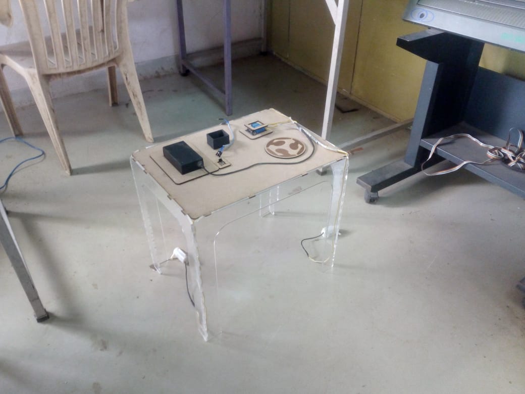
I designed a lasercut structure in solidworks. I used 5mm acrylic. I made a structure from it.
I made the top of my structure from high density MDF because, its cheaper and as the top part is not load bearing.
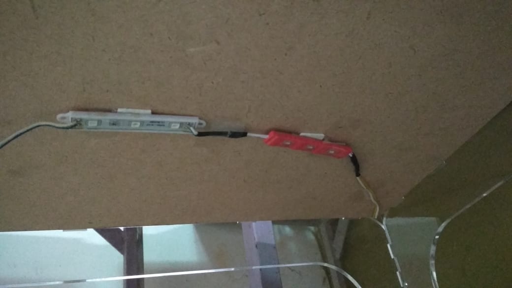
Then I stuck the LEDs to the underside of the MDF.
Then I assembled the electronics on the top of the circuit
After mounting the electronics I found that, the structure was not durable.
I used to come apart if I overcame the static friction between the pressfit joints.
I poured cyanoacrylate (acrylic glue) in the joints so that my structure will not easily.
I then stuck all the electronics on the top of the top, once I believed that it would not fall.
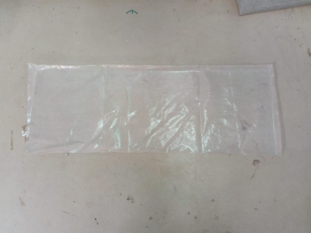
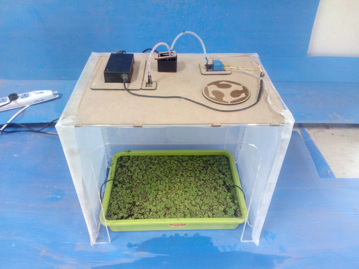
Next part was to create a hot enough environment for growth of azolla.
I went to the junkyard and searched for plastic paper, I cleaned it with water and dried it.
I wrapped it around the whole box so that there will be an accelerated greenhouse effect in the box
After securing everything in place, I placed an azolla bed inside the box
Update:
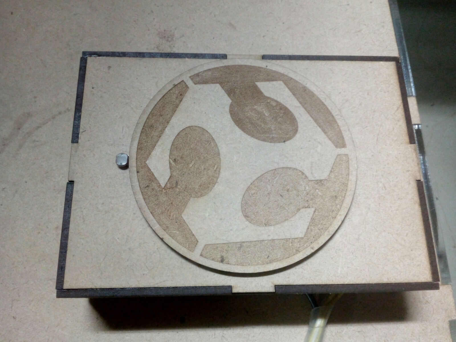
After some comments from the global instructor I decided to make a box casing for my project.
It will hide away all the electronics and make the whole thing nice and integrated.
I sleeved them with plastic sleeves.
I grouped together all the electronics, rather than spreading them.
I used 3M tape to stick the everything on the base again, except the LDR, so that it does not move.
Then calculated the approx dimensions of the box required to cover it all.
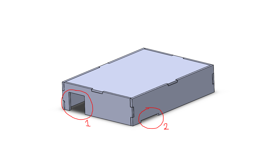
I the estimated the location for placing the wires, made slots accordingly.
There are two holes on the box
1: For attaching the main power source.
2: For the output of the relay, controlling motors, and LED
I'm using a LDR to turn on the lights, (i.e they will turn on if there is darkness.)
If I enclose everything inside the box, the LDR wont work.
I need to get the light on the LDR.
I wasn't able to determine the position of the holes accurately.
So, instead of making a hole in the design. I used 1mm drill bit (PCB drill) make two small holes.
I passed the LDR terminals through these holes
Once I was happy with the my stuff, I covered everything with my box
This will protect my circuits from the environmental dangers in the lab(laughable I know), but anyways I made it.
While designing the box it is important that all the stuff can be taken apart when needed.
For this reason, Ive used press fit components but only on the two sides of the project.
The top can pop up if enough pressure is applied.
Previous Work:
Karan Hardway from Lorain County Community College
Plastic trays 2 (one in box, one for harvesting): 60rs
Light Dependent Resistor: 10rs
Water Pumps 2: 400rs
MDF sheets (1 nos.): 30rs
ATtiny 45: 80rs
DC power adapter 12V: 70rs
Red LEDs (1 nos): 50rs
Blue LEDs (1 nos): 50rs
Total: 750rs
Bill of materials for future plan:
Plastic Trays: 60 * 20 = 1200RS
LDR 1: 10RS
Water Pumps: 8 * 200 = 1600RS
MDF Sheets: 30RS
ATtiny 45: 80 * 1 = 160RS
LEDs: 250RS
Total: 2900RS
License Info:
I have chosen Apache License for my project.
I have chosen this in the spirit of open source development, and entrepreneurship development
More reasoning behind this can be found here
Processes and purpose:
1: 2D Design: Used 2D design software to prepare a housing in acryllic, also designed a box for housing the electronics.
2: 3D Design: Used to design box (later to be 3D printed) in Antimony.
3: laser cutting: (Subtractive manufacturing), Used to create the housing but cutting the design made before to acryllic and MDF, also used for creating a box for housing the electronics
4: 3D Printing: (additive manufacturing), Used 3D printing to 3D print a box for holding the main circuit board.
5: Electronics design: Used Eaglesoft to design a few board for my final project, which will hold LDR and the ATtiny 45 processor.
6: Electronics Production: Used Fab modules with modela MDX-20 machine to mill my board.
7: Micro controller Programming: I used Arduino IDE write code for the micro controller, As it is much easier to code than in C or embedded C.
Source files:
Finally, all the required files are available to download here.
Presentation Slide:
The image is actually 1920X1080, I have resized so that it will fit in the current page.
The full image can be seen here
Presentation Video:
The video is actually 1920X1080, I have resized so that it will fit in the current page.
The full video can be seen here