Rohan Rege
Fab Lab Zero
Vigyan Ashram
<- Home
This week we had group assignment, this may cause the same image to appear on pages of multiple students
This week were tasked with:
1: Group assignment:
Test the design rules for your 3D printer(s)
2: Individual assignment:
- 3D scan an object (and optionally print it).
- Design and 3D print an object (small, few cm) that could not be made subtractively
Machining:
Machining is any of various processes in which a piece of raw material is cut into a desired final shape and size by a controlled material-removal process. The many processes that have this common theme, controlled material removal, are today collectively known as subtractive manufacturing, in distinction from processes of controlled material addition, which are known as additive manufacturing.
Subtractive manufacturing is more common and more faster than additive manufacturing. There are many processes like drilling, milling, turning, facing, etching ... but in additive manufacturing there is only one process '3D printing'
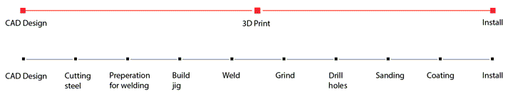
3D printing has its own advantages and disadvantages but the one I liked the most is single step manufacture. Additive manufacturing machines complete a build in one step, with no interaction from the machine operator during the build phase. As soon as the CAD design is finalized, it can be uploaded to the machine and printed in one step in a couple of hours.
Other equally important benefits include-
- Low cost
- Speed
- Risk Mitigation
- Design freedom
- Better Sustainability
3D Scanning
For 3D scanning we have the 'Sense 3D Scanner' it is the one of the most easy to use and handy scanner.

You simply point the scanner at the the object to scan and start moving the object or move the camera such that you cover almost all sides of the object.
The specs of the scanner are as follows.
Scan Volume:
0.2m x 0.2m 0.2m (min) (Lower the better)
2m x 2m x 2m (max) (Higher the better)
Depth Resolution at 0.5m:
1mm
Spatial X/Y resolution at 0.5m:
0.9mm
The scanner only works with the provided propriety software provided by 3d systems. Using the software is simple. To start scanning install the software, then activate the scanner by providing the required details.
For the first time, I scanned tried scanning my colleagues Rutvij and Kamlesh. For Rutvij, he was stationary and I was moving the scanner manually around him. This proved harder that expected. Keeping the scanner stable moving around the subject and looking in the laptop to verify the output was tough.
My first attempt:
I did mess up due to uneven scanning, the scan was useless, you could make out the details but the total CAD was distorted. To overcome this, for Kamlesh, I fixed the scanner on a tripod and used a rotary chair to rotate the subject. I also a used a white-board in the background to block all unnecessary things. Every time Kamlesh rotated at around 90deg the scanner used to lose tracking. I tried reducing the speed of the rotations to help capture better images. I had no success.
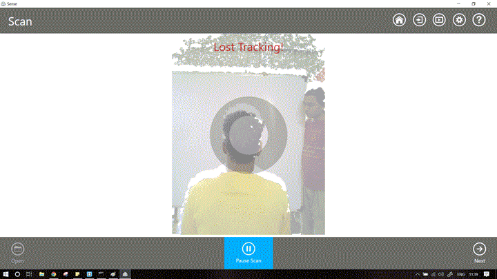
It was annoying and totally unacceptable. I decided to take a break and browse the internet. I just googled Sense 3d scanner and decided to look at some amazon reviews. Oh boy!
Possible problems are-
- Kamlesh is fairer and his skin tone is close to that of the background
- Kamlesh has a unique hair profile, this might cause problems with the scanning
- Kamlesh had wore a yellow shirt which was reflected more easily on the shiny background.
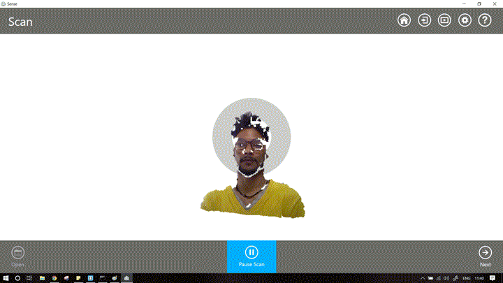
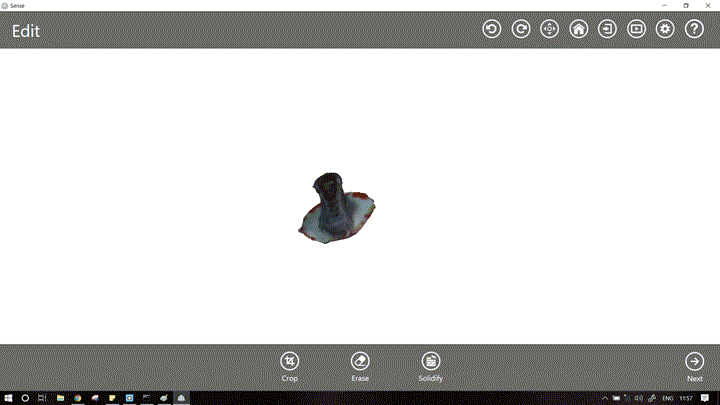
I decided to change the subject. At that time only Rutvij, Kamlesh and I were in the lab. I decided to scan myself. Rutvij held the scanner. This time the scanning worked good.
Here is a scan of me!!
The files are available to download here
Maybe the stability of the hand plays an important part in the working of the scanner. After 2-3 tries, I got the hang of it. Correct lighting plays a major role for proper scanning. Personally, I found it easier to scan the subject by holding the scanner in hand rather than mounting it on a platform and rotating the subjects.
If the subject is reflective (eg glass, mirrors..) , it will not be scanned properly.
I decided to scan my shoe, it is dark, non reflective. I set it on a small stool.
Select Object -> Small Object
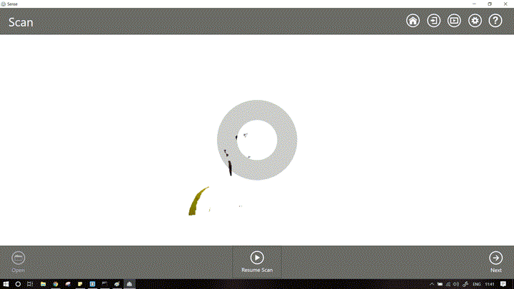
Now move the scanner back and forth until a small green square appears on the object. This indicates that the scanner is able to recognize the subject. Sometimes (many times), the square will not appear, don't worry. If you can see your subject properly start scanning.
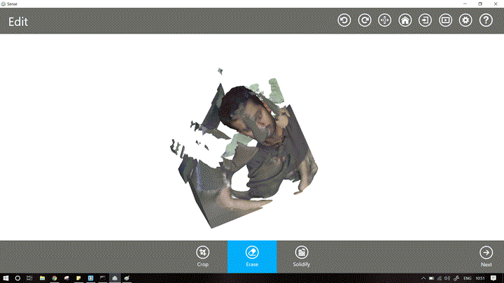
When you are satisfied that you have captured the geometry from all the directions (all the 3 axis, XY and Z).
Pause Scanning -> Next -> Erase unneeded artifacts -> Solidify -> Save file
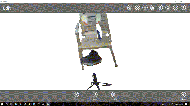
One thing I noticed was that, If I selected to scan "object" lots of background artifacts come into play, e.g. chair,table, legs of turn table etc... But when I selected the scan persons, There are no other objects. I wonder how much training it had to go to differentiate humans from objects.
The thing I wanted to scan was a desk. There is an option in the sense to scan upto 6 feet (very large objects). I also wanted to see if it could capture both humans and objects in in the object settings. Scanning the matte objects like tables is easy, the challenge was to scan the laptop displays and monitors. The initial trial failed, due to human error. Ugyen who was supposed to sit still, moved and the scanner got upset. The next scan was pretty good.
I have uploaded the file to sketchfab.
The files are available to download here
The next logical step after creating/scanning myself was printing it.
3D printing
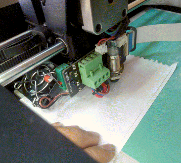
In Vigyan Ashram we are using the Julia 3D printer by Frakralworks.
The build volume is 210x250x260 mm3, the required filament size is 1.75mm
The supported filaments are ABS, PLA, Bronzefill, PHA and Ninja-flex additionally XT-Copolymer, Carbon-Fiber and Nylon are supported with a different nozzle.
The dimensional accuracy in XY is 20-100 microns while that in Z is 20-50 microns.
The printer software supports both .stl and .obj files. Both, direct interface via USB or Secure Digital cards can be used.
The first task is to characterize the 3D printer.
The most common tests include, orientation, infill, quality, overhang, wall thickness, hole test....
For orientation, we chose a small L shaped block. It was placed in different orientations.The objects were sliced together
The gcode for is available here.
They were then sliced via the software, and the output gcode was then stored on the SDcard.
Printing the file on Julia is relatively simple, Just apply enough glue to the bed. Then select the file you want to print from sdcard and click print.
The total time required for printing was around 45mins.

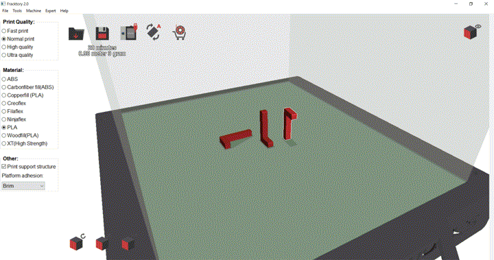
The next we performed was the quality test. Gcode for Julia is made by Frackory software, The interface is rather simple.
We can only control a few things like quality, material, type of bed adhesion and whether supports are on or off.
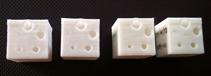
This is good for newbies but some of these settings keep lots of things ambiguous. So test these settings I decided to perform a custom test. I created a simple 20mm cube. With some patterns on it. On the top, it has 81 holes of diameter of 1.5mm. On left face it has 3 holes diagonally placed with increasing diameters. On the right side there are 6 holes again with increasing diameters and with fillet on one hole. I then used the same model created 4 gcodes each exactly similar but with different quality of print. The fast print took just 30mins while the ultra print took almost 2 hours.
The model is available here
The gcodes for all the settings are available here
This test gave me a better idea on how to design my 3d model and which settings to use.
upon inspecting the top surface, we can see that only the print in ultra quality is acceptable. While that of fast has small holes between it.
On the side, there were 6 holes with increasing diameters and fillet to the central hole.
The central hole has a diamater of 0.5mm while the outside go on increasing till 5mm.
As seen, the high and ultra quality prints are acceptable in this case. The rest of the prints don't have fillet. Also the inside hole is not perfectly circular in those cases.
Also there some problem with the top hole in all of the cases, So it should be avoided.
Taking all this information in mind, I decided to make '3D print' something for my Fablab. The best place to get inspiration is thingiverse. I browsed some featured items and some in gadget category. One thing caught my eye.
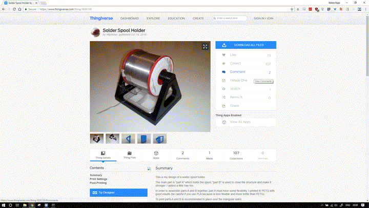
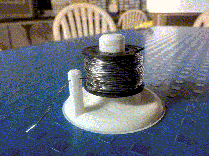
It is a spool holder for solder wire. I liked the idea, I downloaded the 3d model and opened it in Fracktory, the time required to print it was ~3hours. So I decided to make something similar, but my aim was to design in such a way that:- Takes less time to print.
- Uses less material
- Can be printed even on the lowest settings
- Removal of spool should be easy and single step process.
I took the dimensions of spools we have in Ashram. They are 80mm in height and 50mm in diameter. Here where my first problem lies. The time required to print anything increases as we increase the size (common logic). To overcome this I decided to print in the lowest quality. From my tests above, for lowest quality, the minimum hole diameter for a good quality hole is ~2mm. As a task was that the object cannot be made by machining My hole for solder wire is not straight, it actually curves inside the column. So to be safe I went with a hole of 3mm diameter.
The next thing I did so that it cannot be manufactured subtractively is I made the insides hollow with a wall thickness of 1.7mm. This hopefully also reduce the print time.
The files are available to download here. Includes the SW (editable) as well as STL file.
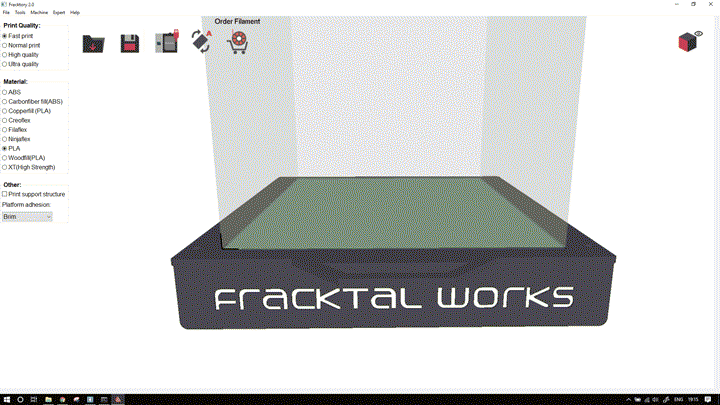
To print the file:- Click the load button
- Select the stl file
- Select the support structure
- Select the material
- Select the platform adhesion
- Select if you want supports
- Click the floppy icon to save the gcode.
- Now put the file in SD card and insert the SDcard in printer.
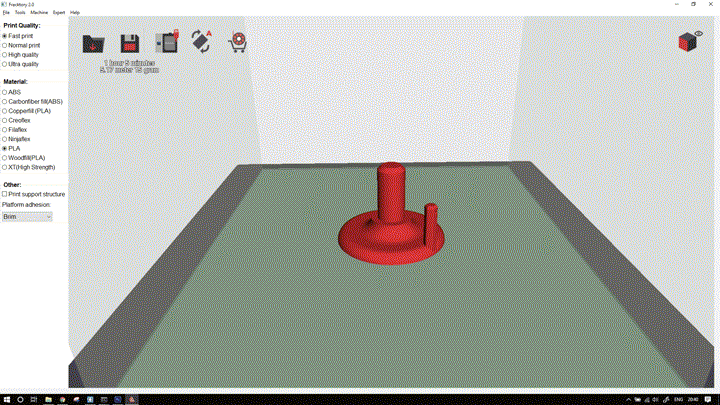
Also note my file just takes ~1 hr to print.
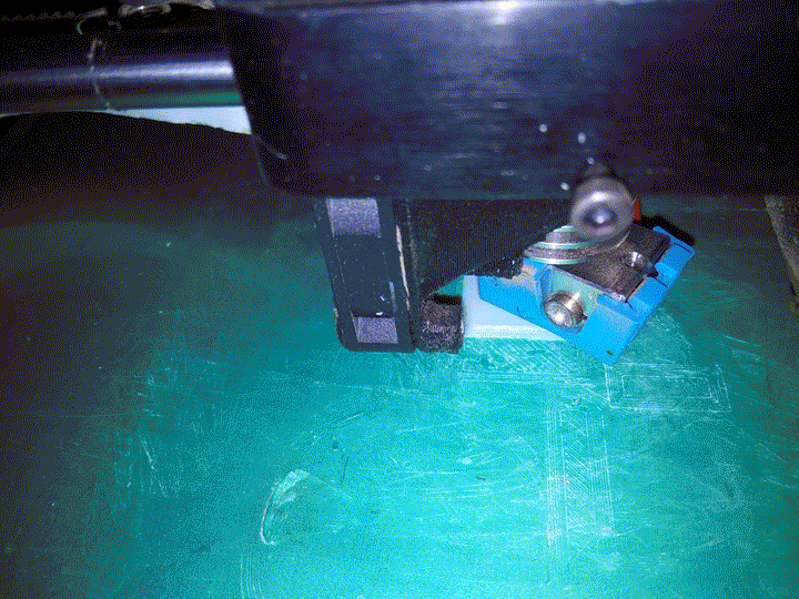
In printer, apply glue to the bed and select the file you want to print.
Sometimes bed alignment might be necessary, to do this,- Control
- Auto bed level
- Follow the steps on screen
- The printer will take care of he rest!
After leveling select your file and the printer will do the rest.
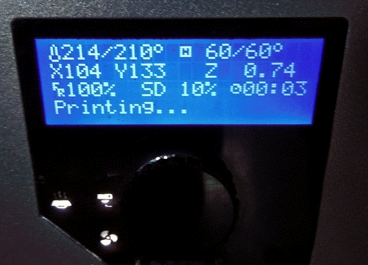
Julia takes care of bed temperature, nozzle temperature by itself.
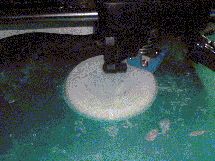
Looks like there is some problem.
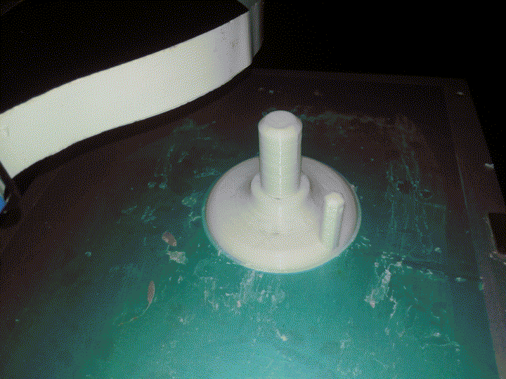
False alarm, It was meant to print like that.
The print is rough around the edges, but it is functional. It is surprisingly rigid for a hollow print.
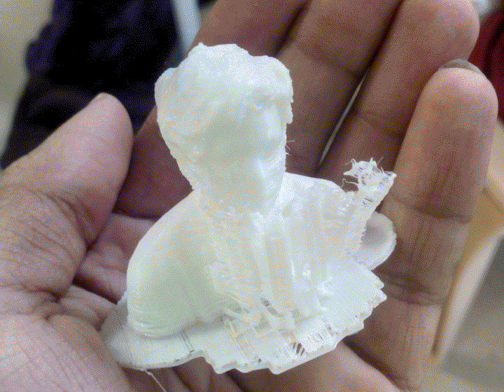
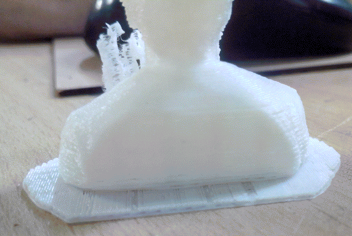
For bonus, I even printed the scan of myself which I created earlier.
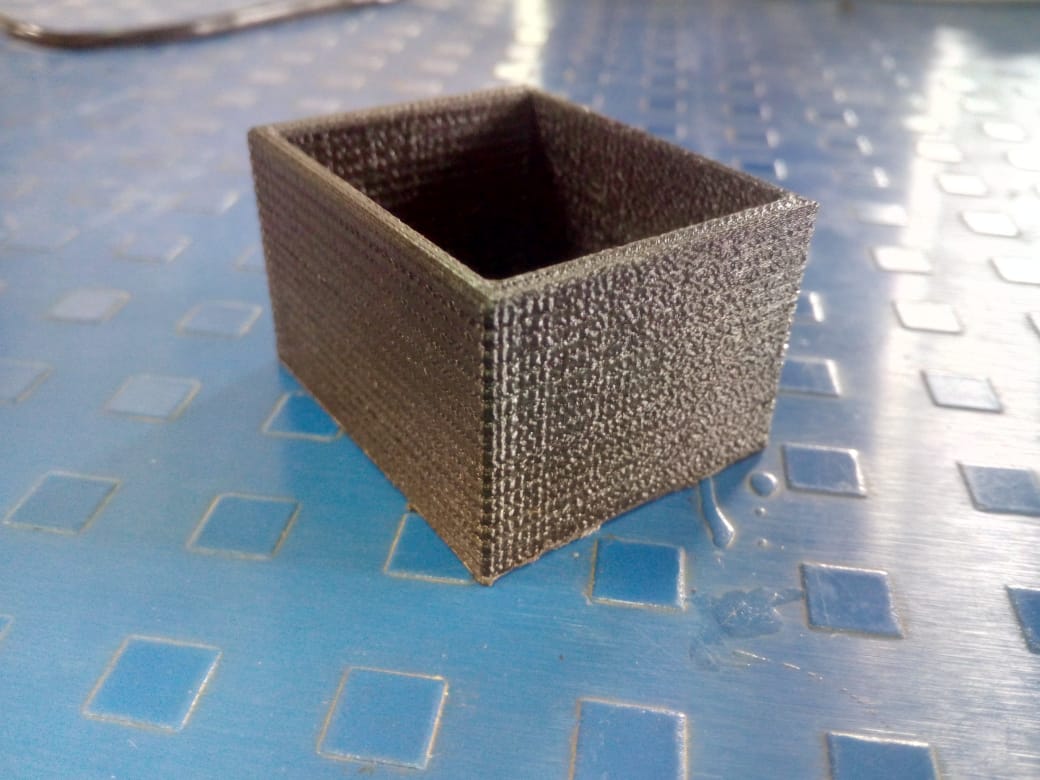
For my final project, I needed a box for my electronics circuit.
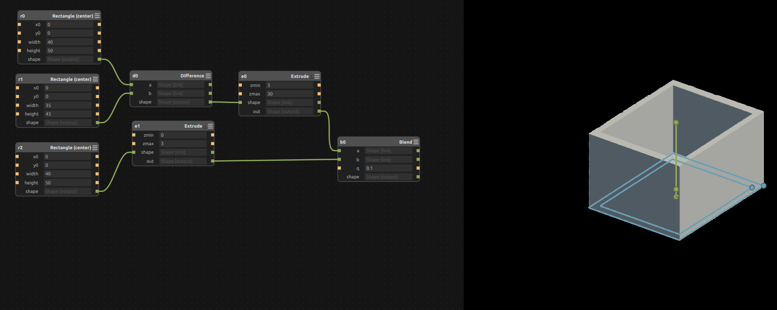
I had designed this box, in antimony you can find the details here.
I 3D printed the box by generating the STL file.
The STL file can be found here
The gcode can be found here