Rohan Rege
Fab Lab Zero
Vigyan Ashram
<- Home
This week were tasked with:
1: Group assignment:
- design a machine that includes mechanism+actuation+automation
- build the mechanical parts and operate it manually
- document the group project and your individual contribution
Machine weeks are finally here.
This year the team at Vigyan Ashram decided to work on a robotic arm.
")
A typical robotic arm is built with fixed length segments that are connected either at joints whose angles can be controlled, or along linear slides whose length can be controlled. If each angle and slide distance is known, the position and orientation of the end of the robot arm relative to the base can be computed with the simple trigonometry in robot control.
Later we will find that the simple simple trigonometry is not so simple.
There are only two engineers (me and Rutvij) this year.
The Whole team decided to decided to work in two parts
- Mechanical Engineering
- Electronics Engineering
I being the sole mechanical engineer was put in the Mechanical part
Arm is more of a electronics project than a mechanical project.
My task seemed pretty simple, To calculate the torques and various motors and decide the working mechanism and fabricate it.
The hard part is to make sure everyone who is hasn't studied mechanical engineering also understands whats going on and it works
Initially we decided to make a simple arm, no complex mechanisms, a stepper/servo motor at each joint.
This would be very easy for everyone and seemed doable.
We have made a special google doc file to collect resource, it can be viewved below
We decided to make the reach of the arm ~1m. (lol)
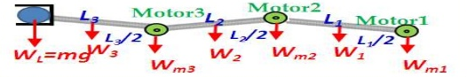
It can be confusing to find the torque on the motors, as when the arm moves the the torque value changes.
So we need to find maximum torque on the motor and then it will be safe for all other loads.
The formula to calculate torque is
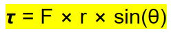
Where:
- τ: torque
- F: Force
- r: distance from axis
- θ: Angle between the axis
For τ to be maximum, all f,r and sin(θ) should be maximum.
Since F and r also constants, we need to keep sin(θ)maximum. Which is at π/2
The value of torque at this point is given be τ = F χ r
Hence the torque calculation is done as follows
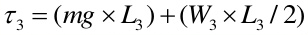

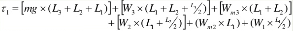
Me and Chaitanya did the initial calculations
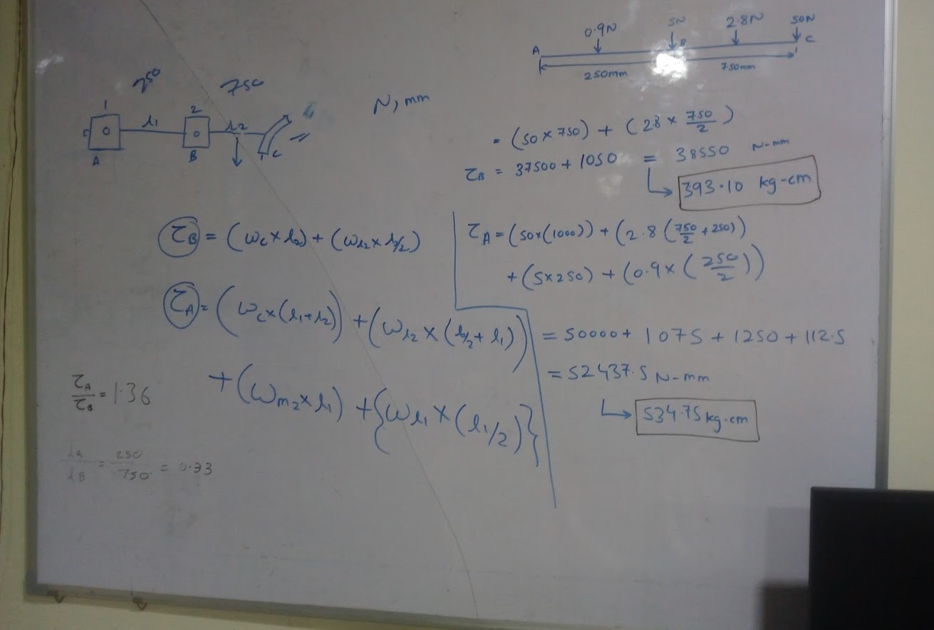
As you can see the torque is coming very high that is why, we decided to reduce the lengths of the arm.
we were playing with the arm lengths and it was very tedious for us.
Hence I decided to make a excel sheet.
It would have all the calculations of the arm.
The sheet helped our life by making calculations a breeze.
The sheet is embeded below and available to download here
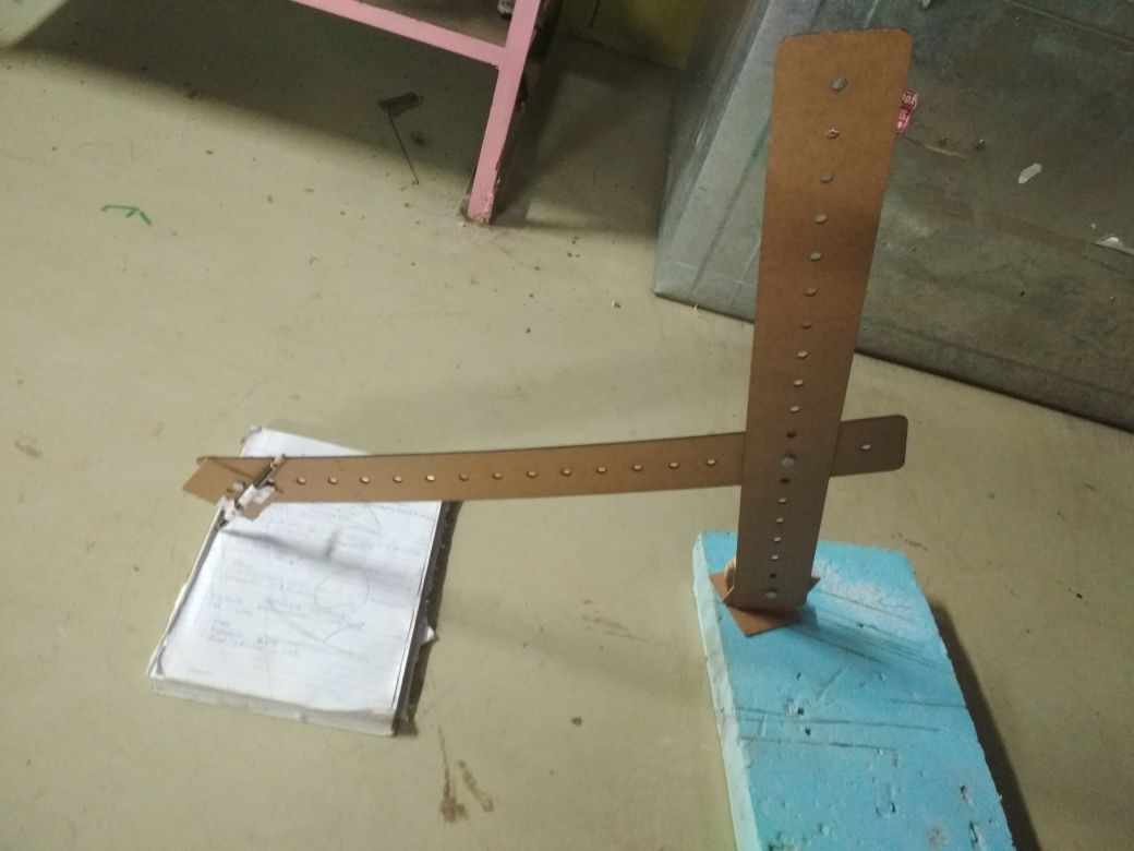
The next step was to find the reach for the arm.
The maximum reach and minimum reach of the arm will depend upon the angles between the two links.
To do this, I with the help of Komal made some DXF files with multiple holes, (as our arm lengths are not fixed).
After talking with Dr. Kulkarni we came to know that the budget of the arm is ₹3000. Which roughly translates to around €37.
We needed to rethink our strategy, hence I decided to to use a 4 bar chain mechanism.

Using a 4 bar chain as double crack mechanism, I could move one motor from the middle link to the base.
And use the link to transfer the motion.
This reduced a the torqure by a whole lot.
After some debate, we fixed the arm lengths to 350mm and 400mm
We chose these as they closely replicated the human arm.
And, as nature has evolved for so many years surely it must have chosen the right combination
We create the mechanism and finally lasercut the parts on Epilog laser.
We chose MDF for first prototype becasue there was plenty available.
The working mechanism can be seen in this video below
We later built the arm in acryllic, as it is more structually stable
The project page for this assignment is available here
All the Model files for the arm are available to download here