Aim:
To define and learn a manufacturing process
Task 1:
To decide and define the assignment to work upon
This week was a free will week, where we had to define our assignment and the standard of it.
For this the basic criteria was to have any task the includes digital fabrication of involvement of computer aided tasks, and should be other than the ones we had covered
For this we were initially defined and explained with a range of task, but we had free will to either choose between them or define any other one.
The basics were as shown here:-

Sub task:- Deciding my tasks.
Initially I had planned both composites and to work with robotics,for which I had also worked with the graphical interface using MIT app inventor in the Networking assignment.
After a few run throughs, I went through the machines in our sewing lab, one of which was a CNC operated embroidary machine, for which there could have been endless possibilities to work with.
Hence I decided to initially go with basic tasks, to learn the machine.
Task 2:
Learing and working with the machine.
Initially to know about the machine this was the one that we had,
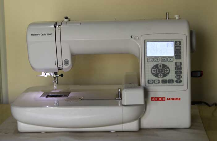
Ranging the specifications as follows:-
- Maximum embroidery size is 5 inch by 5 inch
- Built in 700 KB
- Machine has USB port for pendrive attachment or direct communication
- Software could be fed with raw inputs of JPG, BMP files
- Supports *.jef format
- Supports 650 SPM (stitches per minute)
- Supports work over a wide range of materials:-
- Leather
- Cotton
- And almost all synthetic cloths
- Supports a wide varriety of threads, including:- silk, cotton, nylon, rayon.
- The machine is capable to manufacture electronics using the conductive threads.
- etc..
The machine is operated by a machine software named as Digitizer, that bsically takes image formats and converts it to the file containing the path of operation. The basic process is explained below:-
The process
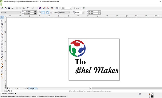
For the testing of the machine, I wanted to test something basic to see the working of the machine, where I decided to make the name tag for my final project.
For the same I did the basic cad design in corel draw, which was not a major task and exported it as *.jpg.
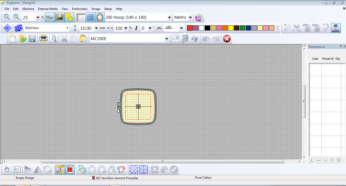
After that I loaded the design to the cam tool that could load up the path files for me.

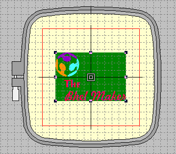
Here once opened the following interface was seen which basically displays the workable area of the machine(which can be manipulated according to need, for us it was pre-defined)
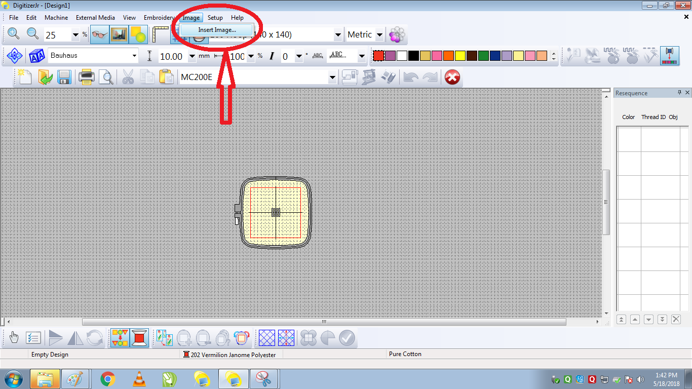
Once into the software you click image to import the JPG files you have created as your CAD designs, which appeares in the editable frame as seen here..
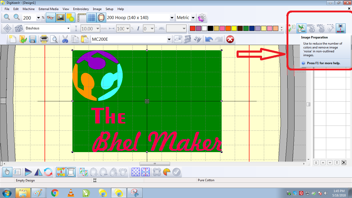
The next step is to generate the path file for the same, but before that there is a catch, the image that we generate is supposed to have multiple layers of colours.
If these are not seperated, the machine then increases the layers of material according to the layers of the colours(same as seen in laser cutter)
Hence we need to reduce the layers to bare minimum, for this the software has a provision namely "Auto colour Reduction", this basically as seen, directly seperates the layers of the colours, which intern helps for maintaining the number of passes.
After we have optimised the colour composition, the next step is to give the path, now unlike the other CNC router and machines that we used here we don't have to select the entire profile, or the edge to edge marking. Here we just select the parts of the image that have to be made out in various colours of threads.
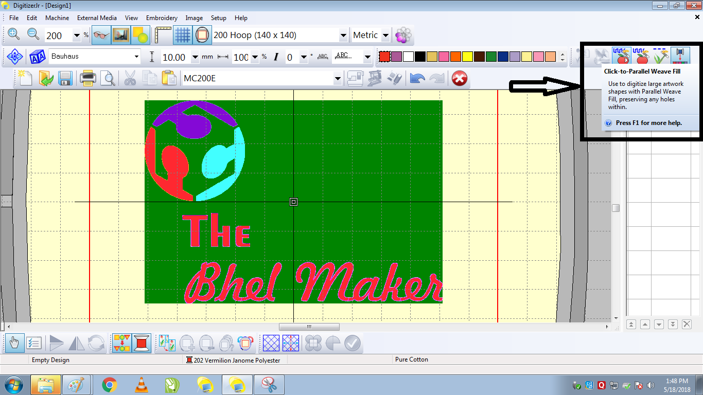
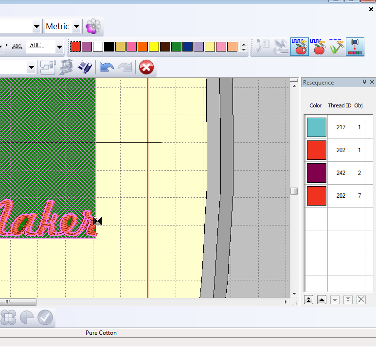
Basically the machine by default stops at the point where there is different colour of the thread chosen in order to provide a slot for changing the thread.
After which a simulation is given as in any CAM tooling

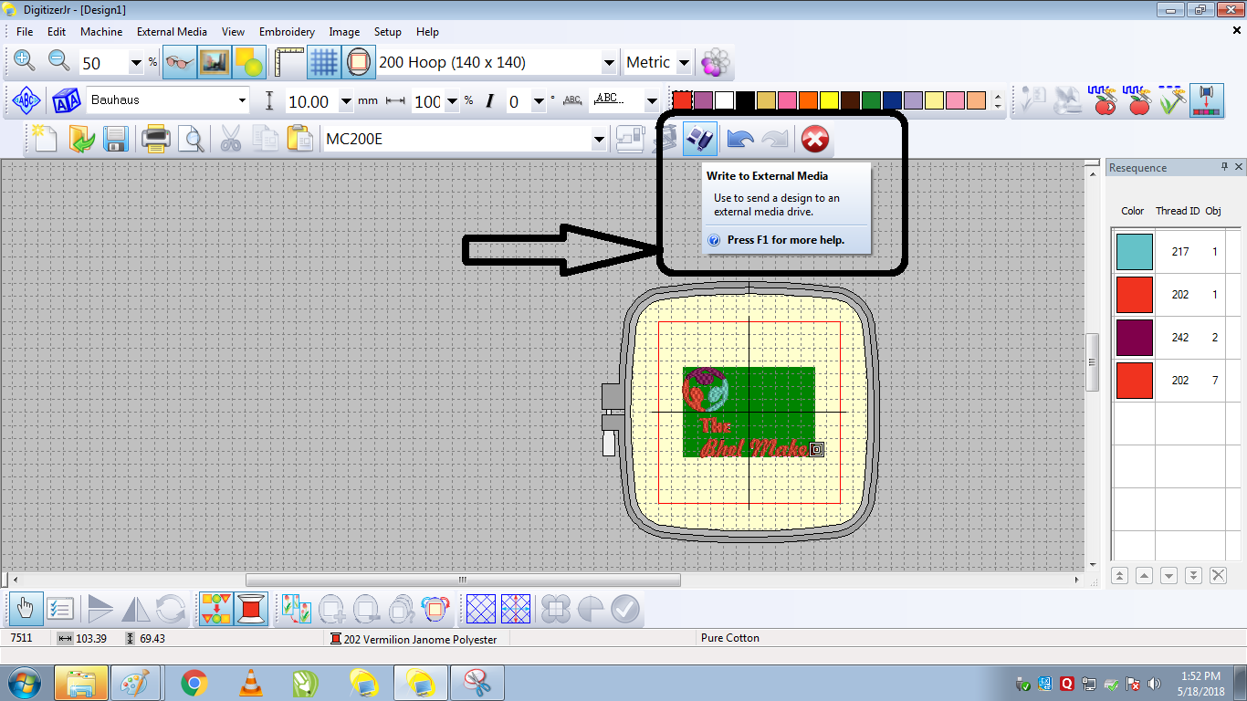
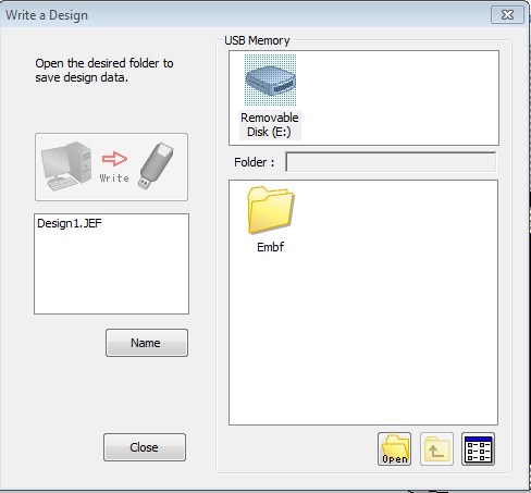
After once this is generated you hit the copy to device button, where the simulations are converted into a path(JEF file)
and then you send it to the machine.
Then on the machine you have this control panel where you pick and select the design(parts as you had divided in the CAM
tool),
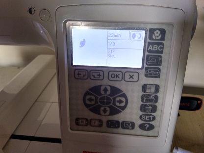
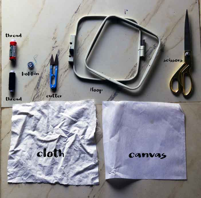
After which the thread has to be set(path is guided over the), after which we have to set the cloth,
For that the machine is provided with a hoop on which the cloth is attached, with a layer of canvas paper behind it
After this you sent the machine on...
After the job was done this was the final template I got for my machine..