Aim:
To study the modes of communication using various means
Task 1:
To unserstand the principles of communication.
The basic question this week was, how do these boards actually communicate??
Communication between boards is basically passing on the commands from one board to another.
For this we had two types of communications, that we were looking into, out of which this was something that I understood, out of both.
- Asynchronous:-
Asynchronous communication is the exchange of messages, such as among the hosts on a network or devices in a computer, by reading and responding as schedules permit rather than according to some clock that is synchronized for both the sender and receiver or in real time. It is usually used to describe communications in which data can be transmitted intermittently rather than in a steady stream.
Here real time means communicating simultanously..
The image below shows the difference between the types of communication...
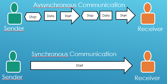
- Synchronous:-
In synchronous communications, the stream of data to be transferred is encoded as fluctuating voltage levels in one wire (the 'DATA'), and a periodic pulse of voltage on a separate wire (called the "CLOCK" or "STROBE") which tells the receiver "the current DATA bit is 'valid' at this moment in time".
It is generally used in the parallel communication..
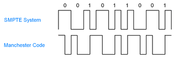
The following image shows communication between a single wire
Task 2:
Designing my boards for communication(asynchronous)
For this week we had to use two types of boards
1. A Bridge Board:- This board actually a board which communicates between the serial port and the other boards via FTDI, i
2. A node Board:- This is like a slave board which we connect to the bridge board to achive the communication
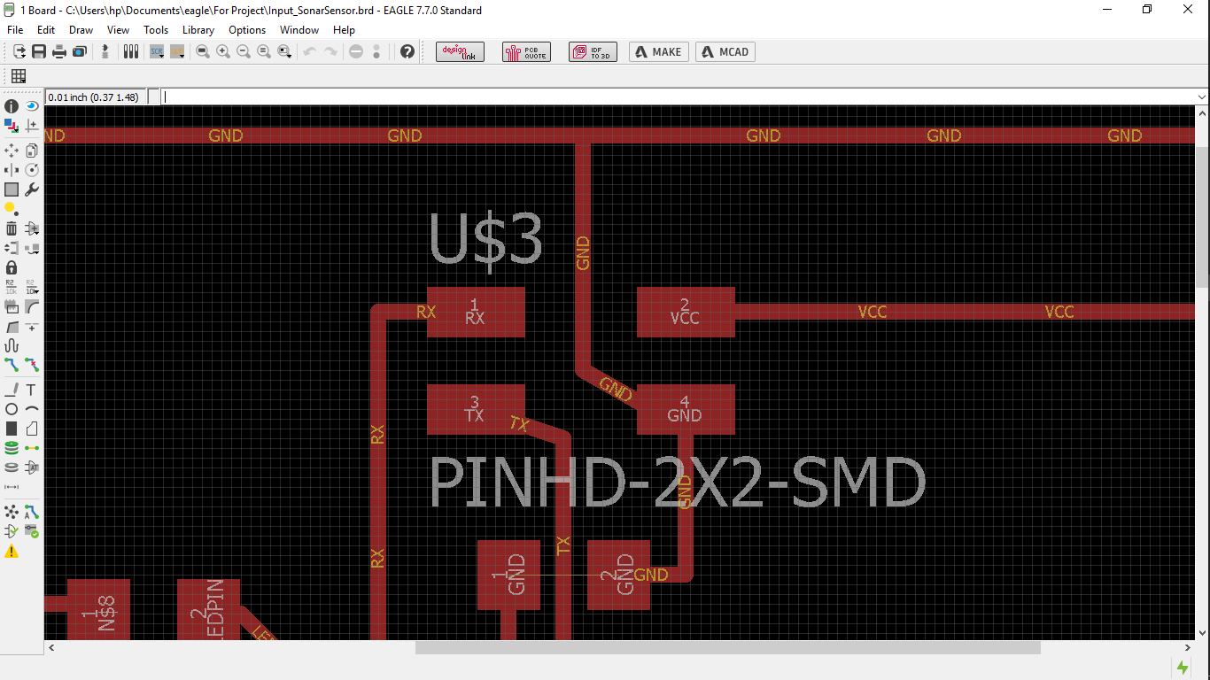
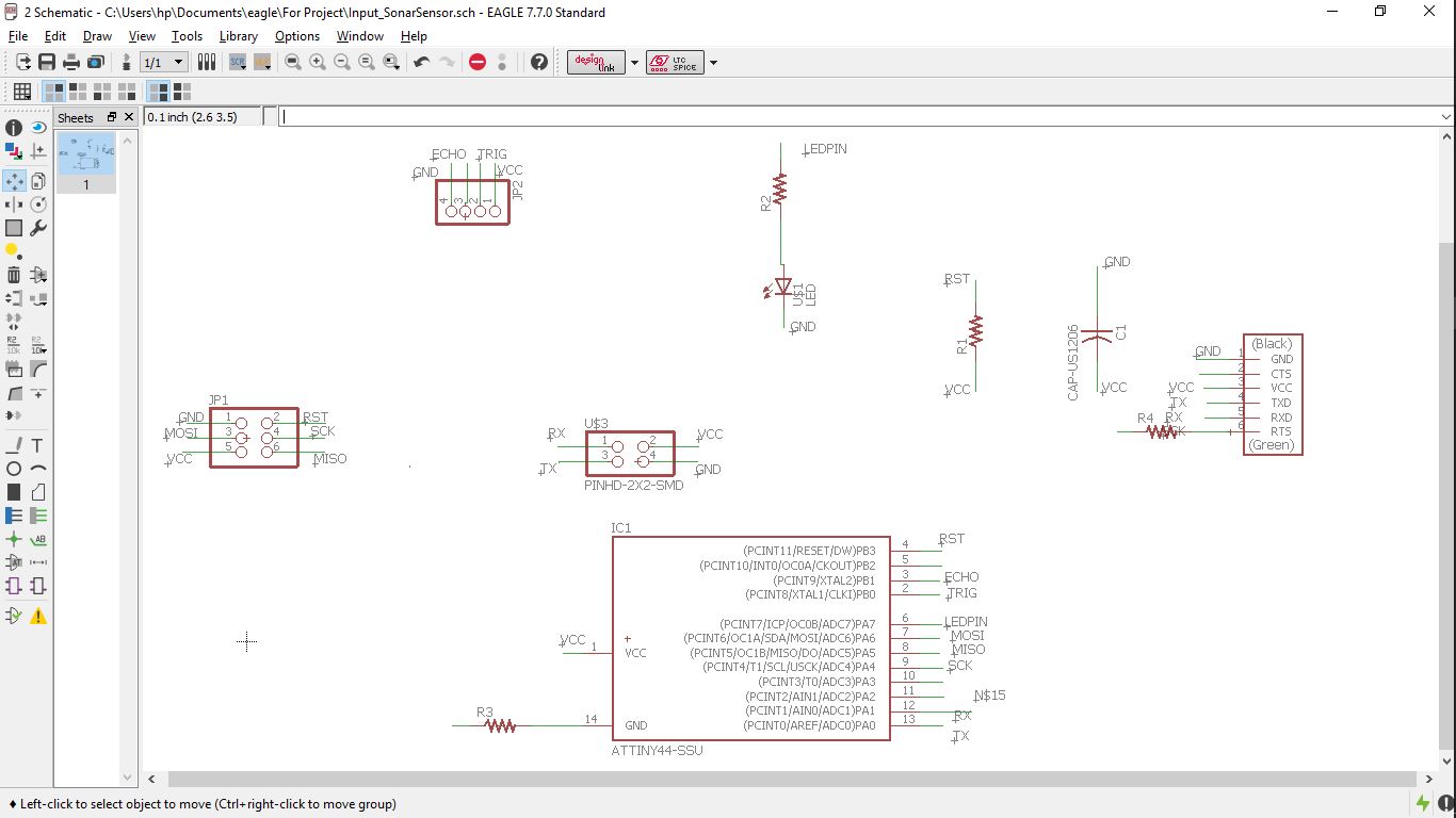
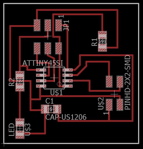
Hence considering the need I had designed my input board having both the FTDI and the communication pins..
After that I was planning to use my hello world and output boards, as nodes but had a few issue, as in my both of the boards the communication pins were lacking.
As a result I had to design another board as a node board.
For this I refered to the Neil's board as seen here..., which I tried to understand and develop a board of mine..
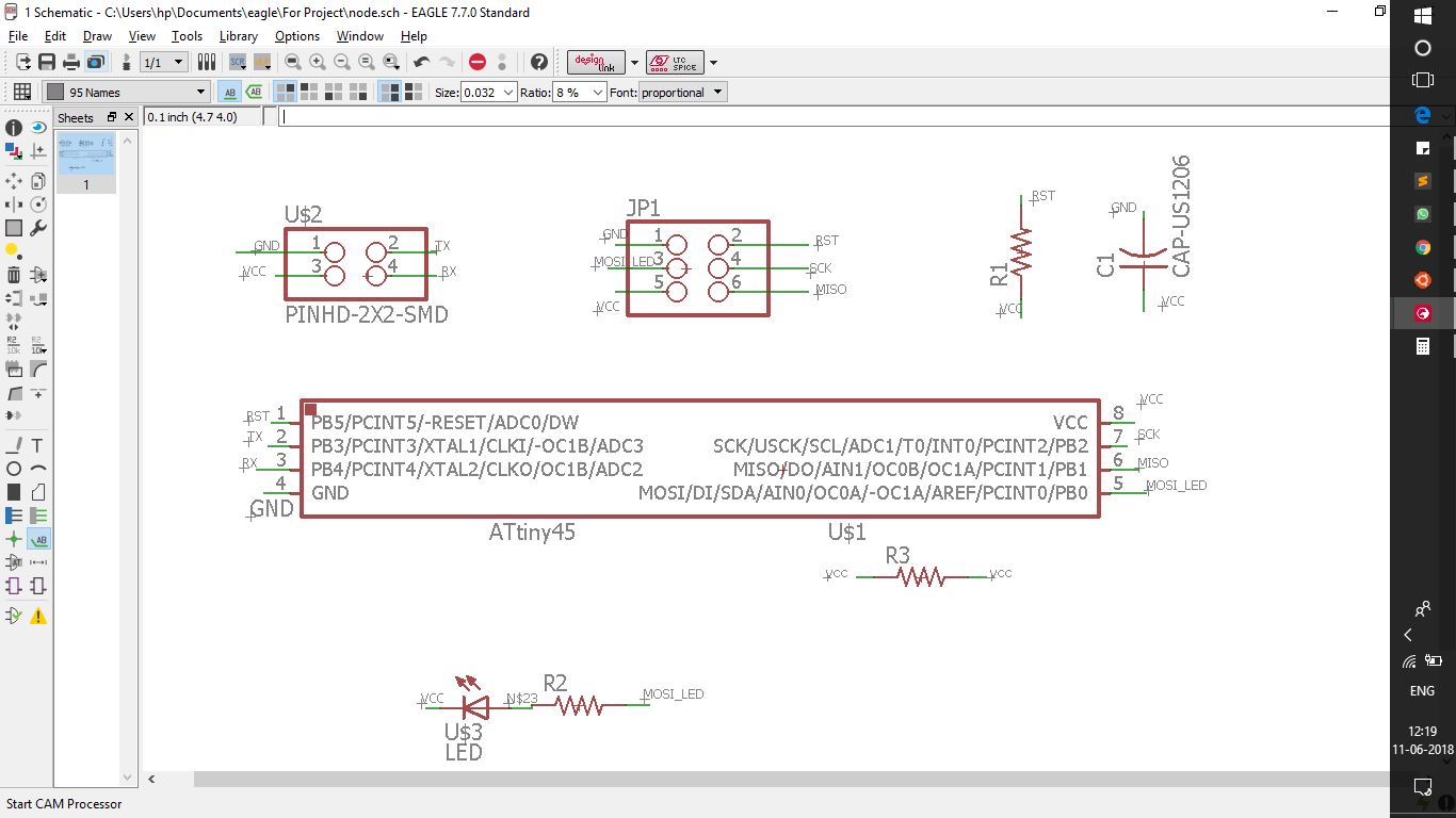
The next logical step was to manufacture the boards and then begin programming them...
Task 3:
Manufacturing and programming the boards
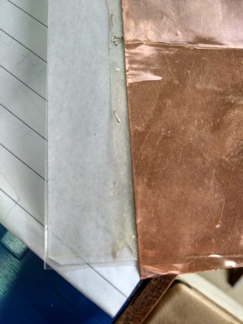
This was pretty simple task out of the past experience, this time we actually all wanted to try our hands on the flexible circuits.
For this we had to stick the role of copper sheet on to something rigid yet pretty flexible, for which we decided to go with the OHP sheet, and had fixed them up with a PCB tape, sandwitched between them...
Later this we fed to the vinyl cutter, and arranged the origin in and sent the print, the method has been described here
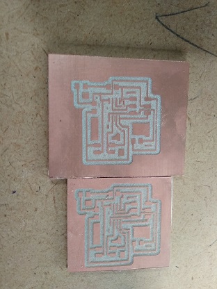
After which we got the following boards..
For this we had made a sheet of boards to ensure that we have enough to learn and scrap the waste,
The manufacturing on the vinyl was comparativly faster, I had cut a sheet of almost 8 boards in a span of 5 mins..
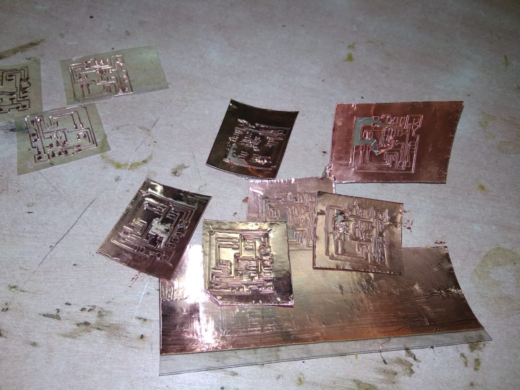
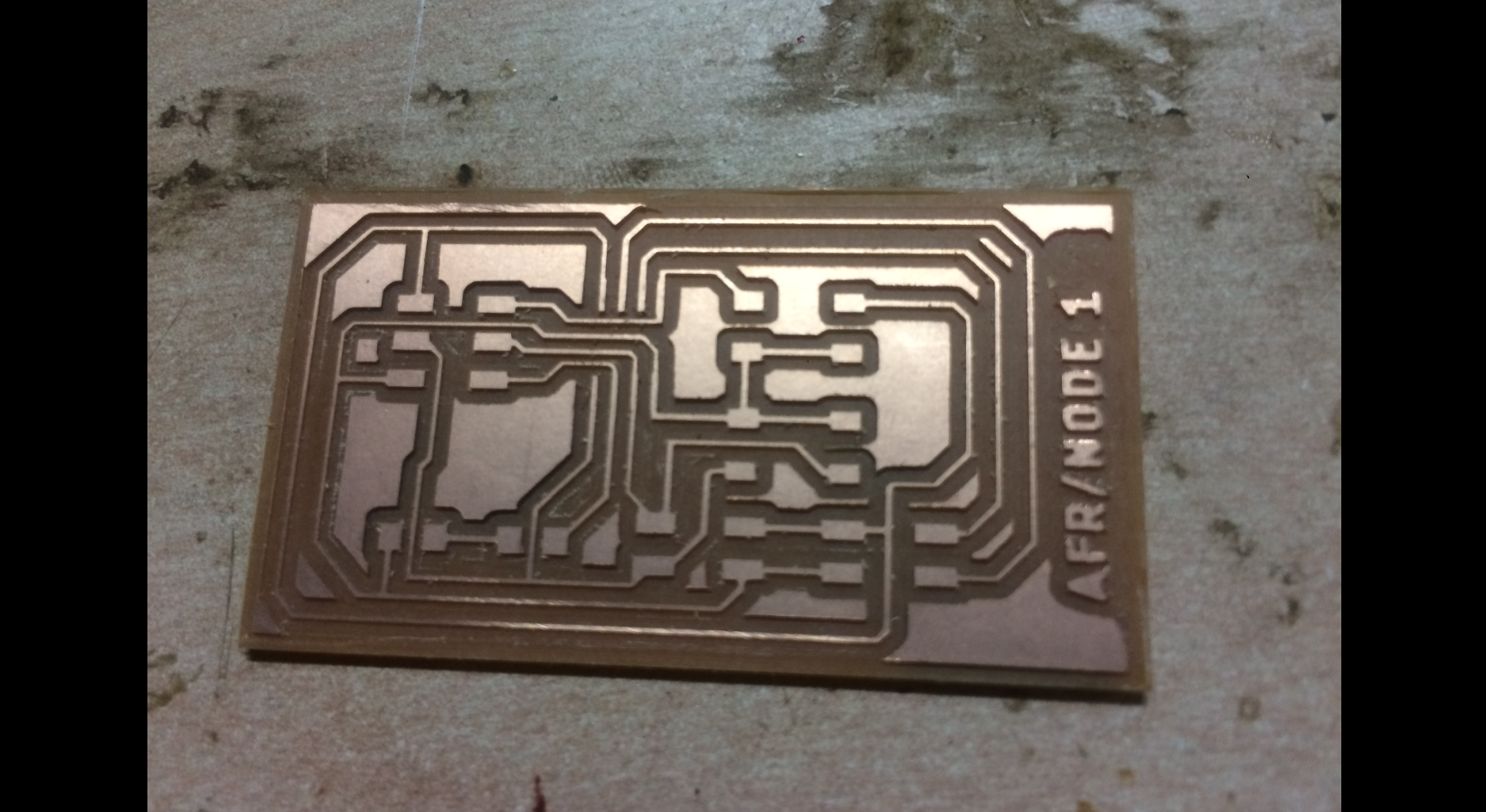
After this there was a task awaiting patience, it was to remove the excessive copper of the tracs, but this time it went quite well, than what I had done before for etching.
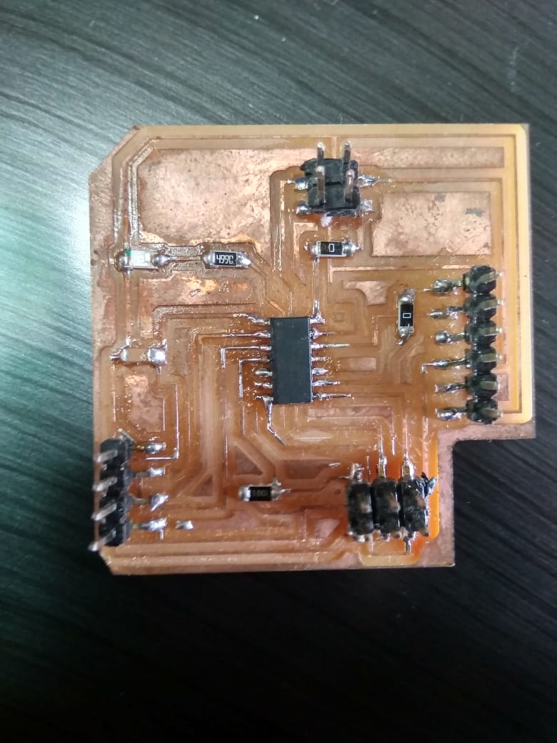
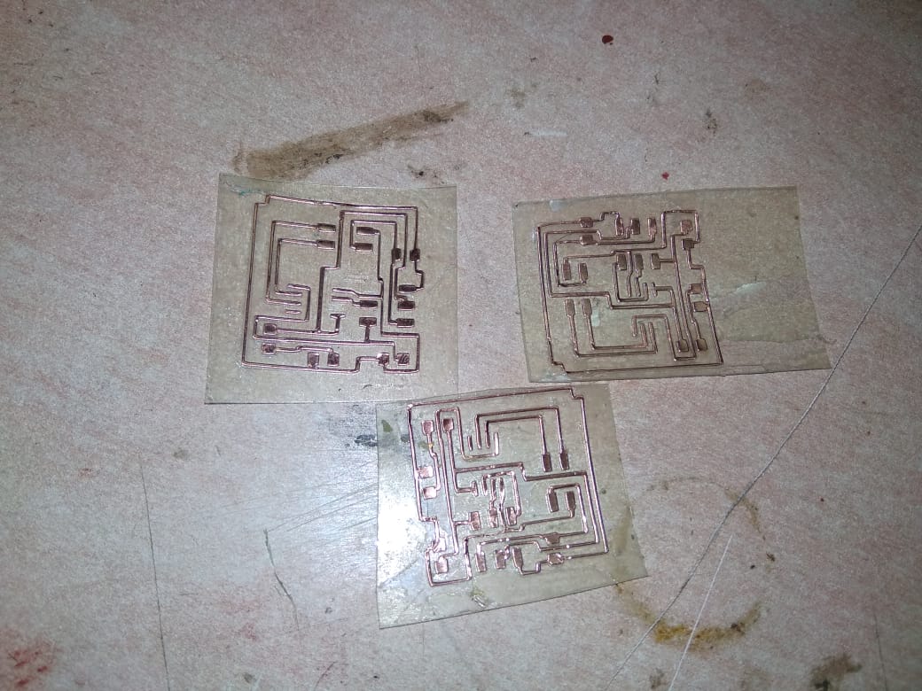
So finally I had got a board as seen here..
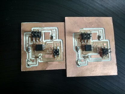
Which I had soldered but much of them were ripped off,
also there was an issue, when I sat for programming the board, I had the error about the device signature, which ment either I had to resolder the board or change the IC, this was a tedious task which I chose not to go with, cause that would have ripped my tracks up.
Hence I decided to avoid the rework and decided to mill the board.
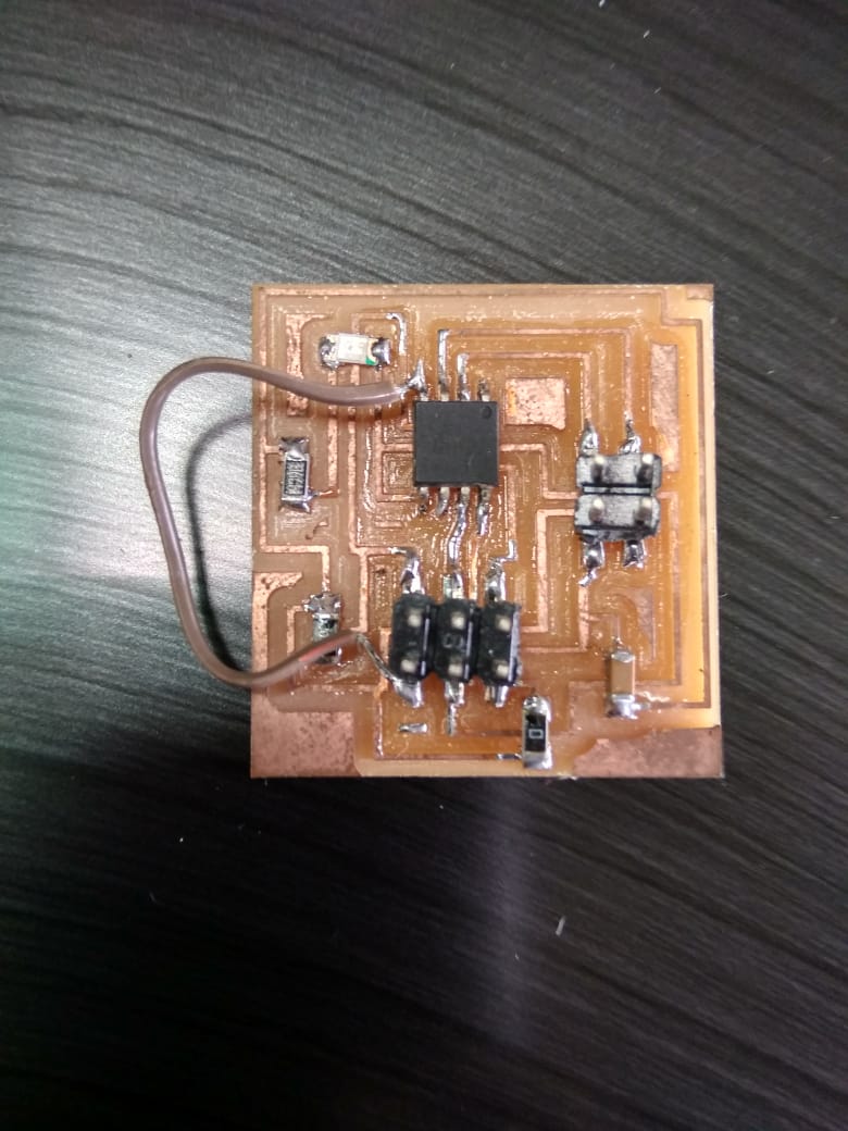
Milling the board.
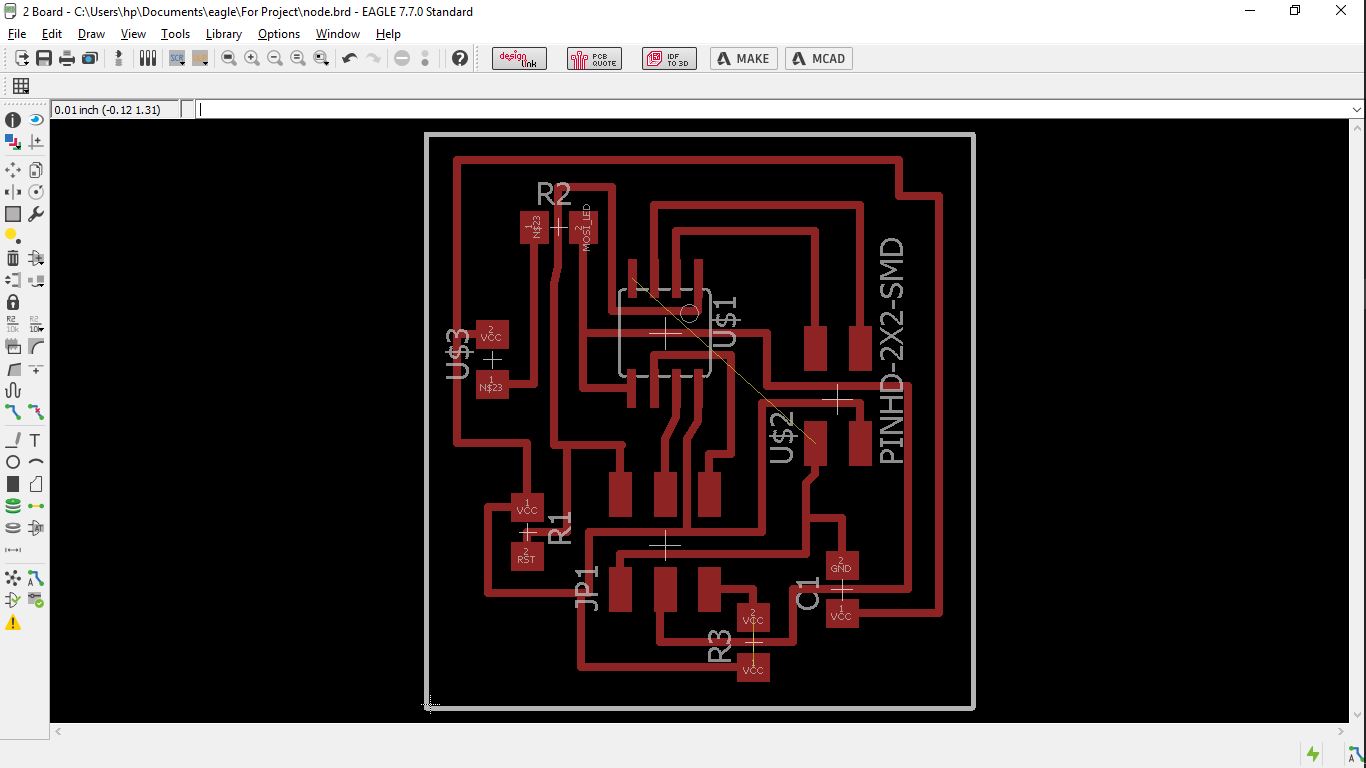
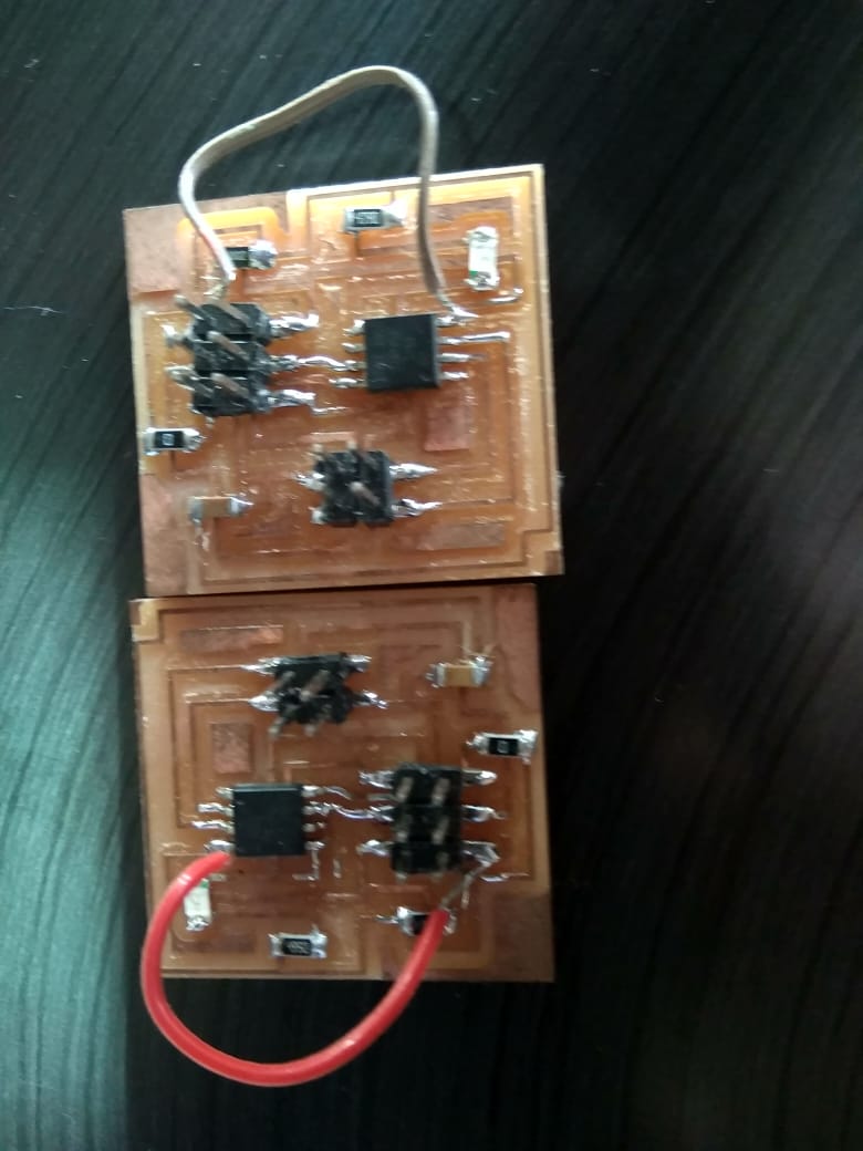
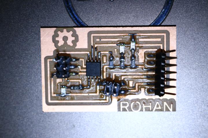
This went pretty simple again, I milled two of my node boards and soldered to get these one out.
This was considerably easy task, as we had worked with these previously..
Actually later after a few realisations I was bound to change the nodes, this was because of design errors, as the RX from the bridge goes into the TX of the nodes, and my initial board were opposite to this, and showed a need of jumper cables that would have made it shabby, hence I re designed the boards and got them milled and soldered.
Programming the boards method 1:-(asynchronous)
This task went pretty good than the ones experienced before, here I had decided to go clean, just work with Neil's code, to understand and change it to get respective results..
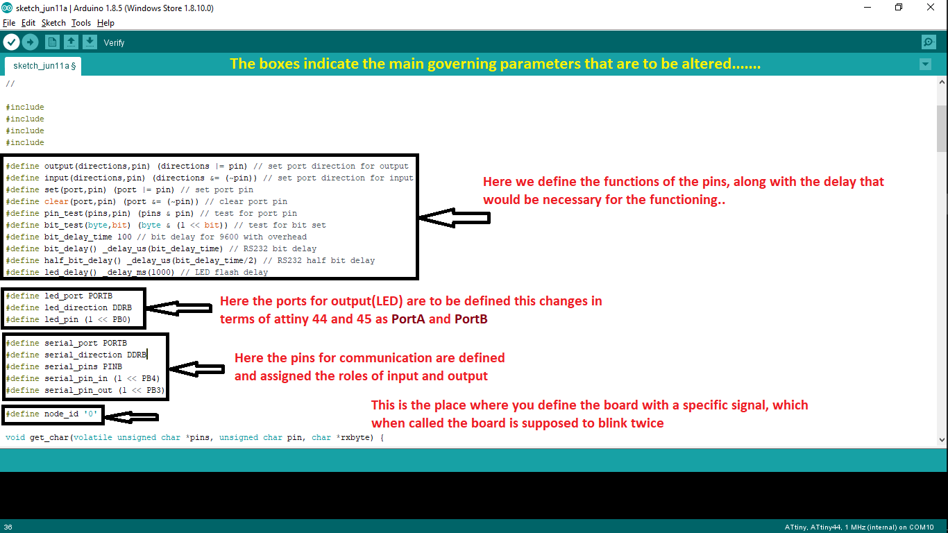
The major change here was only regarding the two different processors, those being Attiny44(in the bride board), for which I had edited Neil's programas seen below,
And edited the same program as following for the Attiny45(in the node boards)
The code basically functions as follows:-
Which when was ran on the board worked for the indiviudal ones as test codes..
After which the only thing left was to burn the programs on respective boards, and get them running no the setup seen below...
After which I got the following results..
Here when seen two leds are constant on since they are grounded with VCC hence they are constant "ON" and turn off, on the pulse, and rather for the bridge board it's grounded with GND, hence it is constant "OFF" and turn on, on the pulse.
Programming the boards method 2:-(asynchronous)
This actually was just a planned phase, I had not initially decided to go with this due to lack of time, but during eval I was suggested to work with another method other than neil's code, so for the same I decided to pull out the idea that I had,
The idea was simple, to get an input from a sensor, and let it communicate with the other boards according to the conditions specified.
For this I had planned to use the ultrasonic sensor of my input board(as the board was designed for the same), hence I went a code that was a lil modification to the ping, logic was something in the sketch..
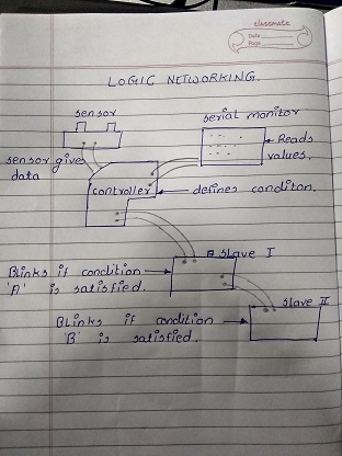
Hence I wrote a code succeding the Ping in the arduino library which was designed as explained..
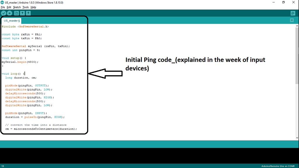
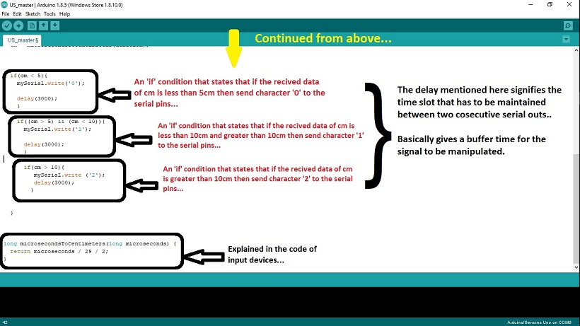
This was to burnt on the master board(the input sensor board)..
Later to communicate further more I had to brun a code on nodes, so I worte another code for the nodes that is explained as follows...
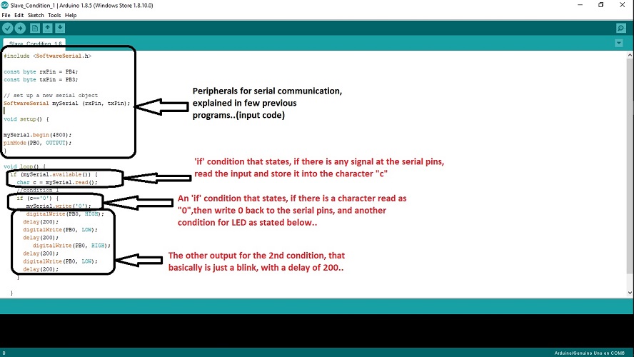
these were termed as slaves and there were two logics those were burnt which slaves, basically satisfying two individual conditions.
Hence I took a few trials on the boards, basically checking the output on the serial monitor, later I burnt the program on the respective boards, and then connected them as the figure shows..
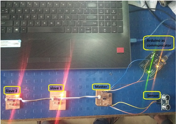
Here I had used the arduino for the serial communcation(to read the data on the serial monitor), since I had found our FTDI was not working properly.
Rest as the video shows.
Task 4:
Trying other methods of communication
This was one of the method I had just done for testings and not as a part of my assignment, since I was not using my board here, it was arduino. The methods and the reason for using arduino has been suggested in the assignment.
This was one that I had tried in the week of Developing Interfaces, I had generated an app that would control the back and forward rotation of a dc motor.
The entire communication here was through bluetooth where a bluetooth module was connected to the arduino that was supposed to recieve signnals from the app via bluetooth, this was one attempt to go with the wireless communication, which could be boardly seen in the video here...
The process of functioning and working has been defined in the assignment step by step
Task 5:
Group assignment
The case we wanted to try here was to communicate within boards of two different projects, that were never supposed to be integrated.
For the same we had two boards, one was of Rohan, which he was going to use for the project of azolla, the other was of Arefin, which was to be used in the project of laminar air flow.
Both of the boards were made out using the architecture of Attiny 45, that actually posed us quite well and easy to work along with.
The code we used was the similar that we had used for our assignments and just the changes were about changing the addresses with which the boards would be called.
Cosidering the same we had worked with the boards to obtain following results..
There after we concluded that there can be subtle means to communicate between the boards through serial communication