Computer- controlled machining.
In this week I tried to develop a standing frame which will serve as a support for the children with walking disabilities. This simple structure can be really useful for daily life of people who don’t have it easy because of their condition. I specifically have in mind that this device can be useful for the children from ¨San Francisco de Asis¨ school, a special school for children with diverse condition such as blindness, walking conditions, nervous system conditions, mental disabilities, etc. A simple standing frame can resolve a small things for children in this school. These small things are huge things for them in the daily life and will improve greatly their quality of life. This standing frame that can be used by a person with mobility conditions. Standing frames provide alternative positioning to sitting and supporting while standing. It’s nature will be adaptive, it means the dimentions will adjust to the kid’s measurments such as height, width and depth. It will allow the kids to play, write, eat, and many many more things that are vital for their personal development.
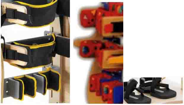
I had the idea from Standers structure. Standers are used by people with mild to severe disabilities such as spinal cord injury, traumatic brain injury, cerebral paisy, spina bifida, muscular dystrophy, and post polio syndrome.
Standing devices are used in a variety of settings including:
In the home and workplace activities,
• Classroom activities,
• Children's hospitals and therapy centers,
• Rehabilitation.
This picture below shows the initial design.


For this assignment I’ll use the router cnc milling machine.
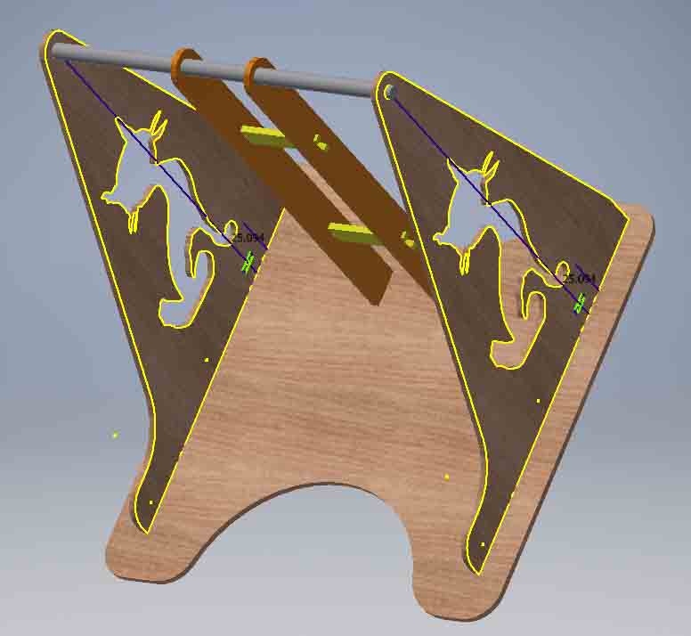
Fig 1. 3D model of the assembled standing frame on Inventor software.

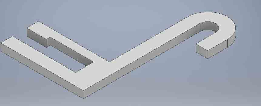
The first is too heavy and not flexible, it’s no good when working with MDF.
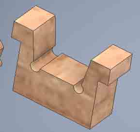
Fig 6. This is a better design for this application, it’s more flexible and the hook is more stable when working with MDF.
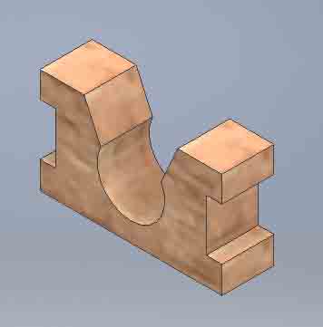
Fig 7. Design of the hook of the table on Inventor.
The next show
the part list and simulation.
Bipedestador part list
Part list, File on PDF
Simulation Bipedestador
Showing the Bipedestador simulation.
The work flow on
Multicam 3000 Series.

BIPEDESTADOR
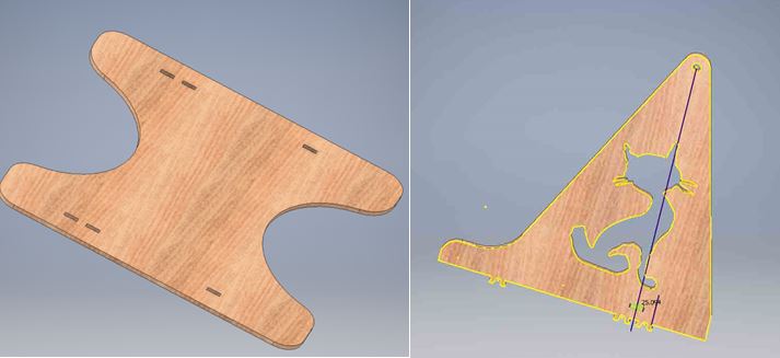
base
Frame
Click
Hook
Side
parante