Wheek 5: Electronics Production.
Made ISP board.
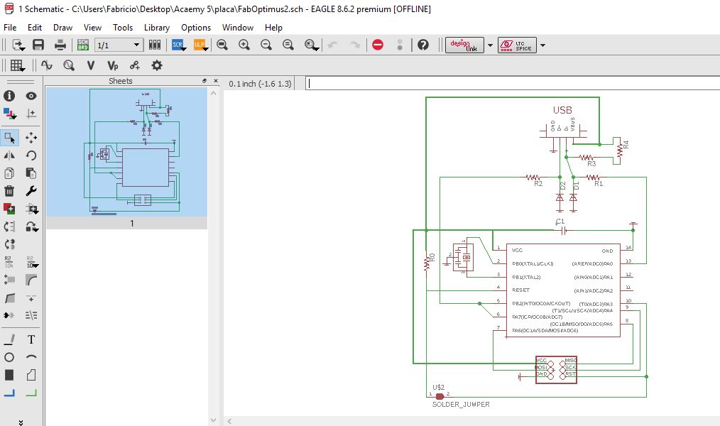
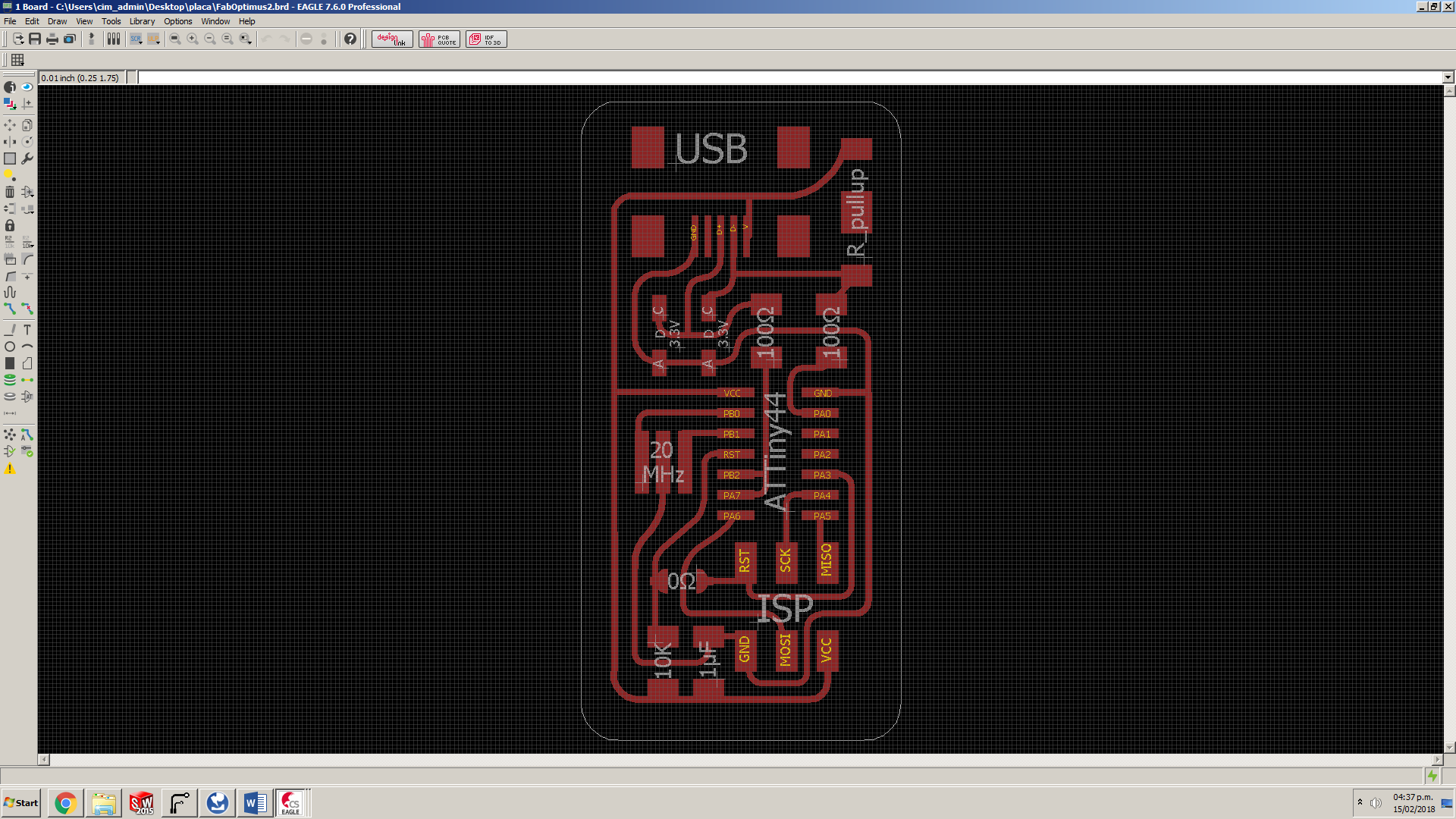
This week assignment was to make a Fab ISp board and system programmer for AVR microcontrollers. I decided to make the Ali version of the Fab ISP. To have a better overview of the board I downloaded the eagle files in order to see better its components, the schematic and board. The files were FabOptimus2.sch and FabOptimus2.brd use them. the pictures below show both the schematic and board of the ISP.
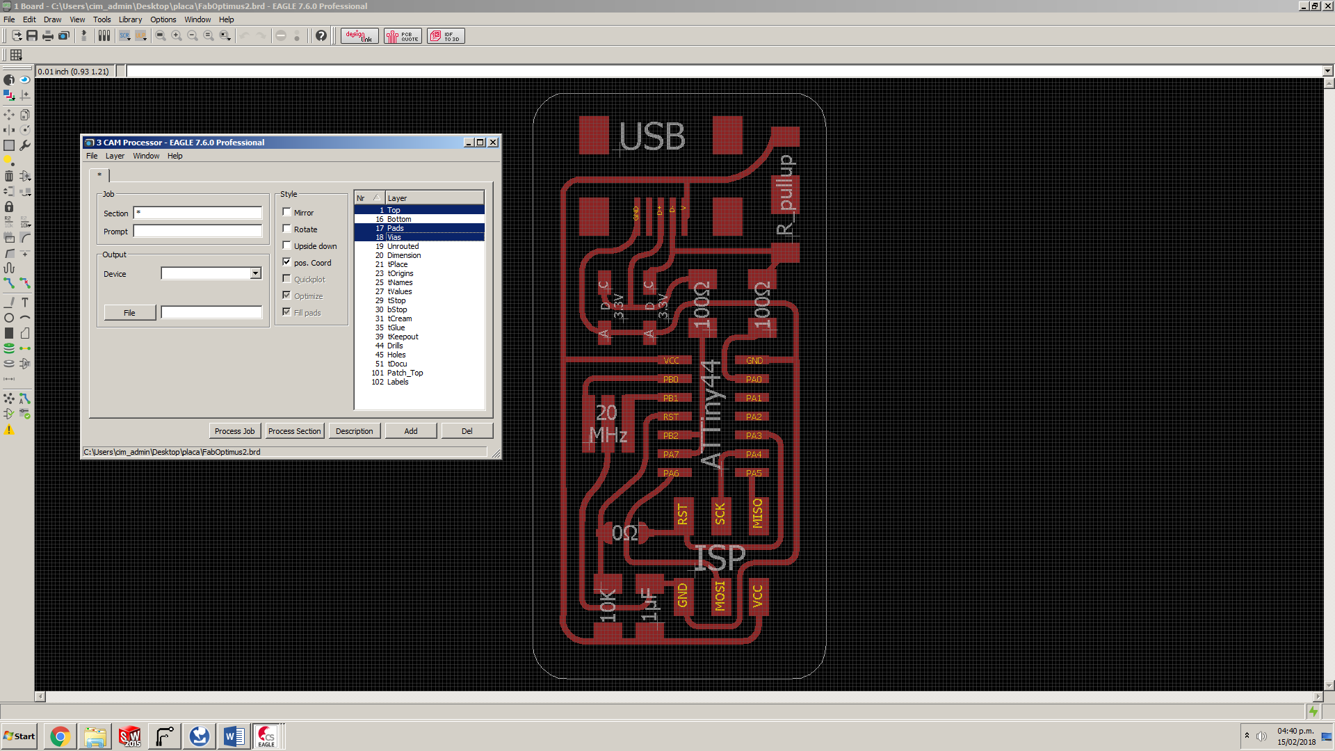
For the machining of the PCB we use Roland Modella MDX - 540 CNC router, and Flat CAM processor as the CAM software, It’s a free and open source CAM processor which is highly compatible with EAGLE and excellent for PCB manufacture. In order to have a proper flow of information between the files, EAGLE has a CAM processor incorporated in its board environment. It generates a file which can be later post processed with a cam software to generate the g-code. In this case, we work with smd components, so all of them will be on top of the board. We selected the layers we will machine.
Cam Processing.
Cam stands for computer aided manufacture. The software allows the communication between the Cad desing and Machine. I used flatcam for this purpose, I imported the file generated on the cam processor on eagle
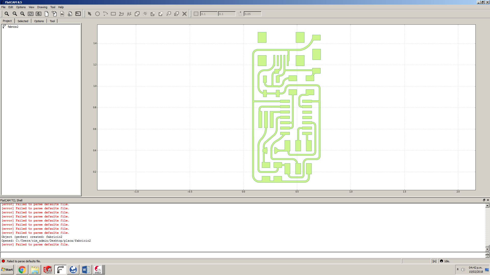
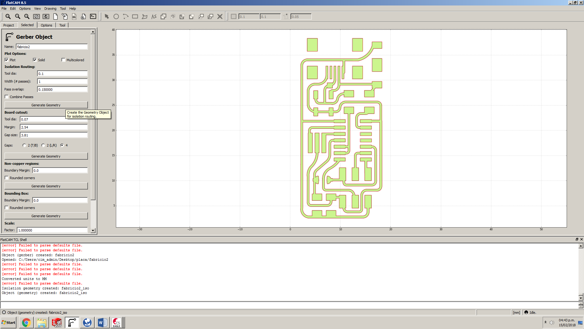
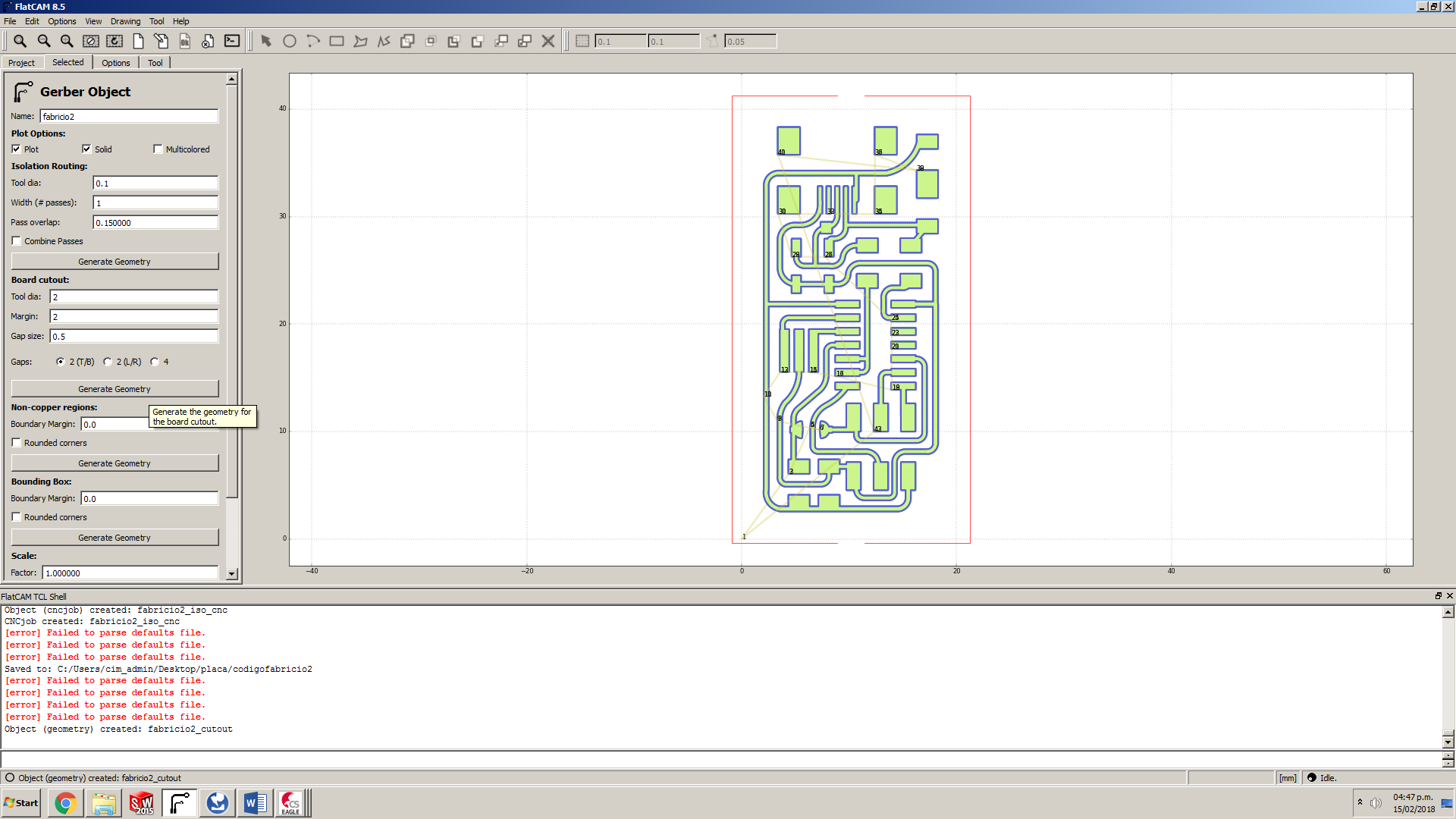
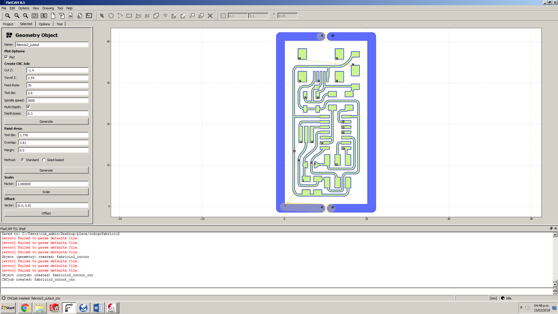
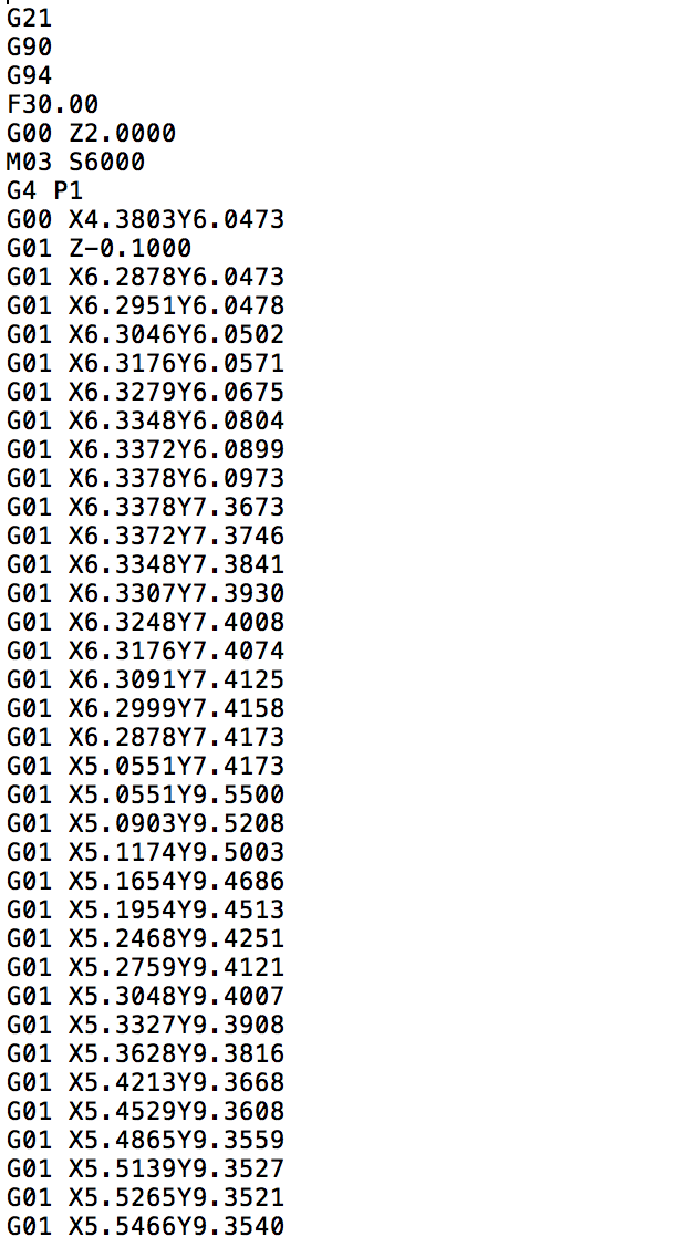
Finally, the Flatcam outputs the G-code of the PCB. The G code is the universal machine code for CNC machines.
Machining.
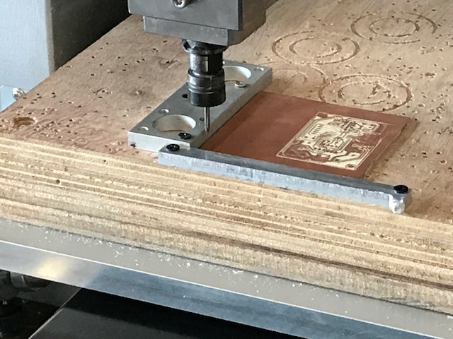
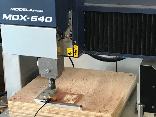
Now it’s time for the machining of the board. The first thing to do is select the proper mill for PCB making. We used, as mentioned, the Modela MDX – 540 milling machine. It is known for its excellent performance in PCB making and high quality mills.
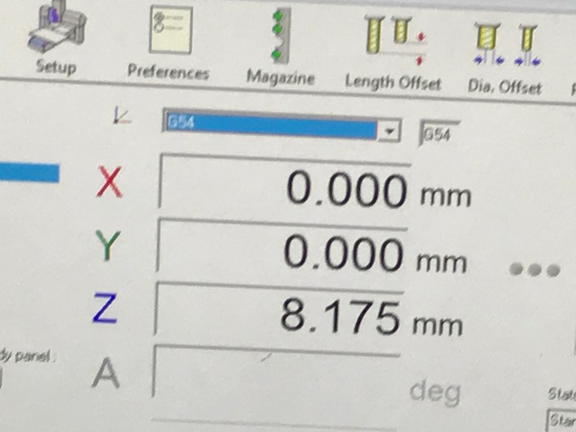
Then I proceeded with the setting up of the workspace. First thing to do was to set the zero for all axis (x, y and z)
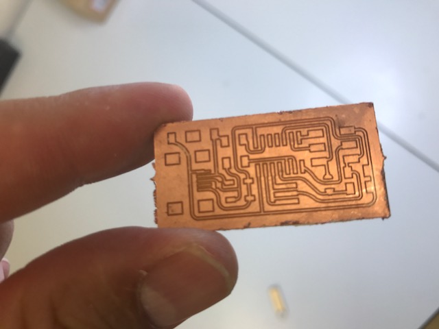
And this was the final result:
Soldering.
When the boards were done, I proceeded to the soldering. For this I used two methods. First one was soldering iron and lead soldering and the second one was heath gun soldering with flux paste.
First I tried the classic method. For this I needed a proper set up: the tools needed were: Soldering iron, lead, two side tape, soldering station, tweezers and a magnifying glass.
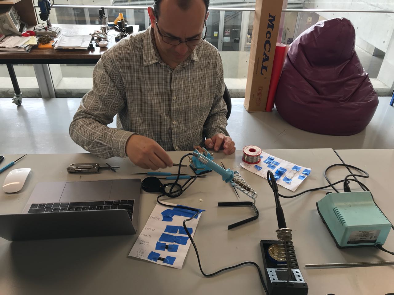
Fig 12. This was my set up with the tools I used for the soldering .
The workflow I used was first solder one pin on the board and fill it with lead, then grab the components with the tweezers and place them on the respective trace on the board and with the soldering iron keep the component on place. One pin at a time.
This method was hard, the components were small and it was required a minimum skill level and experience soldering. I used some tools as support for the soldering such as GOOT solder assistant kit and a knife.
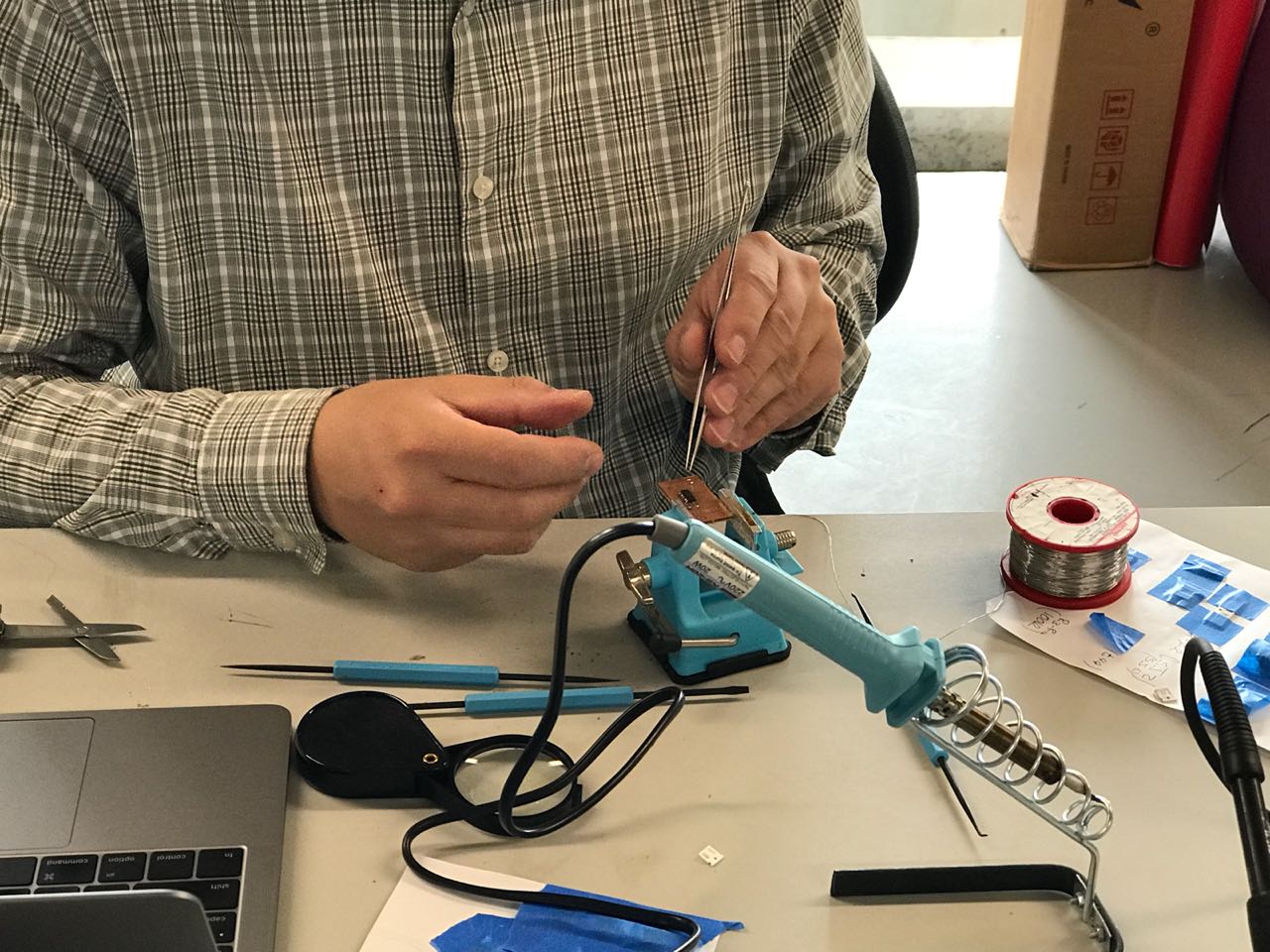
Fig 13. Components were tiny and hard to keep them still.
Finally the board was solder properly with no shorts visible.
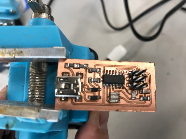
Fig 14. Board successfully soldered .
Now I tried to solder the same board but with the heath gun method. For this method I only needed a heath gun and some flux solder paste.
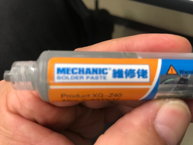
Fig 15.Solder Flux .
The workflow was to fill all traces with solder flux, then set the heath gun at 400 degrees celcius and wait until all components rest in place. They align automatically and no need to relocare them with the tweezers.
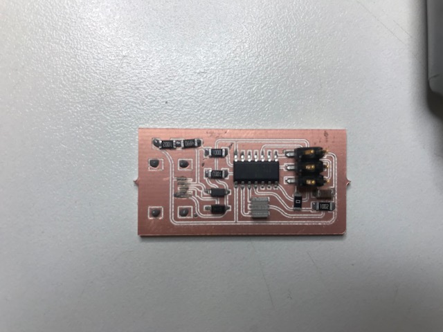
Fig 16. All components in place on the board before heating with the heat gun
Now use the heat gun about 10 minutes to 400C.
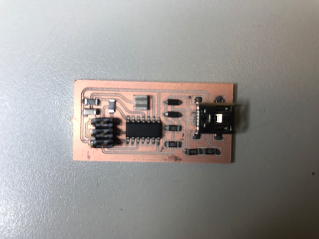
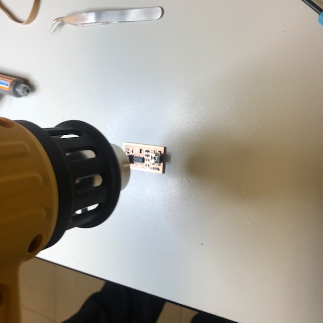
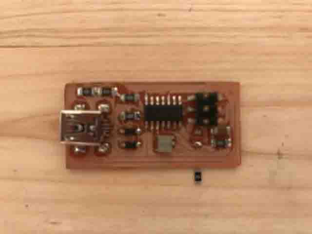
Fig 18. Final board, soldered properly. In order for the ISP to be a programmer and work we have to remoce the 0 Ohm resistor and then It's ready.
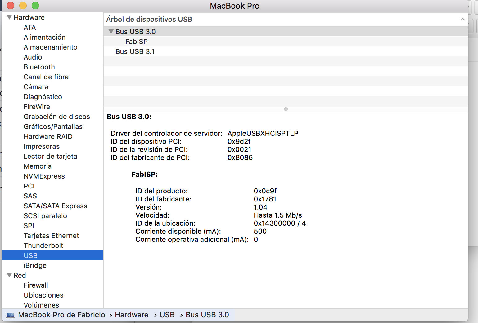
Programming.
Go to Programing ISP on Ubuntu
Board (Eagle)
Schematic (Eagle).
Board CAM