
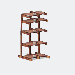
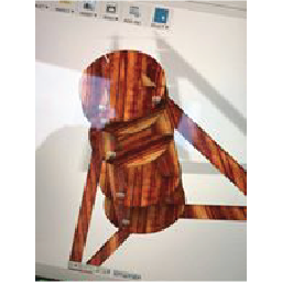
This week's assignment was to MAKE SOMETHING BIG! I wanted to move forward with my final project, so I decided to fabricate the cold brew tower, for the Fab-Brewer. I used the design I had previously used for Computer Controlled Cutting, so I re-parametrized the design and adjusted it to the dimensions of the real tower, and the characteristics of the materials I had available. I did not have time to go to UTEC this week, so I used the materials available at work. I used 9 mm thick MDF. These are pictures of the design and a rendered version.
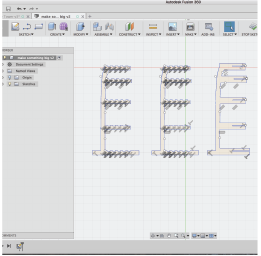
I saved the sketches as a .DXF file, and sent them to illustrator to generate an idea of how the pieces should be positioned while cutting.
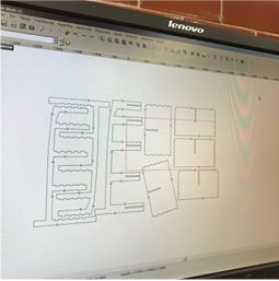
Like i mentioned earlier, I did not have time to go to UTEC and cut, so I had to use the machines and the softwares available at work. We use "Enrouter 6" as a CAM software. When I imported ther DXF files, i had some issues. Apparently, whenever files are exported as .DXF from 3D design softwares (such as fusion, solidworks or inventor), new lines are generated on top of some of the polylines of the skecthes. This generates problems when generating toolpaths, since the lines are not part of any closed sketch. Also, when importing to Enrouter, the sketches seem to be arbitrarily enlarged.
The first problem can be solved by fusing all of the lines and checking to see which segments of the sketches have arrowheads within them. Once located, expload the sketch and ungroup it. Then procceed to delete all of the lines which had arrowheads on top of them. Delete a "single" line as many times as necessary, until there is no line, and you have to redraw a new one (or just click Ctrl+Z). Refuse the sketch and, if every repeated line was deleted, voilà!, the sketch will turn blue and it will be able to be processed.
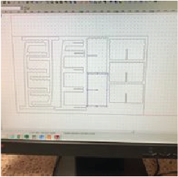
The second problen can be solved by resizing the sketches. When selecting the scaling option, Enrouter will ask for a factor. Because ot had scaled it arbitrarily, I had no idea how much I had to rescale it. Luckily, Enrouter provided me with the maximum width of the design and since I knew the specified width, I managed to find the factor and obtain the real value. Once the designs were rescaled to the original size, i re-positioned them to fit the bed.
At work, we have a MultiCam milling machine. It works just like any other milling machine, so the steps I followed pretty much cover most of the milling machines out there.
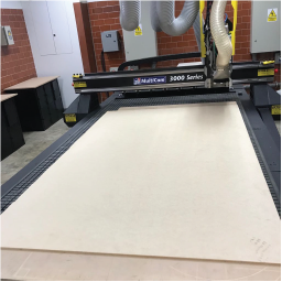
First. After laying out how the pieces will be set within the MDF board, start generating toolpaths for every piece. The toolpath will depend on settings such as "Tool Diameter", "Cut Depth", "Total Depth", and so on, and so forth and what have you. In this case, I used a 6 mm wide tool, and eventhough the MDF was only 9 mm thick, I calculated for a total depth of 10 mm, since sometimes the board is uneven.
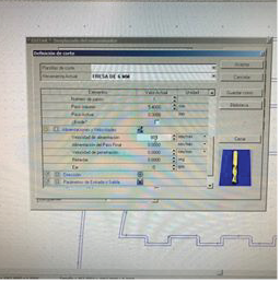
These are some of the settings I used:
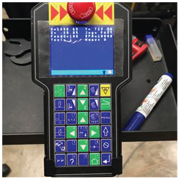
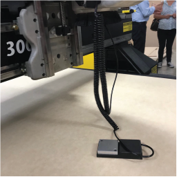
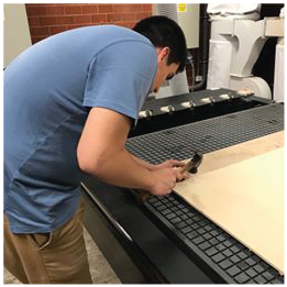
I then proceeded to set the origin point (or zero-point) for the machine. I used the Control-Panel to manually move the tool to the position where I wanted to, well, position the tool. I also used a special tool to specify the 0 on the z-axis. Most milling machines work with tools like these one.
Next I had to secure the MDF board to the bed using nails. I could have used screws, but because I was taking up a lot space with the pieces, I feared there would be no space for screws. The nails also helped me secure the pieces. Enrouter does not allow for tabs to be used, so nails are the least-damaging way of firmly securing the pieces.
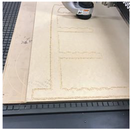
So, next, I sent the g-code over the internet and started machinig.
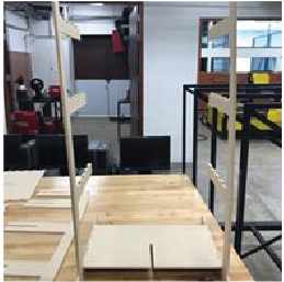
I was afraid the design would not work, so I started working on a second idea, just in case. It wasn't, however, a very good idea, so I decided to stick to my guts. I still think that with some extra work, this second idea could be suitable for my project, but right now, it's not something I quite like.
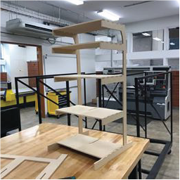
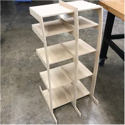
In the end, the pieces came out quite well. I used 8 pieces in total.
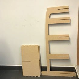
Thanks to the precision of the MultiCam, assembling was super easy. I did not need to modify the dimensions of the pieces manually, nor did I need to exert a ridiculous amount of strength in order to press-fit the pieces.
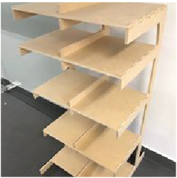
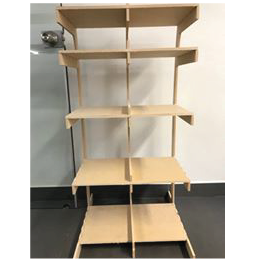
Finally, I obtained my Cold-Brew tower, for the FAB-Brewer. Unfortunately it is quite infirm, so I'll need to modify the design if i want it to be able to bear some weight.
You can find both the .f3d design and .dxf files within the following links: