

For this week's assignment, I decided to start working towards my final project. Like I mentioned in previous assignments, the idea is that the user can decide the rate at which the cold water should drip when brewing the coffee. The dripping rate will be controlled with a peristaltic pump - and a stepper motot - but the user will need to set the speed using a selector. Thus, the only input device will be this selector. I;ve decided to manufacture it using a potentiometer. With this in mind, I set out to design my board using Eagle, like I learned during Electronics Design. Here's my schematic.
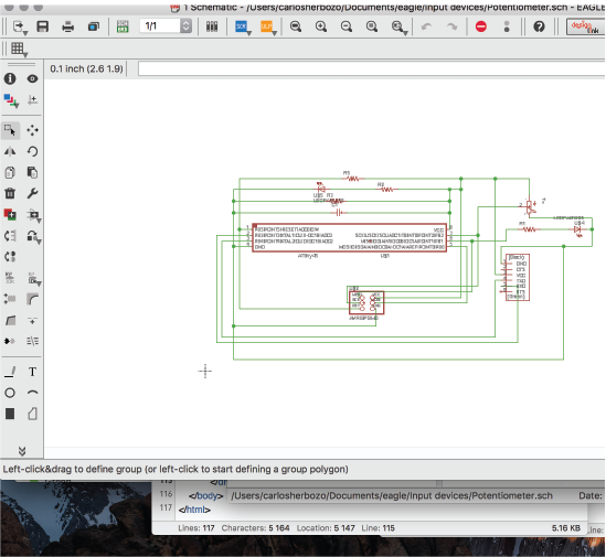
The first things I had to figure out were how a potentiometer works, which microcontroller to use and how it was wired inside. So first thing's first. Which microcontroller to use? I used the ATtiny 45, because of the following reasons:
And how does a potentiometer work? Well, it's basically a variable resistor. Its value in Ohms can change, unlike a common resistor. It has 3 pins, one of wich connects to VCC, one to the microcontroler and one to ground. When the resistance is changed, the voltage delivered to the microcontroller changes as weel. In this case, the board is supplied with 5 volts, so the microcontroller will recieve data from the potentiometer as numbers within a from 0 to 1023 - a range which represents 0 to 5 volts respectively. The potentiometer is thus an analog Input device, unlike a button which gives data as 0 or 1, 0 or 5 volts. Now, because I need the user to be able to turn the potentiometer easily, I'll be using a true-hole component, rather than just an SMD one, eventhough they're available at the lab.This is purely a UX decision, and it shall not change the overall behaviour of the board.
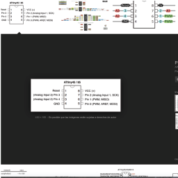
Figuring the microcontroller was another story entirely. While reading the Datasheet, I discovered that the ATtiny 45 has now serial ports, so in order to read the data either I had to use the software serial library, or figure out a new way. My instructors told me that they hadn't been able to use the software serial library with ATtiny 45 before, so I deciced to try a different way. I noticed that the chip has some PWM pins, so I decided to connect a LED and control its intensity according to the values of the potentiometer. More on this during OUTPUT DEVICES. In the end, this is what my board looked like.
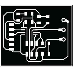
I used what I had learned during electronics production to mill and solder my board, and in the end, this is what it looked like:
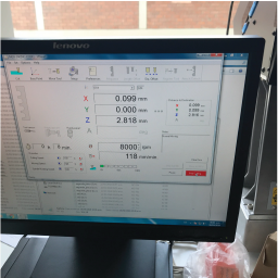
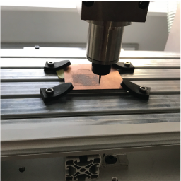
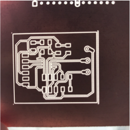
After soldering the board, I programmed it. The first thing i had to do was burn the bottloader from the Arduino Environment. The configuration is different to the one used when programming the Hello-world board. These are the parameters I needed to select:
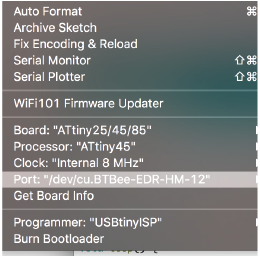
At first, I used the AVR ISP mkII, but it didn't work, then I changed to my FAB-ISP and it burnt alright.
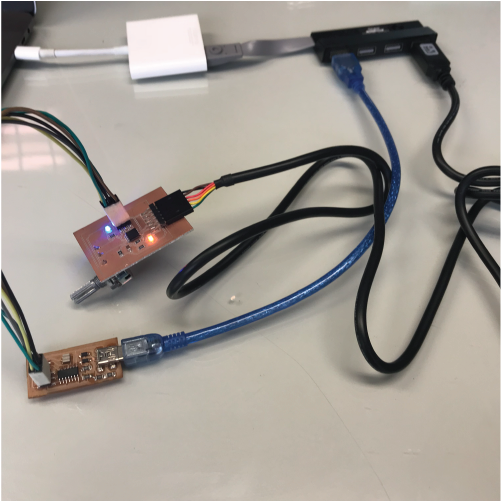
The code I used is quite simple. First, I read the potentiometer as an analog input. Then, I map its values (originally 0 - 1023) to 0 - 255. Then i use PWM to control the intensity of the LED. Here's my sample code.
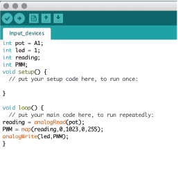
After compiling and uploading it.... IT WORKS!
Here's a video:
You can find my files in the following links: