applications & implications
MAY 23 - may 30
● The goal for this week was to propose a final project that integrates the range of units covered, answering: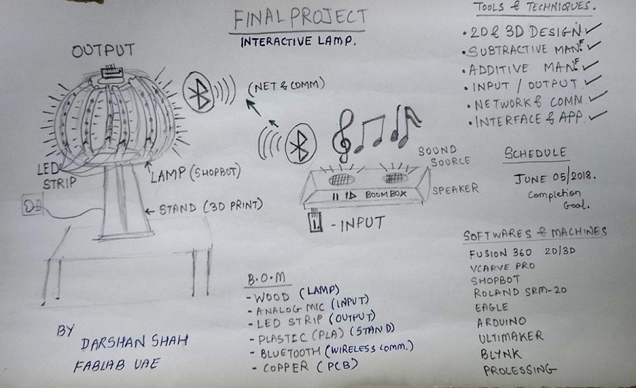
● What will it do?
It's an interactive lamp of material 12mm Plywood with the help of computer controlled machining on Shopbot and the Trotec Laser Cutter using the 12mm transparent Acrylic, both the spine, top and bottom base will be joined using slot design based on the lamp I made in Week 08.
The lamp lights itself up by the use of a LED strip which will be placed inside. As mentioned the LED strip shall be working through a PCB and the LED acts as an output device.
The output device will be connected to the input device, which will be an analog microphone on a PCB. So as per changes in the pitch or tone of the sound recorded by the microphone input accordingly the LED output will react to the same.
In order to achieve the above explained event, I shall program the boards, the input microphone to record the sound levels and communicate the same with the LED output which also will be programmed to express itself in a particular pattern of colors.
Both input and output shall be programmed and communicate with each other on the same board or two different boards if needed with a wired connection.
Also, I shall plan for future development, to create an application of some sort on a smartphone device which will communicate with the output device and accordingly a user can control the lights.
This is the overall explanation of what my proposed project will do.
● Who's done what beforehand?
- I found one of the previous year projects which were some what on the similar grounds where they used neopxils in relation with sound and their documentation helped me a bit to understand the working of the same.
Donato Polignone who made a luminous smart gadget, a beautiful project overall.
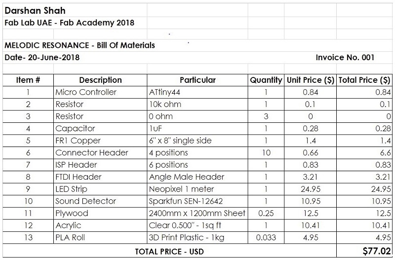
● What materials and components will be required?
The following list of materials and components shall be required:
12 mm Plywood & 12 mm Transparent Acrylic for Lamp Body.
3D Printed componentPLA / ABS.
Analog microphone / Sparkfun Sound detector- input device
Neopixel LED strip- output device
ATTINY44- Micro Controller
FR1 COPPER material to create the PCB for Input and Output Device.
● Where will they come from?
All of the above mentioned material and parts are either available in the lab or I have/will make design, assemble and integrate in the lab.
● How much will it cost?
● What parts and systems will be made?
The following parts and systems will be made.
The main body of the Lamp.
3D Printed component to place the PCB in the Lamp.
PCB input and output device boards with:
Analog Microphone & LED Strip
Programming the above devices for a specific requirement.
Wired communication between the boards.
Future Dev - Interface or Application to communicate with output device through a smartphone.
● What processes will be used?
2D Parametric Modeling.
3D Modeling.
Subtractive manufacturing: Laser Cutting/ Vinyl Cutting
Additive manufacturing: 3D Printing
Computer-Controlled Machining.
Electronics Designing.
Electronics Production.
Input & Output Device.
Networking and Communications.
Interface and Applications.
● What tasks need to be completed?
The following tasks are either are completed or are in progress for testing purpose:
testing
2D Parametric ModelingComputer-Controlled Machining
Input Device: Analog Microphone
Wired Networking and Communications
Output Device: LED Strip
Wireless Networking and Communications
Interface and Applications
● What questions need to be answered?
The placement of the LED strip, I need to work and answere the question that where I shall place the LED strip to make it attractive and also a neat product.
Also the placement of the Input and Output device boards, Input shall be placed on a musical instrument with the help of a 3d Printed component.
Where as, the output device has to be placed inside the lamp in such a way that the wires and connections are not visible and does not affect the working operation of the LED strip.
Also the power source for both the boards is the important aspect I need to work on.
● What is the schedule?
tentative dates
Electronics Design & Production (Input/Output): 12th June 2018.3D Modeling & Additive Manufacturing: 17th June 2018.
2D Parametric Design & Computer Controlled Machining: 12th June 2018.
Programming and Testing 14th June 2018.
Assembly & Integration: 15th June2018.
Video, Slide and Final Product: 19th June 2018.
The estimated date of project completion from my end is 19th June, 2018.
● How will it be evaluated?
The project shall be evaluated mainly on the following aspects:
The Lamp design as a well made, good looking product, also safe and made with use of non toxic materials.
The working application of the lamp for a user preference in regards to the display of LED light strip reacting to the sound of the environment.
Accurate communication between the boards/ input and output devices.
User application to operate the project on smartphone.
No wirings shall be visible, neat and tidy overall product.
Testing all the connections, networking and communication.
User friendly operation, anyone can use it.
● Projects can be separate or joint, but need to show individual mastery of the range of skills covered
It is an individual project and expresses the range of skills mastered by me during these multiple weekly assignments.
● Where possible, you should make rather than buy the parts of your project
As explained above, all of the parts of my project are available or will be made and created by me.
● My responsibility was to answer all of the above questions and in a way that my final project answers those questions.
I hope I have answered all the questions in regards with my project.