This weeks assignment is to do with Input devices.We have to work with a sensor and have to read data from them.A sensor is something
that can converts a real world property like temperature,pressure,distance into data that a computer can process.
From this weeks lecture,I came across lot of sensors like temperature,proximity,ultrasonic sensor,pressure,sound etc.So to start with I am using ultrasonic sensor
to measure the distance using ultrasonic sound waves which is transmitted and received back.I am using HC-SR04 sensor for this weeks assignment.
HC-SR04 SENSOR
The HC-SR04 ultrasonic ranging sensor provides 2cm to 400cm of distance measurement functionality with an accuracy up to 3mm.
Each HC-SR04 module includes an ultrasonic transmitter, a receiver and a control circuit.It works on the principle of sonar to transmit a sound wave and
measuring the time taken to receive its echo back.
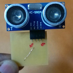
There are only four pins on the HC-SR04: VCC (Power), Trig (Triggering the waves), Echo (Receiving the waves), and GND (Ground).
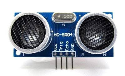
HC-SR04 sensor
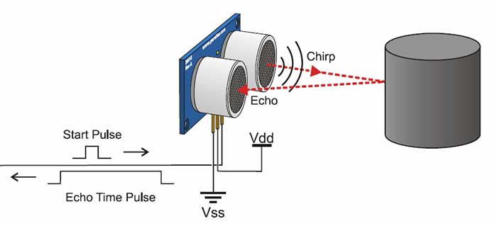
working of the sensor
you can read more about HC-SR04 SENSOR
DESIGNING THE PCB
I am using Autodesk Eagle to design my Board.Following Neils Boards I choose ATtiny 45 as the IC.The pin configuration of ATtiny 45 is shown below:
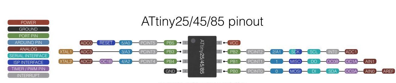
ATtiny 45 pin configuration
Apart from Neils board I am adding 2 Leds for displaying wheather the
Leds are in range or not.One led is on when the object is in range and the other is on when the object moves
beyond the sensors range.
Components Required
ATtiny45
HC-SR04 sensor and its pin header
AVR ISP SMD header for programming the board
FTDI SMD header powers the board and allows it to speak to the computer
10 kilo-ohm resistor
499 ohm resistor x 2 for leds
10 microfarad capacitor
smd led-2 Nos
Schematic sketch
The schematic sketch and the board design are as follows:
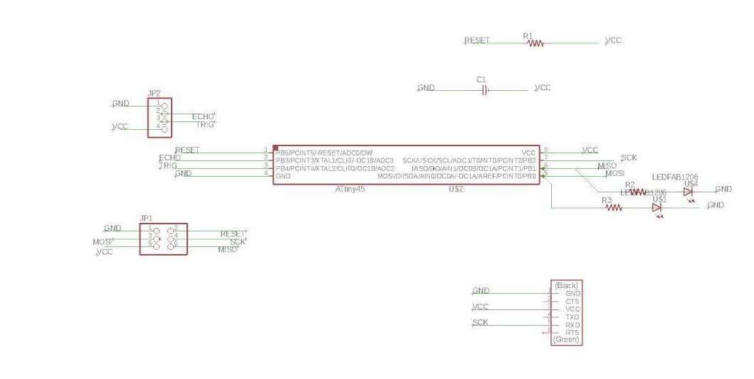
Schemaic sketch of the board
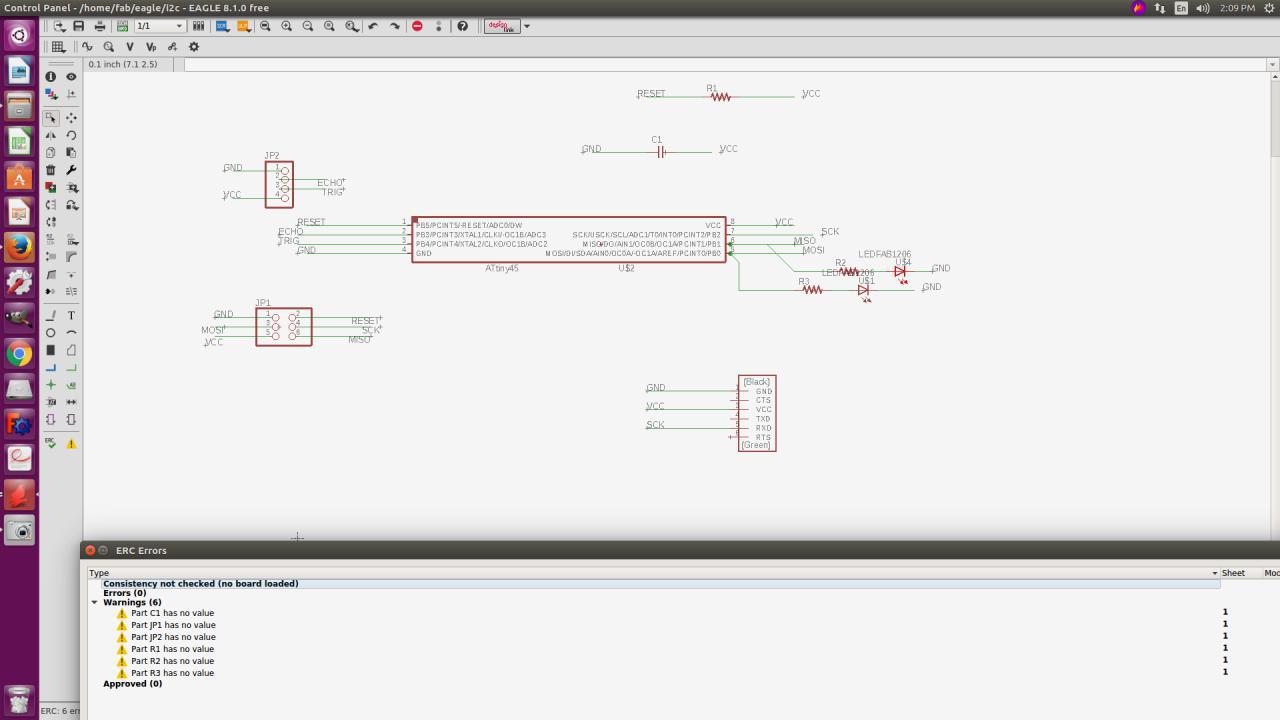
Schemaic sketch after ERC checked
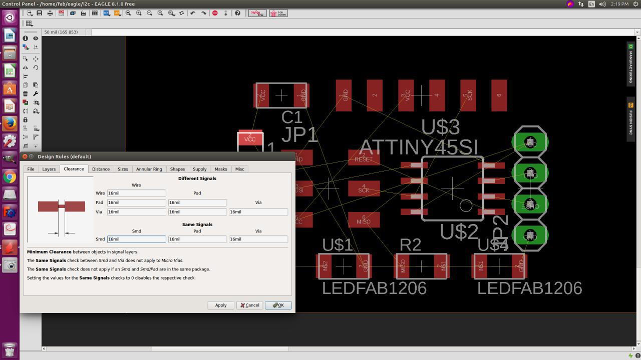
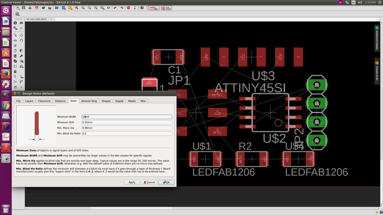
After completing the schematic sketch i switched to board for arranging the components.In Switching to board we firstly have to set the design rules of size
of the traces to 18 mil and the clearance to 16 mil
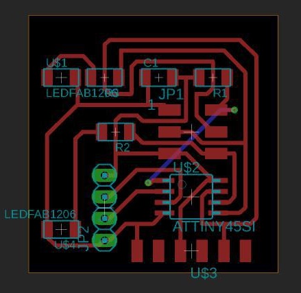
After arranging the components I have to drill hole for connecting the Reset of the microprocessor to the ISP pin header using Jumper wires.
The final board design after performing the DRC checks is:
MILLING THE BOARD
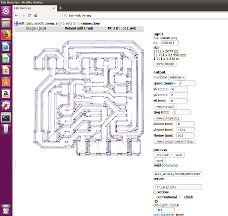
For milling the board I am using Roland Modella MDX-20.
1/64th mill is used for milling the traces
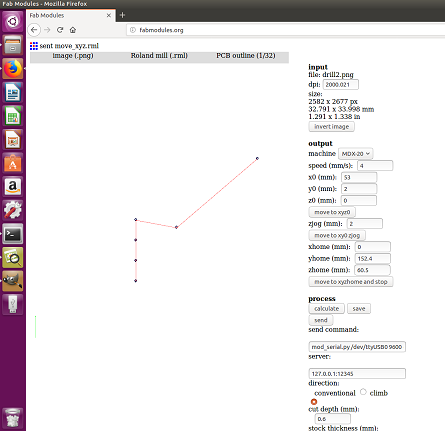
For cutting 1/32 nd inch bit is used
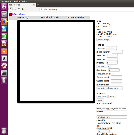
Fabmodules is used as the print manager
The setting up of modella MDX20 and using is explained in my Electronics production week
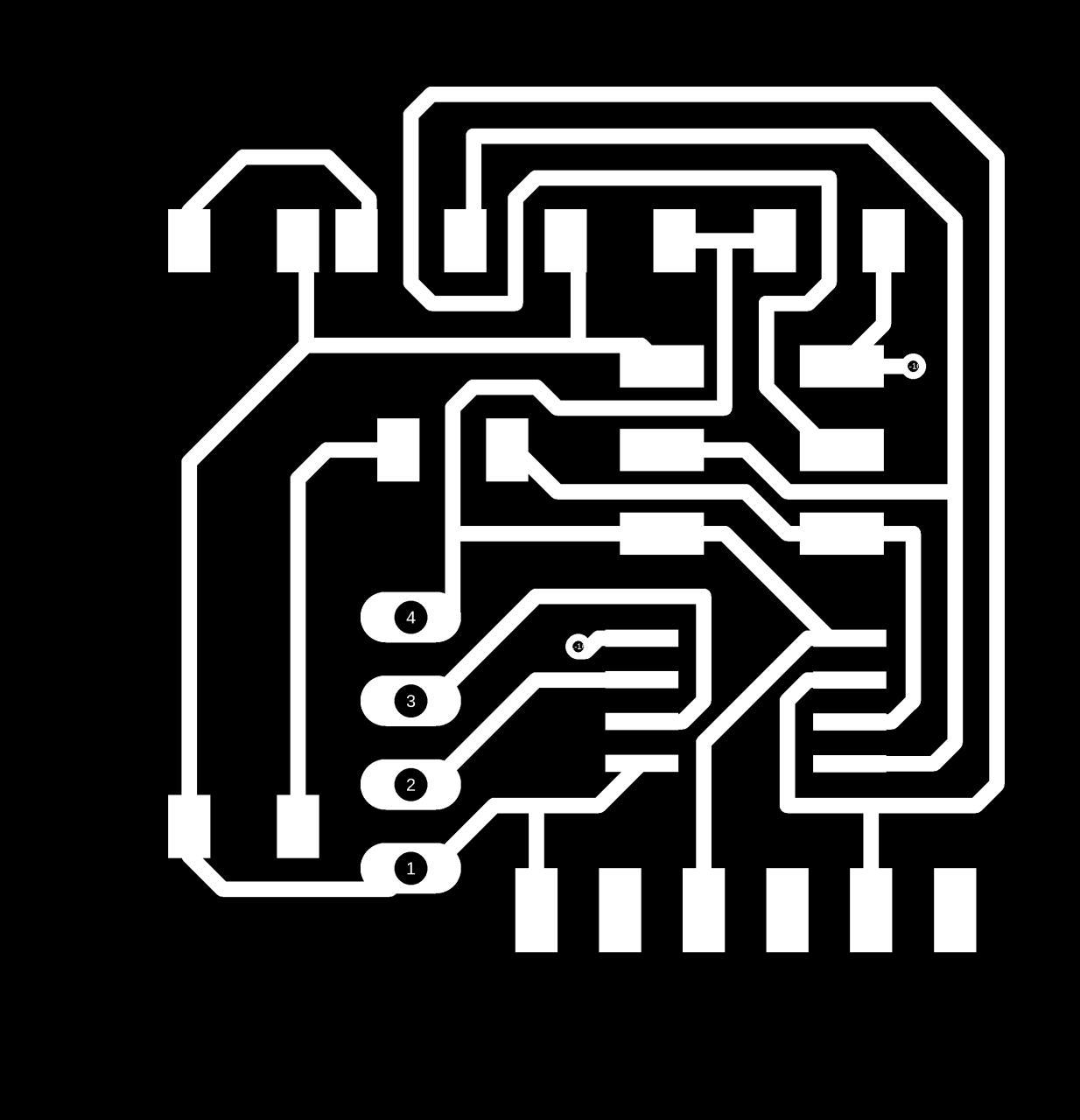
Traces for milling
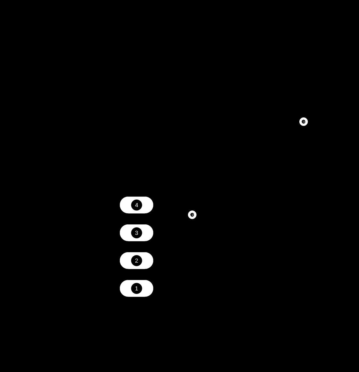
outline for drilling

outline for cutting
Now I went on to mill my board and the board after milling the traces are as follows:
 <
<
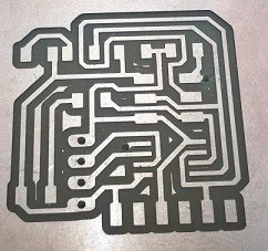
PCB after milling traces
After soldering the components
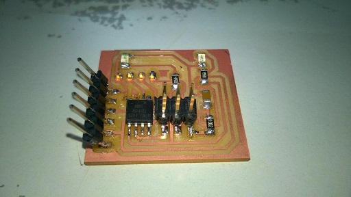
Connected with the sensor
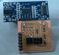
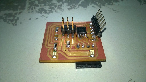
sensor connected to the board
back side of the board showing the jumper wire
PROGRAMMING THE BOARD
For programming my board for the sensor,I used arduino IDE.In Aurdino first
we have to select the programmer,board,processor and the clock before writing the program.For my board the details are as follows:
programmer- USBtiny
Board-ATtiny 25/45/85
Proces MHz internal
I reffered many programs using Arduino and HC-SR04 sensor in the internet.I came across a program in for measuring the distance
using HC-SR04 sensor.Firstly,I did a program which can make use of my leds
which I designed in my board.The program is written is such a way that the red led will light upto 10 cm and from 10 to 100 cm orange
led will lit up.After that again the red led lights up.The code is as follows:
                   #define trigPin A2//defining trigpin to A2/PB4
                   #define echoPin A3//defining echopin to A3/PB3
                   #define led PB1//defining led to PB1
                   #define led2 PB0//defining led2 to PB0

                   void setup() {
                   pinMode(trigPin, OUTPUT);
                   pinMode(echoPin, INPUT);
                   pinMode(led, OUTPUT);
                   pinMode(led2, OUTPUT);
                    }

                   void loop() {
                   long duration, distance;
                   digitalWrite(trigPin, LOW);//setting trigpin to low
                   delayMicroseconds(2);
                   digitalWrite(trigPin, HIGH);//setting trigpin to low
                   delayMicroseconds(10);
                   digitalWrite(trigPin, LOW);
                   duration = pulseIn(echoPin, HIGH);
                   distance = (duration/2) / 29.1;//soundwave speed-distance conversion
                   if (distance < 10) //less than 10cm
                   {
                        digitalWrite(led2,HIGH); // Red led goes on
                        digitalWrite(led,LOW);  // orange led goes off
                   }
                   else if (distance >= 100 || distance <= 0)
                   {
                       digitalWrite(led2,HIGH); // Red led goes on
                       digitalWrite(led,LOW);  // orange led goes off
                   }
                  else //between 10cm to 100cm
                   {
                       digitalWrite(led2,LOW);// Red led goes off
                       digitalWrite(led,HIGH);// orange led goes on
                   }

                   delay(500);
                    }

               }
After programing I have read my sensor with the help of a measurement tape and it was close enough.The video is
shown below:
After this program I have modified the program to read the output of the sensor from arduino serial monitor.The program is as
follows:
                   #include
                   SoftwareSerial serial(A1, 1);//rx pin of ftdi header as receiver and mosi as tx
                   const int trigPin = A2;  // defines pins numbers
                   const int echoPin = A3;  // defines pins numbers
                   long duration;  // defines variables
                   int distance;   // defines variables
                   void setup()
                   {
                    pinMode(trigPin, OUTPUT); // Sets the trigPin as an Output
                    pinMode(echoPin, INPUT); // Sets the echoPin as an Input
                    serial.begin(9600); // Starts the serial communication
                   }
                  void loop()
                  {

                   digitalWrite(trigPin, 0);// Clears the trigPin
                   delayMicroseconds(2000);
                   digitalWrite(trigPin, 1);
                   delayMicroseconds(5); // Sets the trigPin on HIGH state for 5 micro seconds
                   digitalWrite(trigPin, 0);
                   duration = pulseIn(echoPin, 1); // Reads the echoPin, returns the sound wave travel time in microseconds
                   distance = duration * 0.034 / 2; // Calculating the distance
                   if
                   (distance > 100)
                    {
                     serial.println("out of range");
                    }
                  else
                   {
                    serial.print("Distance: "); // Prints the distance on the Serial Monitor
                    serial.print(distance);// Prints the distance on the Serial Monitor
                    serial.println(" Cm");// Prints the distance on the Serial Monitor
                   }
                  delay(2000);
                  }
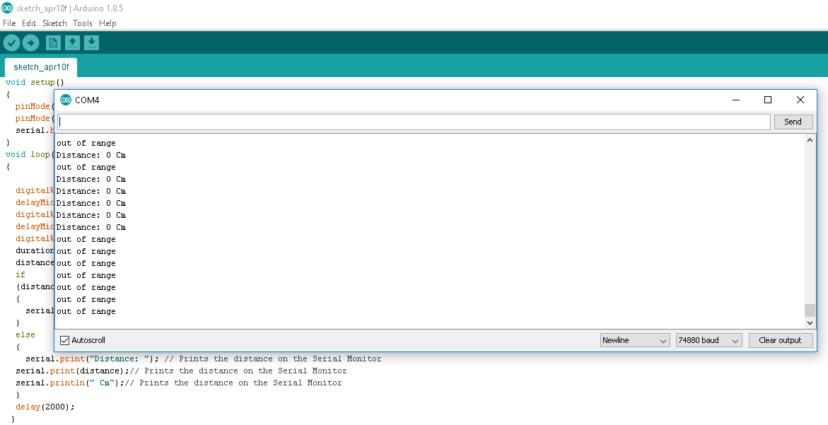
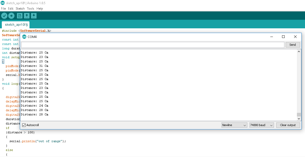
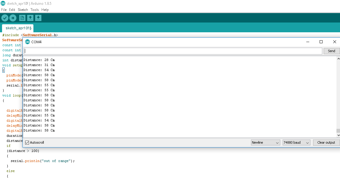
SERIAL MONITOR OUTPUTS
Group Assignment
In group assignment we have to measure the analog and digital signals in an input device (we are using sensor).
Usually a microcontroller takes two types of input analog and digital and so we are asked to measure these.Sensors can be of digital and
analog type.
For analog level measurement we used a LDR sensor
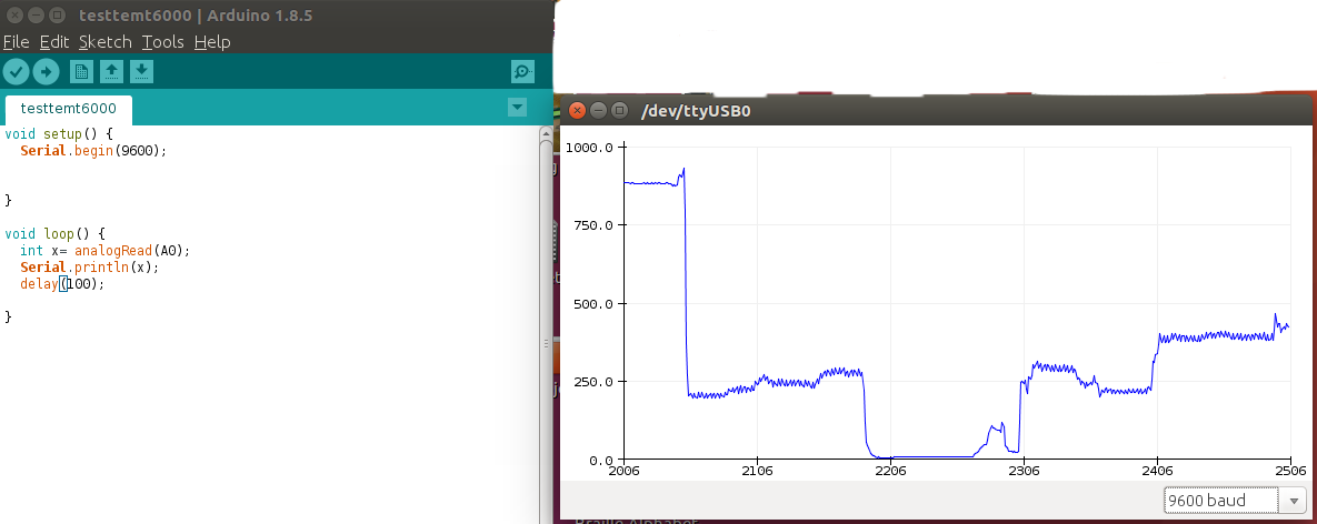
sensor connected to the board
Digital Sensor produce discrete values of 0 and 1. Discrete values often called digital (binary) signals in digital communication. For digital signal measurement we are using Arduino connected with PIR sensor.
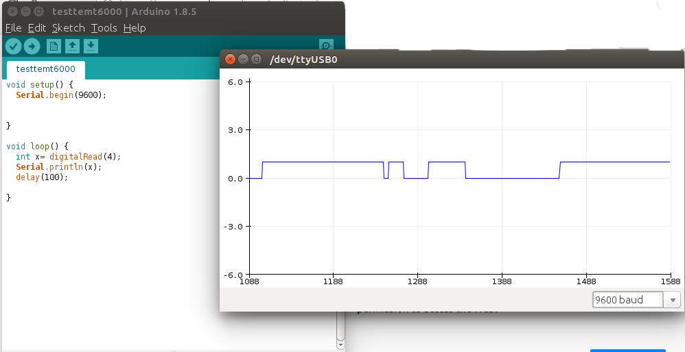
sensor connected to the board