My task for this week is to programme my echo board that I have done previously. Particularly, what we are assigned to do is that to control the LED light using switch. For doing this project, we have to go through the datasheet of Attiny44 in detail.
ATtiny44 Datasheet Review
8-Bit Microcontroller with RISC Architecture with Most Single Clock Cycle Execution
– 32 x 8 General Purpose Working Registers
– 4K Bytes of In-System Programmable Program Memory Flash
–56 Bytes of In-System Programmable EEPROM
–256 Bytes of Internal SRAM
Peripheral Features
– One 8-Bit and One 16-Bit Timer/Counter with Two PWM Channels, Each
– 10-bit ADC
– Programmable Watchdog Timer with Separate On-chip Oscillator
– On-chip Analog Comparator
– Universal Serial Interface
Special Microcontroller Features
– debugWIRE On-chip Debug System
– In-System Programmable via SPI Port
– Internal and External Interrupt Sources
– Enhanced Power-on Reset Circuit
– Programmable Brown-out Detection Circuit
– Internal Calibrated Oscillator
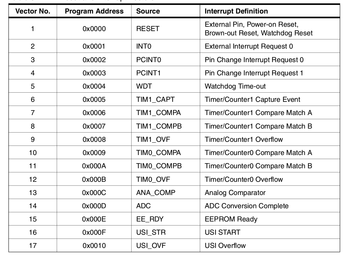
Interrupts
Interrupt mechanism is an important concept while working with microcontroller,so lets have a breif introduction.Figure given below shows the pin diagram of ATtiny44.
The External Interrupts are triggered by the INT0 pin or any of the PCINT11:0 pins even if the INT0 or PCINT11:0 pins are configured as outputs,thus provides a way for generating software Interrupts. Pin change 0 interrupts PCI0 will trigger if any enabled PCINT7:0 pin toggles. Pin change 1 interrupts PCI1 will trigger if any enabled PCINT11:8 pin toggles.
So in short, I have got the pin out configuration, different registers and timers available in the chip from the data sheet. Its also shown that how to access the chip. The detailed description really made me enthusiastic to do this week assignment.
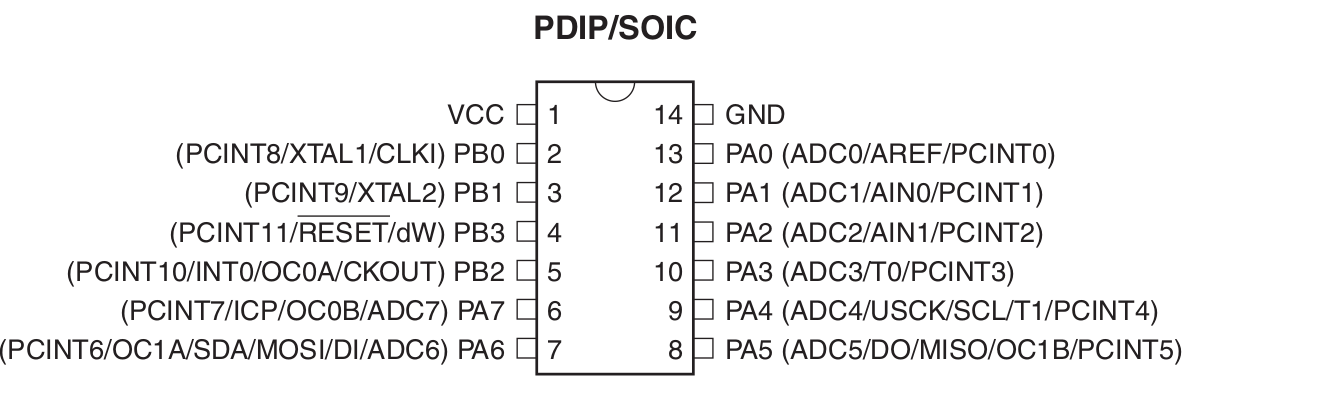
From the pin out diagram we should be able to understand that there are two ports in the chip viz PORT A and PORT B where PORT A has 8 pins and PORT B has 4 pins. These are the input and output pins where external components are connected.
Programming with my Echo Hello World Board
Before moving to programming I refferd my schematic with datasheet.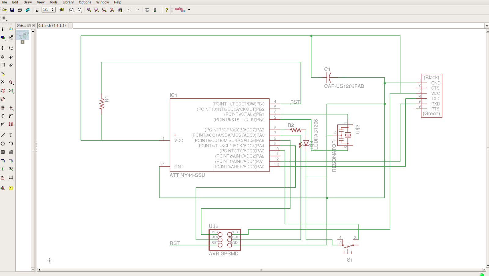
LED Blinking
First programme I done was that to blink the LED with a time delay of 1s.
  #include < avr/io.h >       // Importing the avr/io library (as stdio.h in the normal C)
  #define F_CPU 20000000      //telling the frequency, here the 20Mhz of the Resonator
  #include < util/delay.h >       // Importing library for  delay (For blinking LEDs we need delay)

  int main(void)
  {
    DDRA = 0b00000100;       //Set Pin PA2 on PORT A as output

      while(1)
      {
      PORTA = PORTA | (0b00000100); //PA2 is 3 from left

      _delay_ms(1000);          // delay of 1 second

      PORTA=(0x00);            // Make all pins in port A low

      _delay_ms(1000);         // delay of 1 second
    }
  }
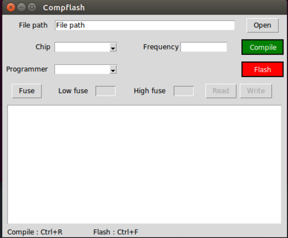
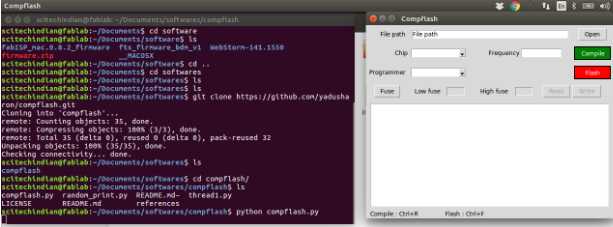
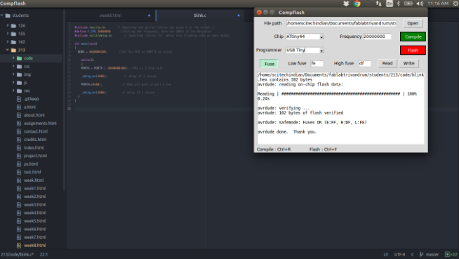
To compile this programme, I installed compflash which is developed by one of our instructors, Mr.Yadu which is an user interface in python language for easy compiling and flashing. For compiling and flashing the programme, we are instructed to open the terminal and type python compflash.py. Then user interface will be get opened.
Download the Program file blink.c
LED Control using Switch
#define F_CPU 20000000    // defining CPU speed as 20MHz
#include < avr/io.h>    // Importing avr/io library
#include < util/delay.h>  //Importing delay library
int main(void)
{
DDRA=0xF7;      //Setting the DDRA register with 0b11110111(enabling PA3 as input)
PORTA|=(0b00001000);    // Pulling Port PA3 to logic High(Switch)
PORTA&=(0b01111111);    // Setting the LED (connected to PA7) permenantly OFF
while(1)
{
if (!(PINA & (1<<3)))    // Checking for Switch press
 {
PORTA|=(0b10000000);    // Writing PortA- pin PA7 to logic high (LED ON )
}
else
{
PORTA&=(0b00001000);    //Set PortA pin PA3 as logic high(pulling up)
}
}
}
I set Port A, PA3 as input port as I have connected switch in PA3. I wrote the hex value of 0XF7 which is equivalent to binary 11110111. On the other hand I turned of PA7 to turn off the LED. Here the pin will be in floating condition and LED will ne ON/OFF in between.
Next I need to check the condition for switch press. For that, I used If loop where Port A data will be read and to logical AND with XXXX1XXX. Then taking compliment of it. Now if we press the key, the condition will be logic high and programme enters into the loop and write logic high to PortA PA7 so that the LED will be turned ON. On the other hand, LED will be in off state and pulling up the PortA-PA3.
Then I compiled the programme as I mentioned above
Download the Program file switch.c
Go back HOME