Week 8: Computer-Controlled Machining
Group assignment:Test runout, alignment, speeds, feeds, and toolpaths for your machine
Individual assignment:Make something big
Computer Controlled Cutting
CNC router (Or Computer Numerical Control router) is a computer-controlled cutting machine in which tool-holding head whose movements are controlled by the computer.CNC stands for Computer Numeric Control it is a process used in the manufacturing sector that involves the use of computers to control machine tools.Informations are taken from this source
Process that involves in computer controlled cutting is first we need to create a cumpter aided design file ( CAD) . After Design the CAD file we use CAM ( Computer aided manufacturing )software to convert CAD file to Computer understandable code name G-CODE.
G-Code is essential thing for the operation of CNC machine, in every G_CODe which tells machine where to move, how fast to move, and what path to follow. With a 3-axis CNC machine, the computer tells the head to "move in the X axis 100mm"... "move in the Y axis 130mm"......."move in the Z axis 100mm"... etc.
This week we are familarized with Shopbot ,large format CNC machine which can be used to cut timber, plywood, soft aluminum etc.I see a instructables class which explain about using of shopbot.I used this as the tutorial for learning more about designing work in fusion 360 and more about cutting in shopbot :Instructable page I refered
Shopbot Alpha
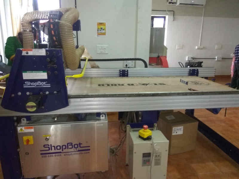
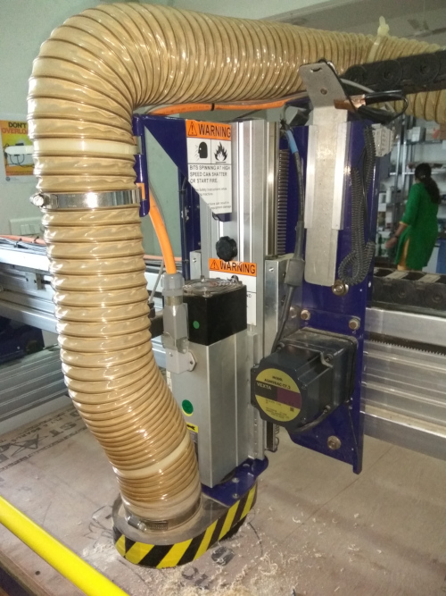
In our lab we have Shopbot alpha 96 48 , which can handle 4’x8’ sheet goods.
Tools used
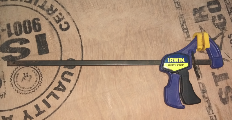
- Clamps for Work-holding and Assembly: These are used for Holding the work piece in bed
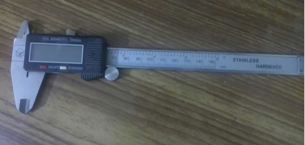
- Digital Calipers: Used to take measurement of Material
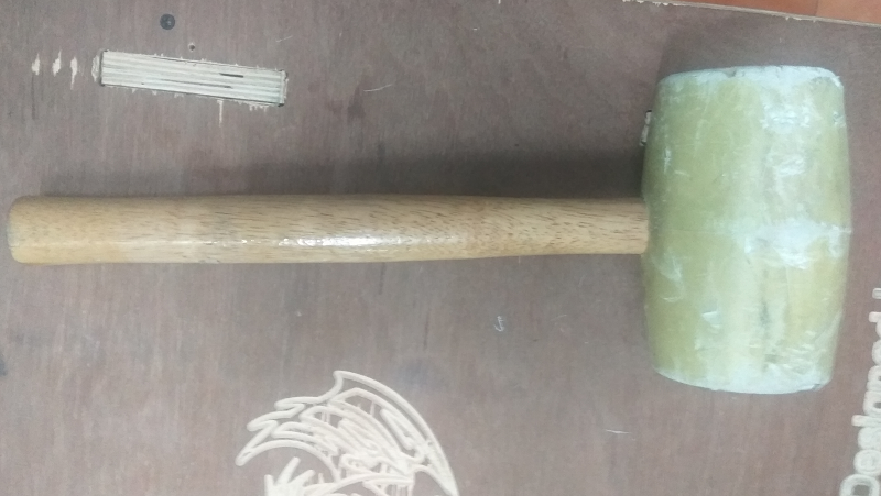
- Hammer: Used for Assembling the parts
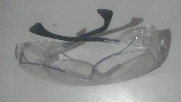
- SAFETY GLASSES: Protect eye from Dust particle while perfomming cutting operations
- EarMuff : Protect ear from the high intensity noise generated by machine while operation.
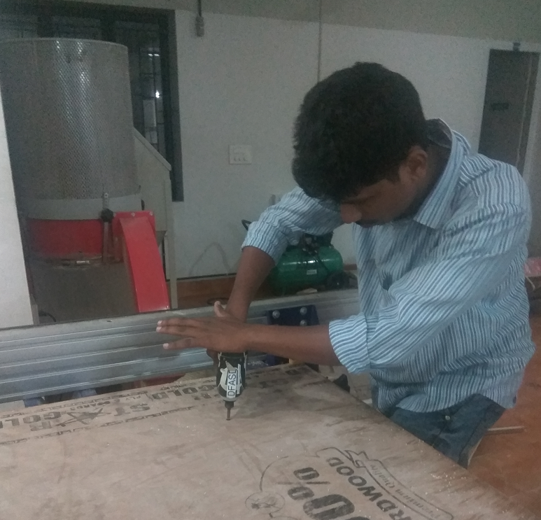
- Driller : Used to drill and fit the screws in Material
- EndMill: An end mill is a kind of router bit with properties that make it better at cutting for specific applications.

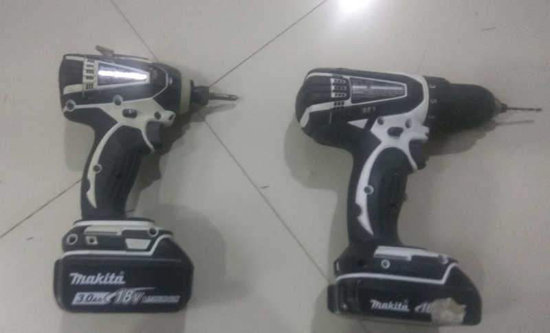
EndMill and DrillBit
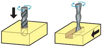
Both of them are looks similar and they are designed for differnt purpose.Drill bits are designed to plunge directly into material, cutting axially and creating cylindrical holes.End mills are typically used for horizontal carving and cut laterally
Details are taken from the makezine article
End Mills
To make a tool path to make cutting of material , we have to know which end mill is good to use
Shaft Diameter: The shaft diameter describes the width of the cut made by the end mill.
Flute: The flute is the sharp edge of the end mill. An end mill commonly has one, two, or four flutes. Flutes can be straight, meaning they're parallel to the length of the end mill shaft, or they can have a spiral profile along the length of the shaft.
Profile: The profile of the end mill is the shape of the profile of the bit looking at it from the side. There are many different kinds of profiles, but the most common are ball-nose and flat.
Above details are from Rahul S rajan fab documentation
Cut Direction: There are upcut, downcut, and compression cut end mills
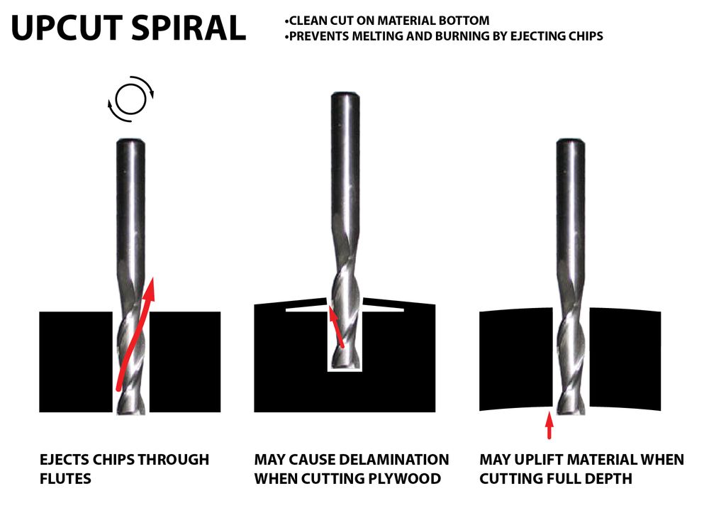
In an Upcut type end mill the teeth on the flute will point upwards. This means that the end mill is cutting and drawing out the wood through the flute. This is good for cutting deep into the stock. But this leaves a bad surface finish on the top of the surface.
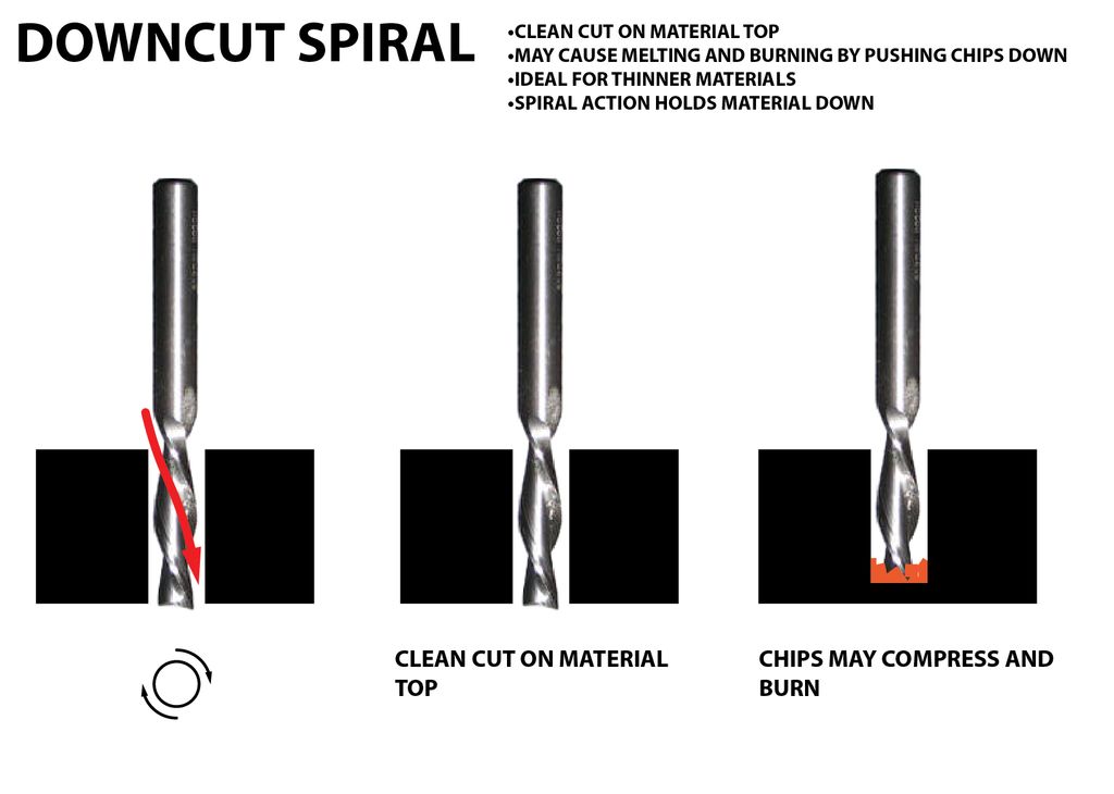
A downcut type end mill has teeths that point downward on the flute. This means that the end mill will cut and try to push the material into the stock. This will give good surface finish on the top, but it is not very efficient at removing material.
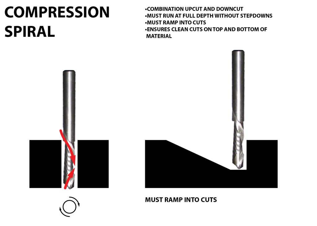
Compression spiral bits are a combination of upcut and downcut bits. The lower third of the bit has an upcut orientation, and the upper two thirds have a downcut orientation. This end mill results in clean cuts on the top and bottom of the material while avoiding the burning and lifting issues of downcut and upcut bits.
Chip load : This is the amount of material that is removed in each chip. The value is approximately = feed rate (inches per minute) / (RPM x number of flutes)
Cut depth : This is the measure of how deep the end mill should go in each step while milling. Ideally cut depths should be less than 1/3rd of the length of the tool. They are mentioned in the product manual of the tool bits.
Details are taken from Instructable page
How to Cut with Shopbot
Shopbot runs on a series of commands called G-Code.These commands tell tool head where to move, how fast to move and what to cut.
This is usually the first step we have to design what we are going to cut. For cutting, we need a 2D vector path of the part. Design the cutting part and export it as the .DXF file which can be used by Vcarve. I used fusion 360 for designing the path and Rhino for some light modifications as it is easier to edit DXF files in Rhino. Once the CAD design did now, we can move on to the CAM setup.
For controlling shopbot, we need to generate a G-code file from the CAD, to do that we need a CAM software. We use Vcarve for generating the shopbot file from the CAD design.
My Design
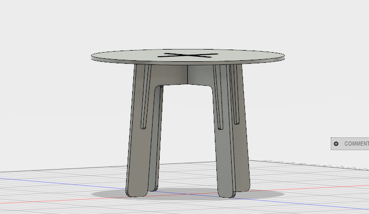
From starting off this week, I am the little bit confused about what to make. For me its hard to find something, what I did is the plan to learn how to use shopbot, and fusion, I found a tutorial in the Instructable page that shows designing and making a table using fusion 360 and shopbot. I decided to choose that and design my self by referring to the tutorial made by them. The length and other parameters are given to my design is different compared to their.
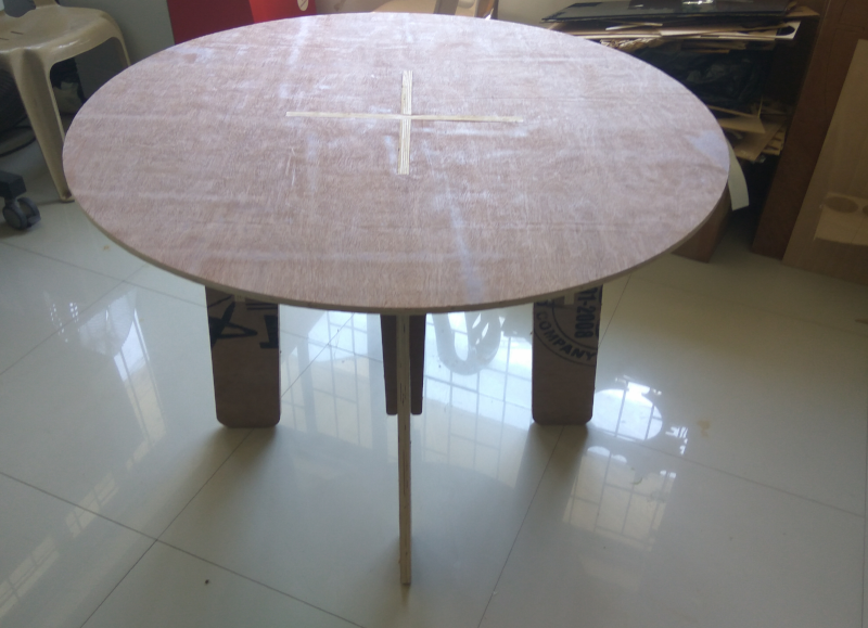
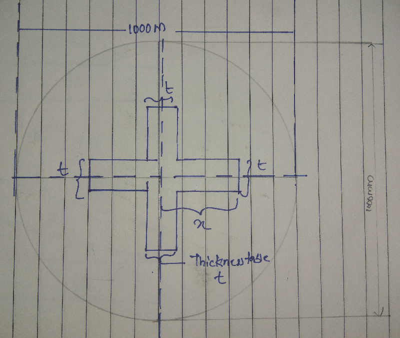
I want to make a small round table for conducting two person meeting. The height of Table is about 700mm and width is about 1000mm. I decided to design the table a frictionally fitted one,friction-fit means it can be assembled so that the friction between the pieces will hold it together without any fasteners.
Before going to design i made some rouf drawing of legs,tabletop and stiffeners. First I go with Design of the Table Leg.the go with table top and stiffeners
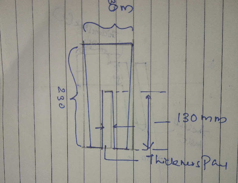
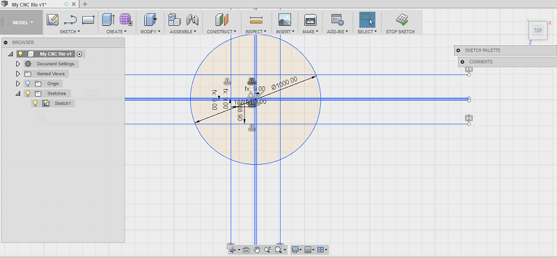
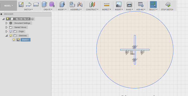
Before that I used fusion 360 to design the table , first set the tickness of table as parametric , beacause from manufacture to manufacture thickness get varies
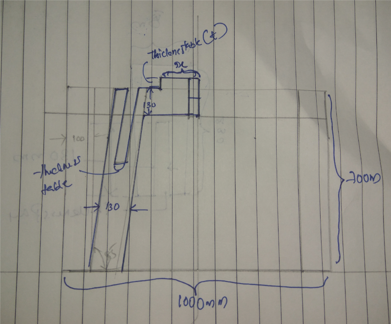
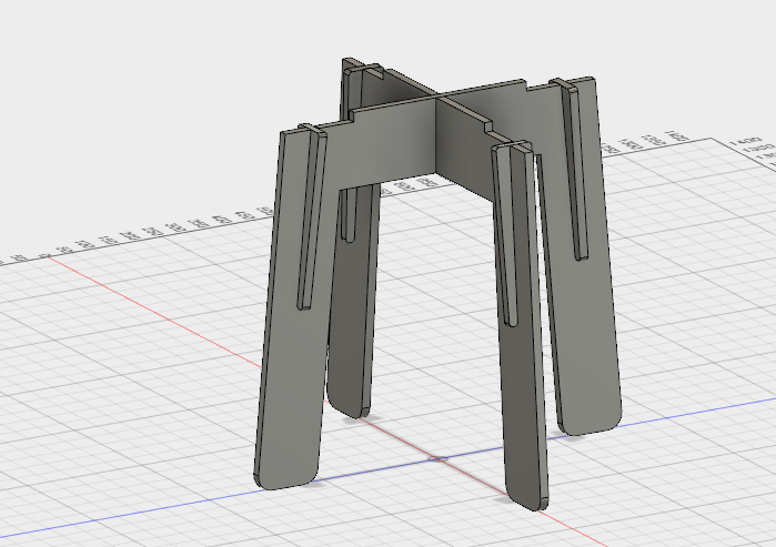
First start with legs
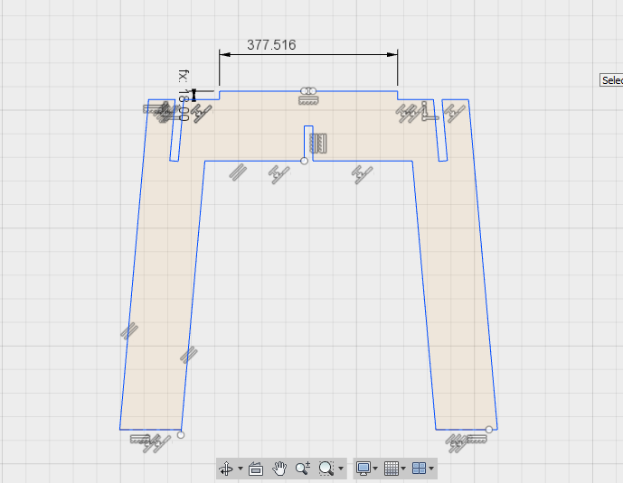
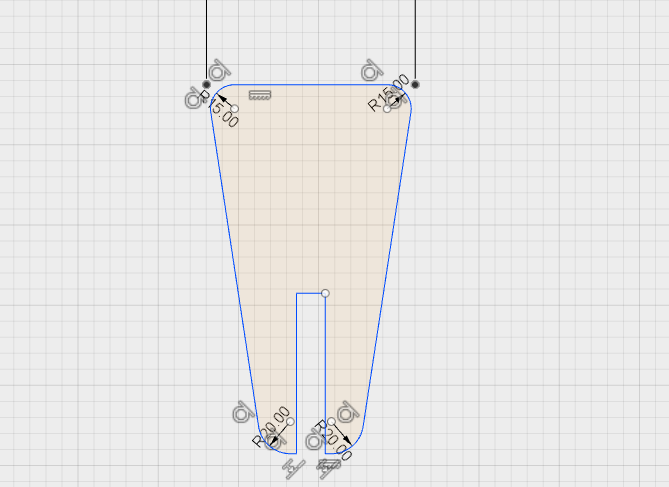
First i draw a box of 1000mm to 700mm , in which table top is of 1000mm length and height of 700mm.Then add the press fit construction in top of leg and also draw pockets to fit Stiifer.I choose the width fo leg is 130mm
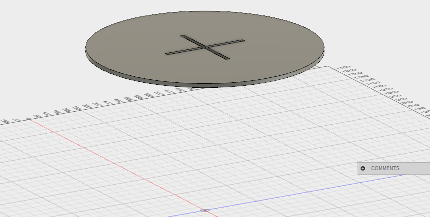
After Design the legs i measure the press fit in top of leg, i need it fit in the center of table , so i made pockets in table depends on that measurement
AFter that i design stiffiner for the table , with out stiffiner the table will twisting motion if we push on the tabletop.
3D Model of Table parts
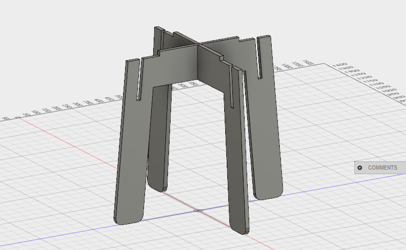
By referring to the Instructables tutorial, I learn so many functions in fusion 360, its well-documented one and now I am good in fusion 360 also. I decided to use fusion 360 for the Final project, I already try fusion, Solidworks, inventor and Rhino. My laptop has only minimum requirements, so I planned to go with fusion on my notebook and SolidWorks on my PC.
After design the CAD file i export the dxf file from fusion 360 and open it in cad to arrange the design.After arranging then i need to make it cut so , i used another software name V-curve to Create G-CODE
Group Assignment
First, we did the group assignment to characterise the machine. Akhila and Rinoy do drawings for test operations.We milled a few square shapes with varying parameters for cutting, feed and speed. Toolpaths generated for each square. The configurations with the same tool speed (in rpm) can group, even if they have different depths and speed.

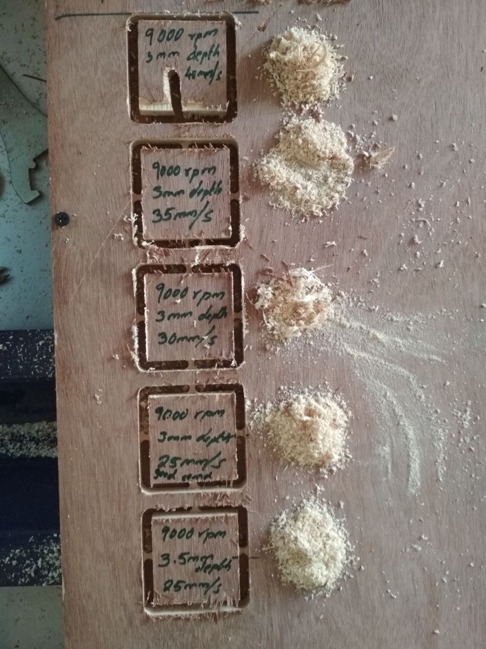

The quality of cutting deteriorated when both spindle rotation speed and depth decreased. It is best at 12000rpm and 3mm depth, 35mm/s speed. For the same rate, at 6000rpm and 2mm depth, the tool loosened.
At 12000rpm, we heard a high-frequency sound, especially at higher speeds. It seemed to us that the best cutting quality (+good chip texture+good sound) obtained with the following parameters: 9000rpm spindle speed, 3mm cut depth and 25mm/s tool speed.
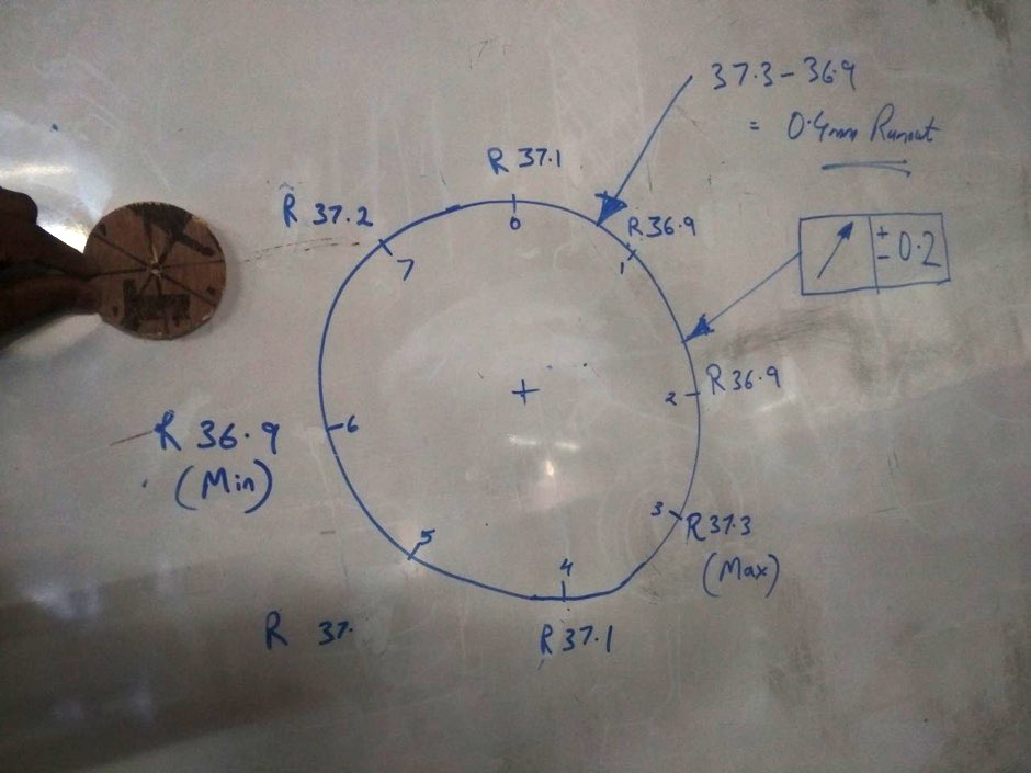
The radius of the circle measured at different points throughout the circumference. Half of the difference between the maximum and minimum values gives the value of the tool run-out. We measured : 37.3 - 36.9 = 0.4mm; Run-out= +/- 0.2mm
Using Shopbot
I am planning to make a table (idea copied from link) by using 18mm plywood, so when i check the inventory we only have a single piece of 18mm sheet, but two of my friends also need some part of 18mm so i desided to cut my table top in 12 mm,one of my firend uctted only have of 12mm plywood , its already on the shopbot bed so i dont need to fix it.
I Export table top file from fusion360 as step format and then open it in inventor and export table top in dxf file.For making the g-code we use v-curve software by shopbot.We use Windows for using v-curve there is no linux version for it.
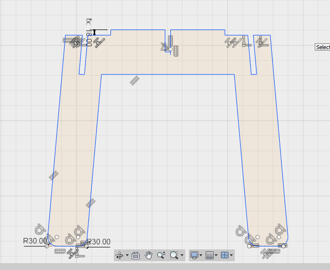
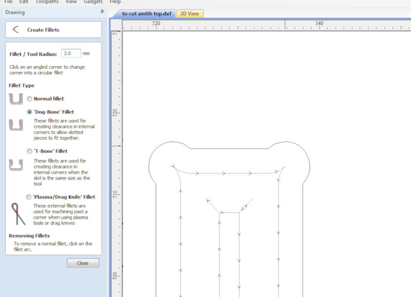
If we have squares in design file we need to make some modifications in design file ,Our bit is round so if it goes outside the cutpath we dont get 90degree cut its just a circle cut only so we put some holes in the plcae of 90degree cutting we can get perfect edge cut. We can use differnt types of fillet , i choose 3mm holes with dog-bone fillet type.
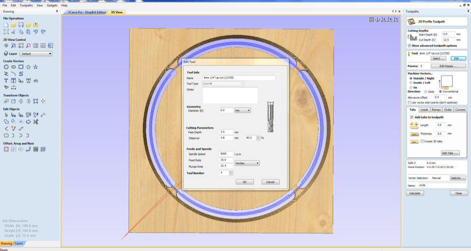
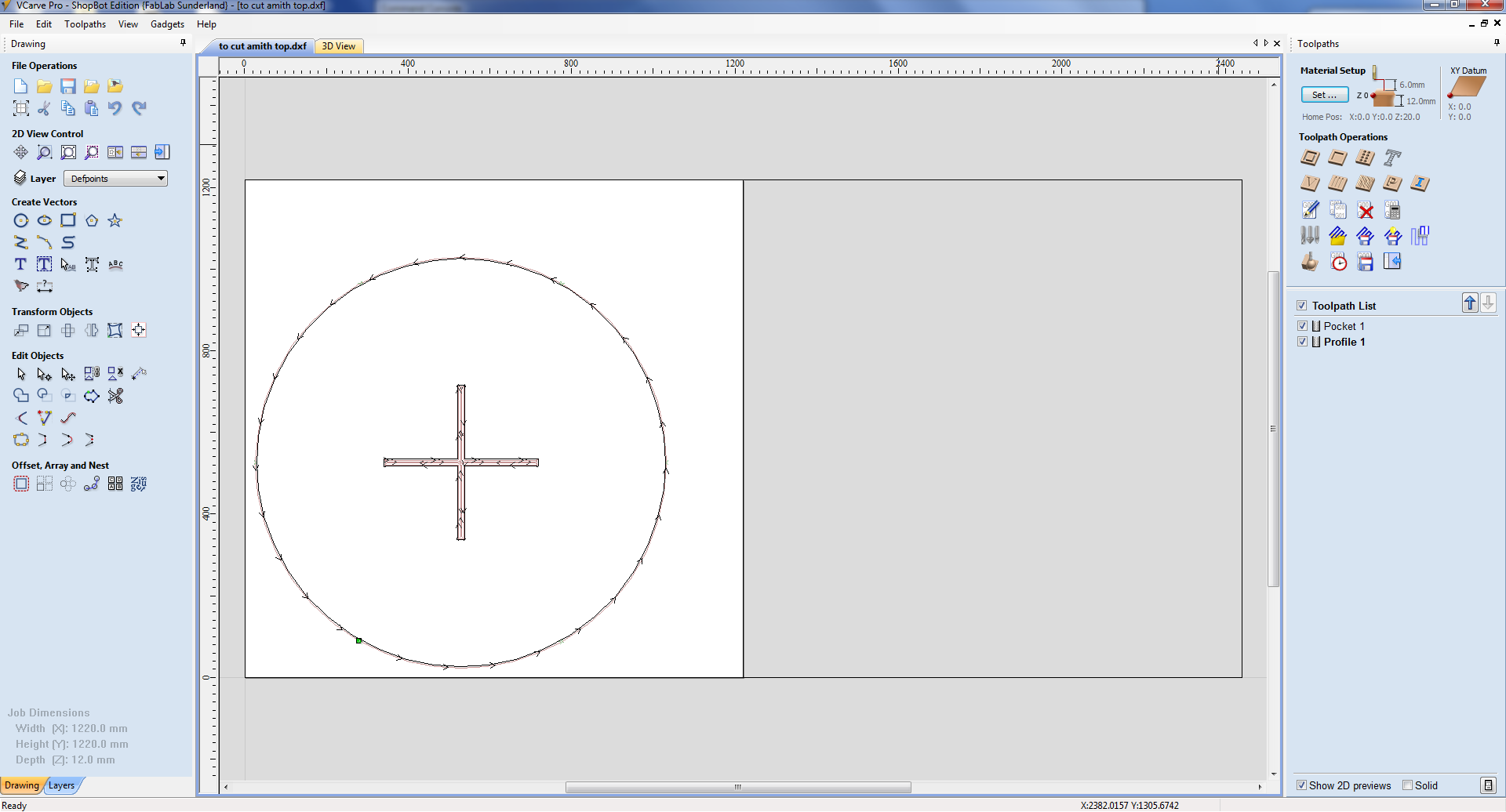
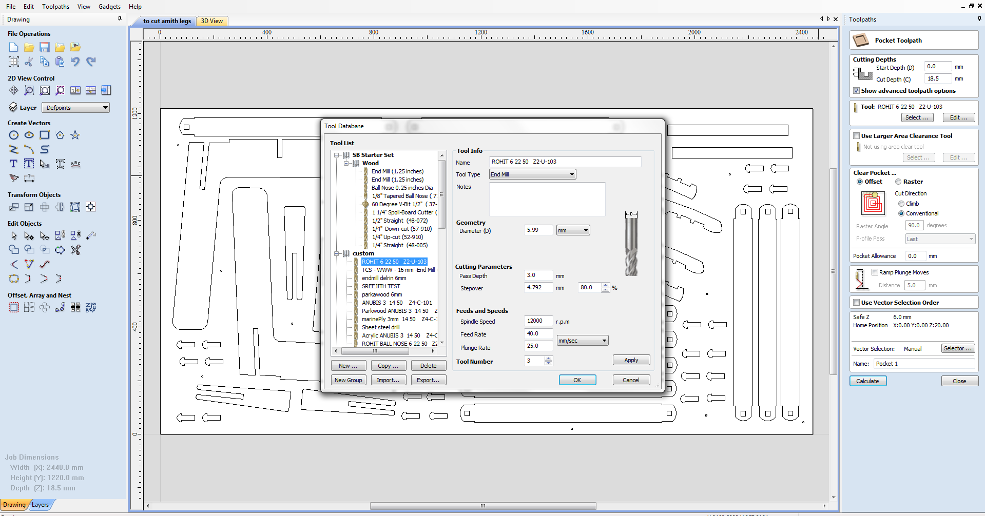
After save the paths for drill then select design for cutting and choose the tool path operations
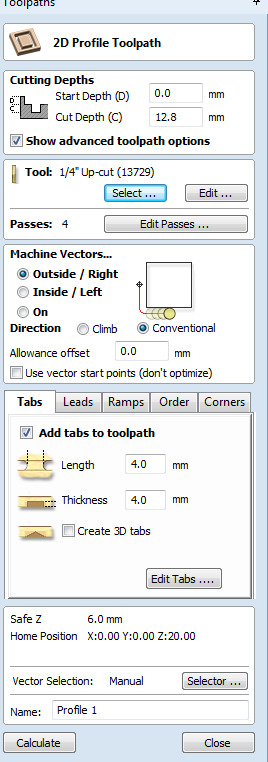
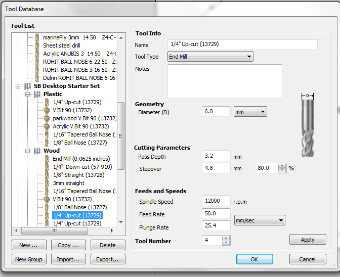
Select tool and apply the parameters like speed, pass depth etc.
Next save the files as .sbp format and open the shopbot software,The shopbot software is the software which drives the machine. There are many control options. We can position the head anywhere in the bed by using the options. FOr setting the origine, first we need to set the X and Y axes. Once we move the head to the XY origin we can set the X and Y axes as zero.For that, click on zero axes, check X and Y then click Zero.
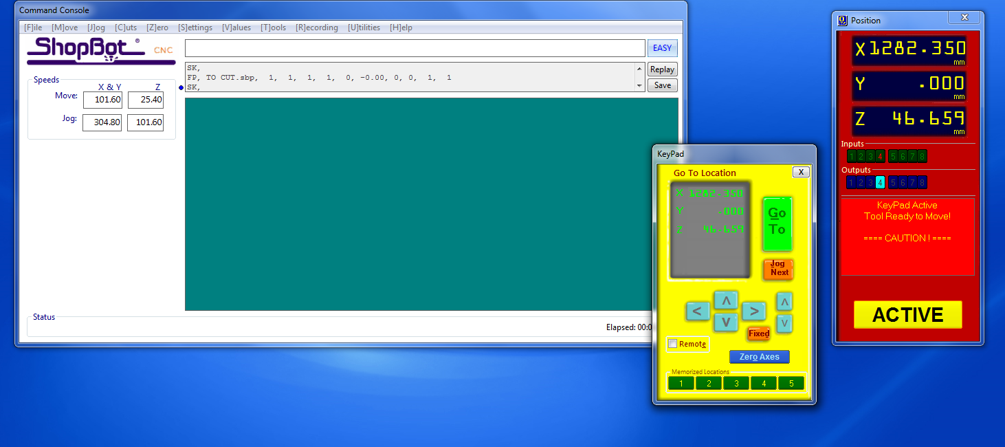
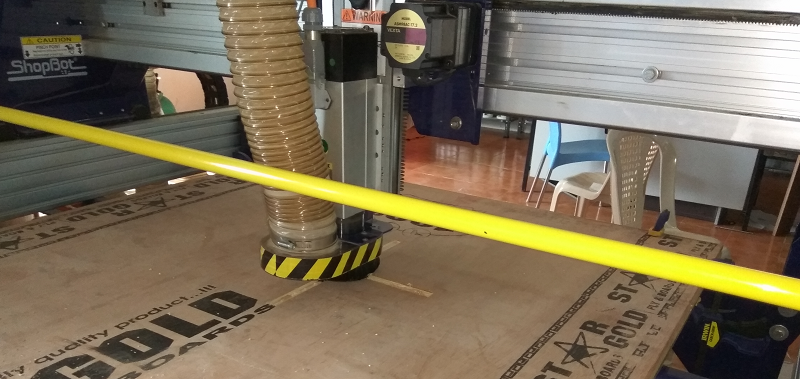
For setting the z axis we have a dedicated option, aplate and clip on shopbot,plate on the plywood under the drill bit, then put the clip on the drill bit click Z Button . it will move downwards till the bit touches the plate.this processs will repat two times and finally z axis also set.then load the cut part, CLick on "start". Press the green button to start the spindle. And press "Ok". Now the machine will start cutting.
After cutting the table top i remove the matrial from shopbot clean surface and bed of shopbot and then load 18mm sheet.In order to reduce the material wastage ,me Akhil hari and Vishnu combine all our design files in to a singel dxf file and put it on the v-curve, first we put some drills to fit the plywood with the bed

To save material, Me, Akhil and Vishnu were using the same plywood for cutting our design. My parts arranged very tightly and the parent material left after the cut was to have several narrow strips. These thin strips were expected to vibrate and break during the operation, putting the bit at the risk of breaking. To avoid the possible breaking of the bit, tabs were used in plenty, and the parent material did not vibrate as expected. However, after the operation, it was later realised that the tabs provided were more than what was required. Due to a large number of tabs provided, the parts were trying to remove and also the tabs portions had to be manually filed down to obtain a smooth finish. had First, we go with my design, and I gave 4x4mm tabs because of we firmly packed the pieces

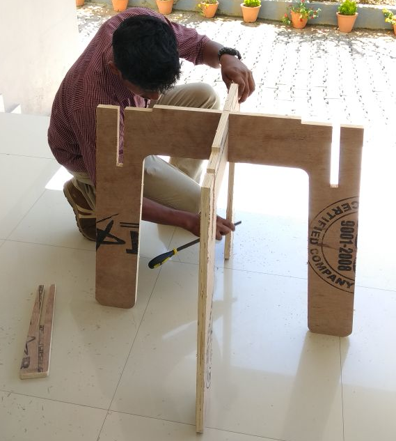
After performing the cutting i got my table legs , stiffner then i assemble the table