Week 6: 3D Scanning and Printing
Group assignment: test the design rules for your 3D printer(s)
Individual assignment: - design and 3D print an object (small, few cm) that could not be made subtractively - 3D scan an object (and optionally print it)
3D Printing:
3D printing is a process of making three dimensional solid objects from a digital file. Idea behind 3D printing is came from the additive process while doing the creation of houses, laying of bricks layer by layer. In 3D printing layers be a thinly sliced horizontal cross-section of the eventual object.
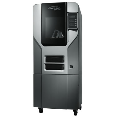
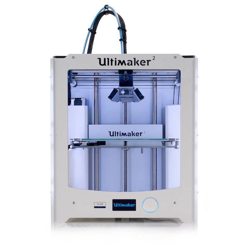
3D printing is the opposite of subtractive manufacturing in which cutting out a piece of metal or plastic with for instance a milling machine. In Our lab we have two available 3D printers.one is Dimension 1200 and other is Ultimaker 2. Here we use Ultimaker 2 for our 3D printing.
Ultimaker 2 – Design Rules
Ultimaker 2 is one of the most accurate and reliable 3D printer, In which it is supported by a large number of material named PLA, ABS, CPE, CPE+, PC, Nylon, TPU 95A, and PP. We are using PLA for our modeling. PLA is a biodegradable and bioactive thermoplastic aliphatic polyester derived from renewable resources, such as corn starch , cassava roots, chips or starch, details are copied from this link click here to know more. Nozzle temperature of 3D printer should be a range of 190 to 240 degree Celsius.
How we use Ultimaker 2
Once you have the design file in STL format open it in CURA software, CURA is the 3D printing software, which is used to create the G code.
Choose the machine as Ultimaker 2, give settings (we use temperature as 230 degrees Celsius) Save the file as G-Code and save this to SD Card .Load Ultimaker with material.
Put Sd card in Ultimaker and use the scroll button to required settings and check that.After that just print.
Note: During removal of material Nozzle should be preheated, even after completed every printing material should be removed and cut the tips of material. Our area has high humidity, so we need to keep material in a box after printing, PLA is easily absorbing the moisture and it gets damaged.
Testing the limitations of 3D printer
To check the limits of our 3D printer we decided to print a test piece . Its layer height measures one of the main parameters we need to find the resolution, The resolution of a 3D printer. When resolution becomes lower 3D printing quality will be high. We have downloaded a test print model from Thingiverse and is shown below with the test parameters.
Test files is downloaded from the Thingiverse website : and ctrlV files are licensed under the Creative Commons - Attribution - No Derivatives license.
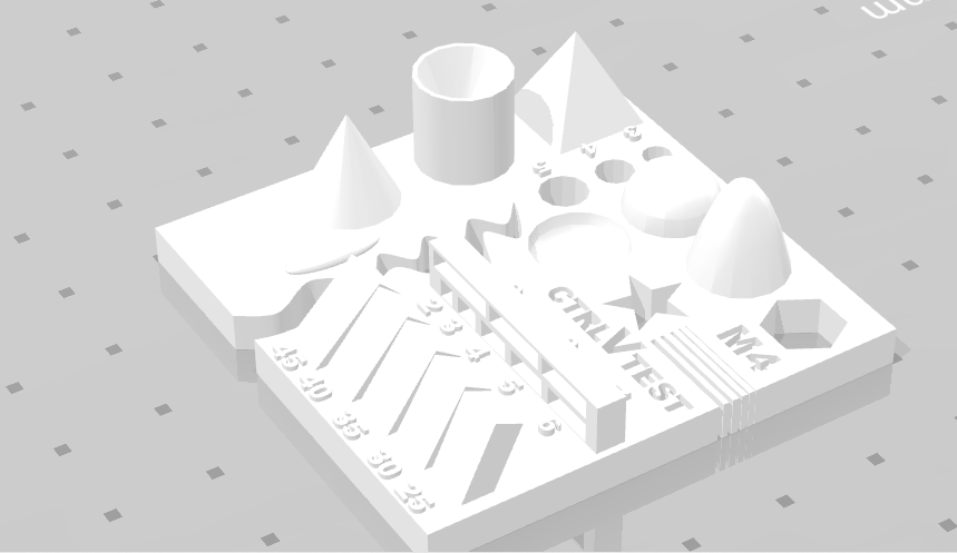
- size: the object is 2x50x30mm (baseplate)
- hole size: 3 holes (3/4/5mm)
- Nut size: M4 Nut should fit perfectly
- fine details: pyramide, cone, all numbers
- rounded print: wave, half sphere
- minimum distance & walls: 0.1/0.2/0.3/0.4/0.5/0.6/0.7mm
- overhang: 25°/30°/35°/40°/45°
- bridge print: 2/3/4/5/6/mm
- surface: all the flat parts
Test Print Settings
Some Important Parameters you need to know before 3D printing a model. 3D printing is an additive manufacturing method so while we go to 3D printer for printing some model we need to know some parameters before generating g-code
Layer Height: In 3D printing processes build parts layer-by-layer, so the resolution of the model we printed depends on the thickness of the layer. Layer height should be low as the quality of model printed from the printer is good.
Shell Thickness: 3D printed model is divided into two few different areas, mainly outer shell and inner shell. The infill is printed in a cross-hatch pattern and attaches to the outer shell with a slight overlap to ensure the lines fuse together for a stable print. Increasing the wall thickness to two or more multiples of your nozzle size A thicker wall has the added benefit of making your parts much much stronger.
Infill percentage: The strength of the design is directly related to infill percentage. A part with 50% infill compared to 25% is typically 25% stronger while a shift from 50% to 75% increases part strength by around 10%. Where a 3D printed part is going to be drilled or screwed infill percentage becomes a significant factor.
Details are taken from these links : link1 link2
After Downloading the Test STL, We open the STL on cura Software. Nozzle diameter fo ultimaker is 0.4mm, Settings in cura given as Nozzle diameter 0.4mm, "Brim" type platform Adhesion and with no supports. Layer Height of 0.08mm, Shell Thickness of 0.8mm, Bottom/Top Thickness of 0.8mm, 35% Fill Density and 50 mm/s print Speed After that cura shows 1Hr and 54Min to print. The nozzle temperature set to 240 degree Celsius and base plate temperature setted at 80-degree Celsius.
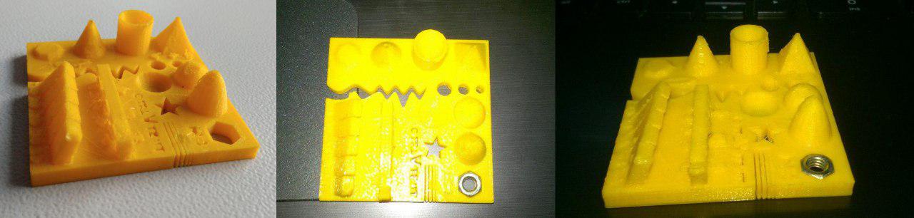
After test printing model looks good , The diameter of holes was slightly less. The M4 nut was fitting perfectly, with the pyramid and cone having the perfect surface finish. Bridges didn't come out well without the supports.
My experiment
For me I need to design a object that should not be make using substantively choose to make a gyro uing three circles that rotated in 3 different axis. Before drawing I made some drawings.
I plan to design a gyroscope, the gyroscope is device consisting of wheels or disk that mounted so that that can spin rapidly about an axis which is itself free to alter in direction. Our design must be a model that we cannot make it subtractively.
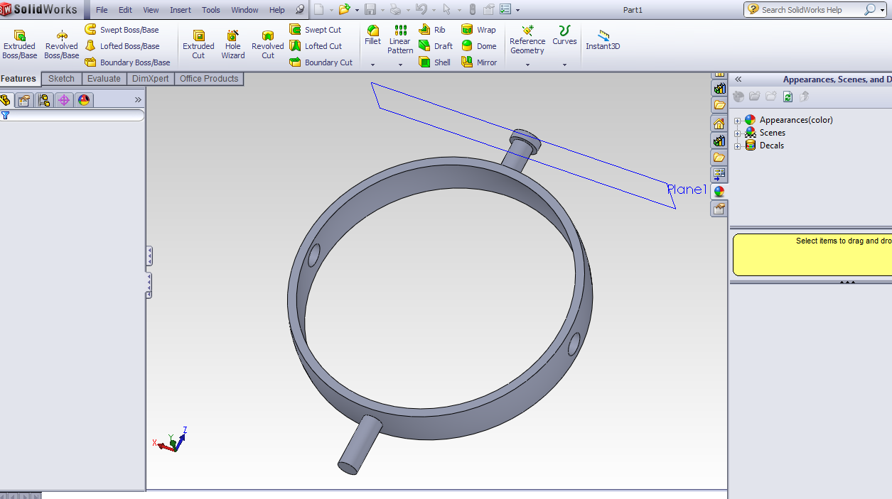
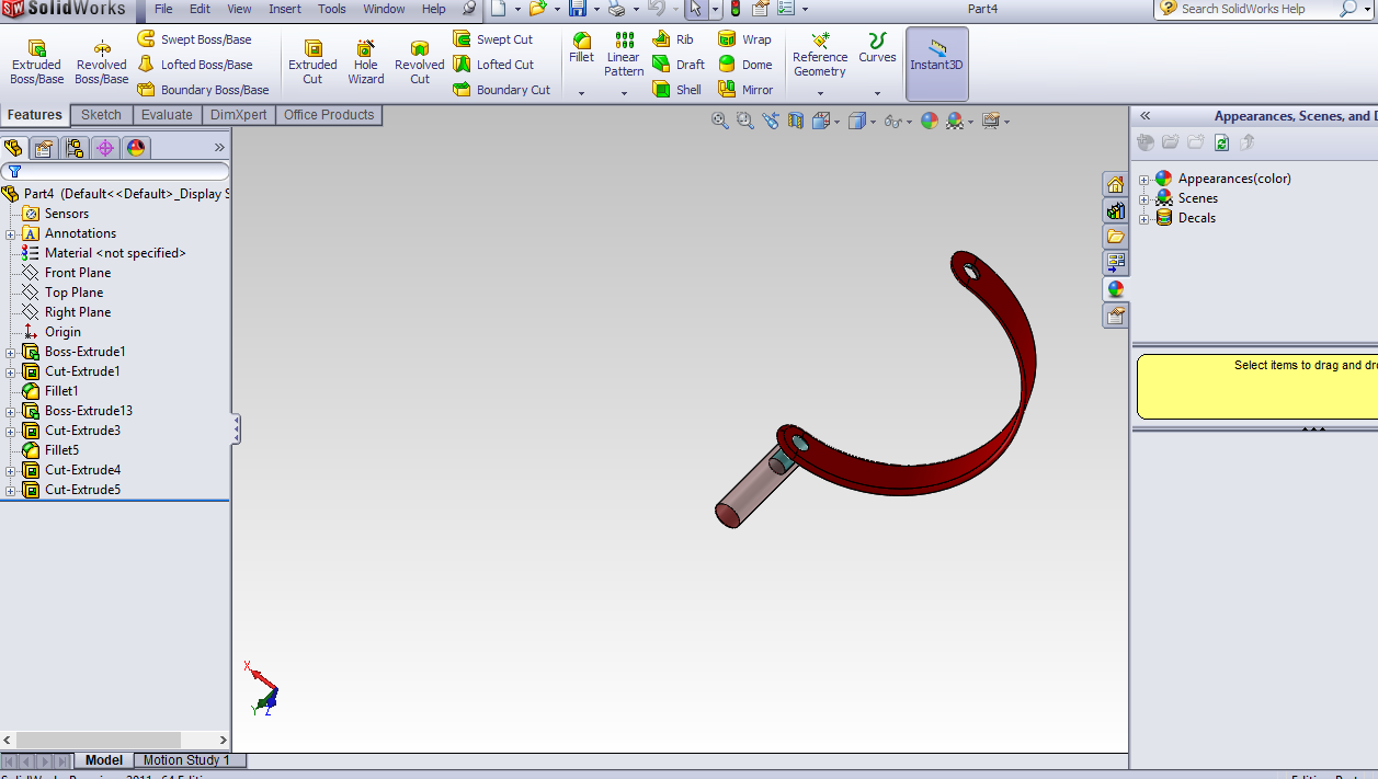
So I decided to start with the design the wheels of the gyro in part by part and then do assemble inside the software. I use SolidWorks for designing purpose. My gyro have three wheels and a holder. First I start with outer wheel.
After opening the solid works I choose the front plane and then draw two arcs of different radius ( 47mm and 50mm) in the front plane then join the end point of arcs. After that, I performed revolve function by choosing the y-axis hence we got the wheel (shape looks like traditional Indian bangle). next, we need two legs to attach with holder and also need two holes to attach the other wheels.
Next I need to create hole on wheel. So I draw a circle of 8mm diameter on the right plane. After that, I perform the cut function. Entire cut correctly passes through curve structure of wheel( if we cut the wheel across the holes we can get two equal parts ) Then I draw a plane parallel to the front plane at the height of 62mm then I draw a circle of 8mm and extrude and join it to the wheel. After drawing the one leg from the plane I created, next, I mirrored the entire leg by considering front plane as the axis after that I got two legs in the wheel. Next, I design end stopper on one of the wheels to prevent it from pulling out from the holder.
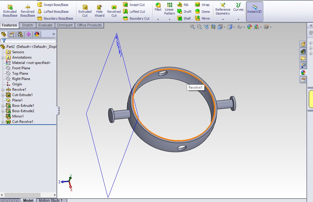
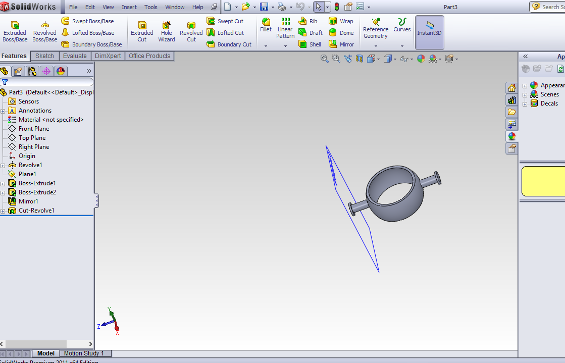
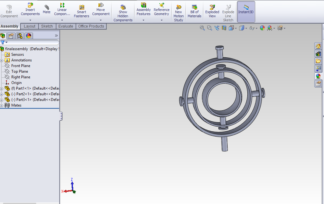
Similar procedures are followed for all the parts. But radius of the arcs are different one wheel is rotating inside the other, so its radius is comparatively smaller to the outer one.
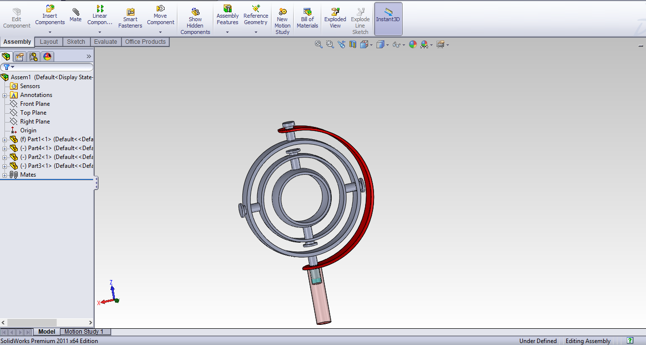
Next is the most complicated work is assembling all the parts inside the software. First I open the assembler and then open the stand because by default first part always be fixed. Then open the part 1 and choose mate function and select the outer surface of the leg with stopper and also select the inner surface of the hole ( hole at the top of stand) and Next select outer surface of part 1 and the inner surface of stand make the concentric relation. After that, I can see that wheel (part 1) rotating. The similar procedure done for other parts and finally, I can get the 3D model of the gyroscope.
Open the STL format in cura software , set the machine parameters and save the G code in sd Card.
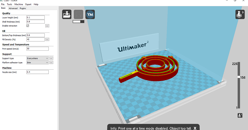
After saving gcode, open that in ultimaker and perform 3D printing. Finally i got the model of my gyro.
This can't be done by subtractivley.wheels are placed one over other in which there is stopper on each wheels to lockd in there position
3D scanning
We need to make a 3D scan model in this week so we use Kinect sensor for performing the 3D scanning.
Kinect
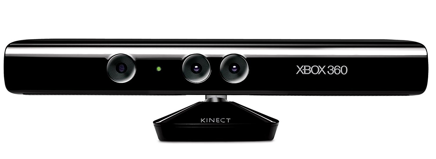
Kinect is a line of motion sensing input devices developed by Microsoft. The Kinect contains three important parts that work together to detect your motion and create your physical image on the screen: an RGB color VGA video camera, a depth sensor, and a multi-array microphone.
The camera detects the red, green, and blue colour components as well as body-type and facial features. It has a pixel resolution of 640x480 and a frame rate of 30 fps.
The depth sensor contains a monochrome CMOS sensor and infrared projector that help create the 3D imagery throughout the room. It also measures the distance of each point of the player's body by transmitting invisible near-infrared light and measuring its "time of flight" after it reflects off the objects.
The microphone is an array of four microphones that can isolate the voices of the player from other background noises allowing players to use their voices as an added control feature.
These components come together to detect and track 48 different points on each player's body and repeats 30 times every second.
Informations and content are taken from wikipedia Refer this website
My work
We installed the drivers for Kinect and supporting software in Fab lab PC itself .we use Reconstructme software for 3D scanning. ReconstructMe’s usage concept is similar to that of an ordinary video camera – move around the object to be modelled in 3D. Scanning with ReconstructMe scales from smaller objects such as human faces up to entire rooms and runs on commodity computer hardware.
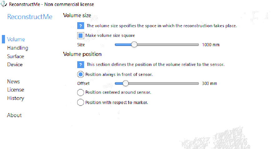
Open Reconstruct me and choose the volume here it shows the size we want to perform the scan.
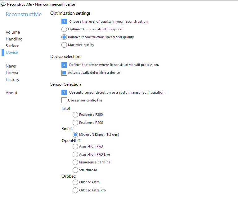
Then we choose the device and select Kinect sensor and click the setup complete
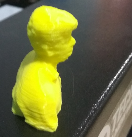
After we start the scan, I placed in a chair, and one of my colleges rotates me. finally, we got a good 3D scan of me.
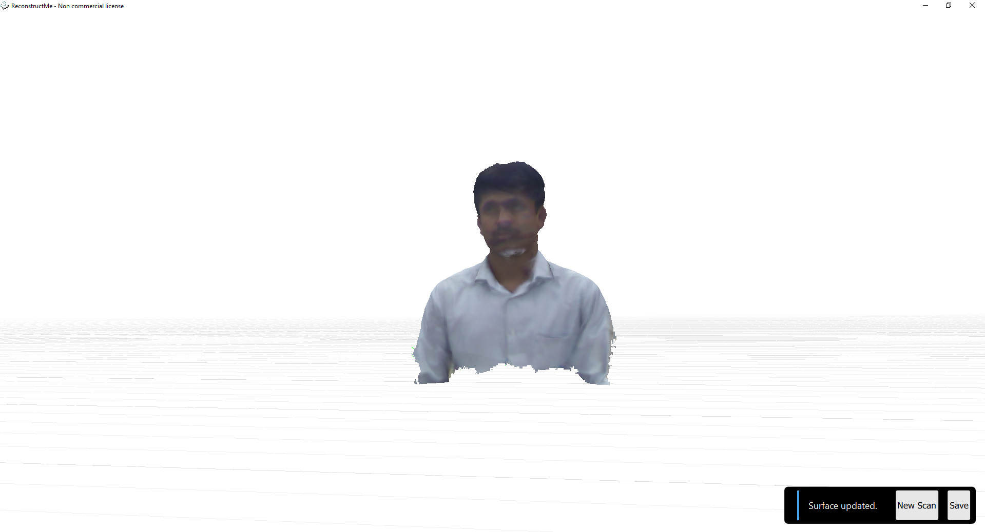
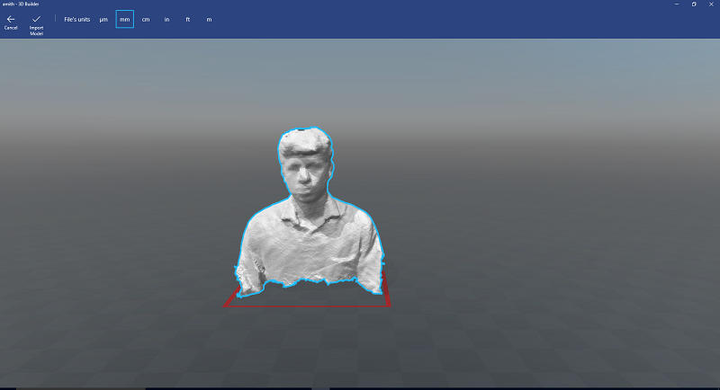
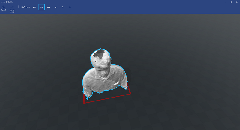
After scanning save it as STL format, open that in windows 3D builder app and then I see that some holes in my head and bottom.
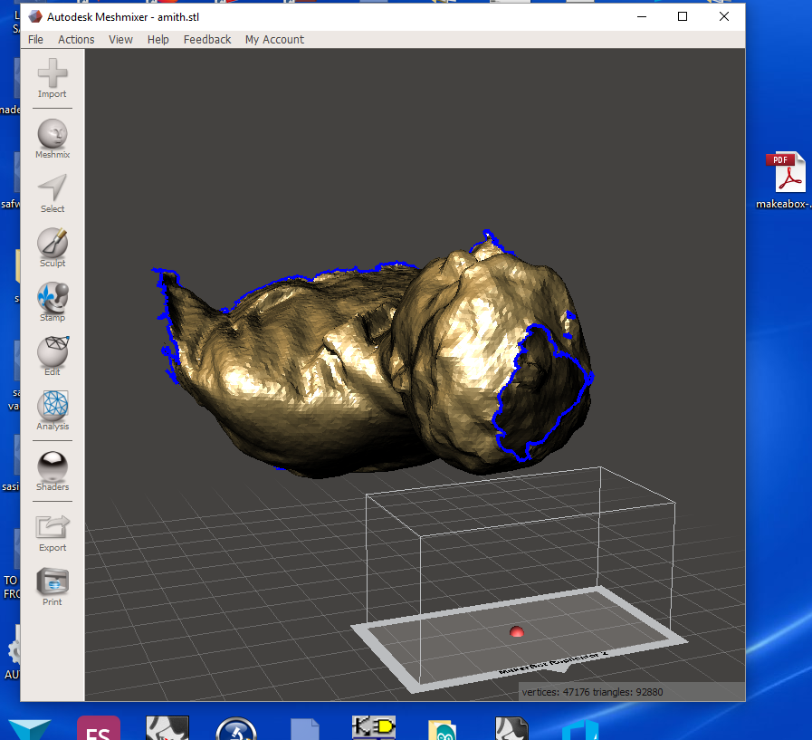
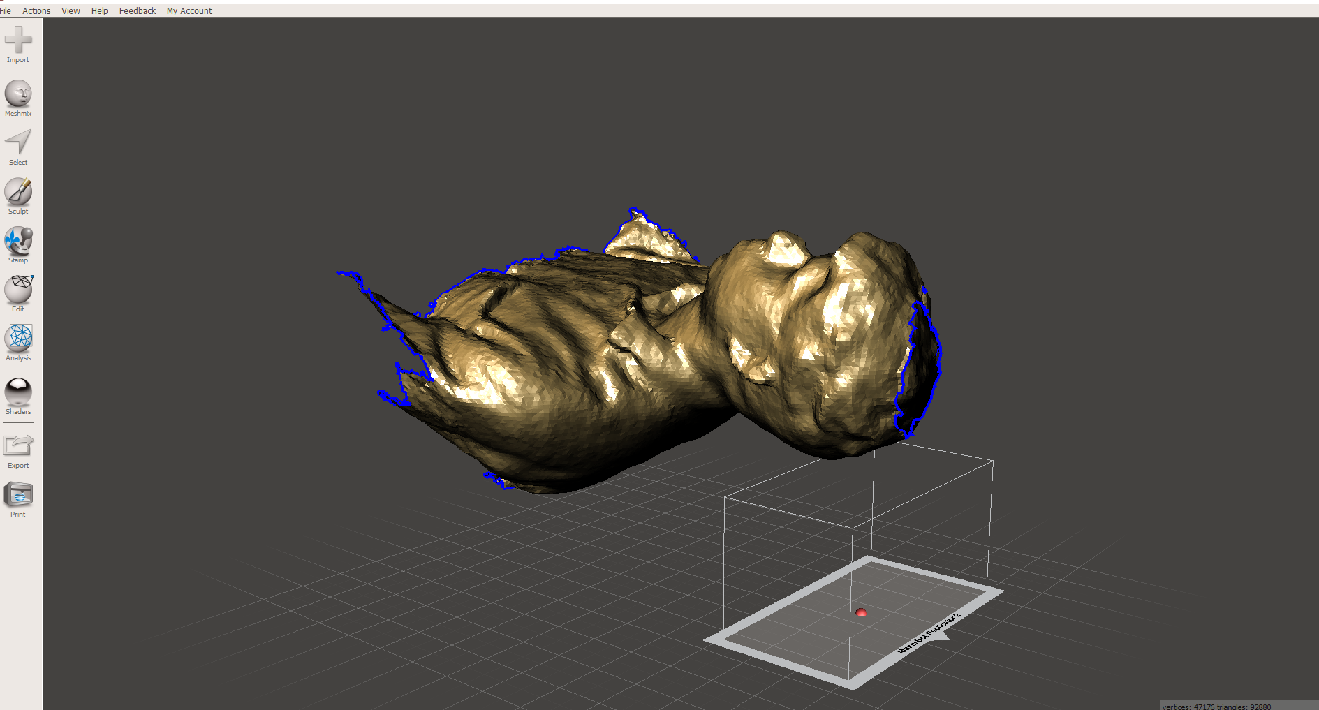
To fill I Open that in Autodesk mesh maker.After solid fill in mesh maker , I also do some finishing touch.
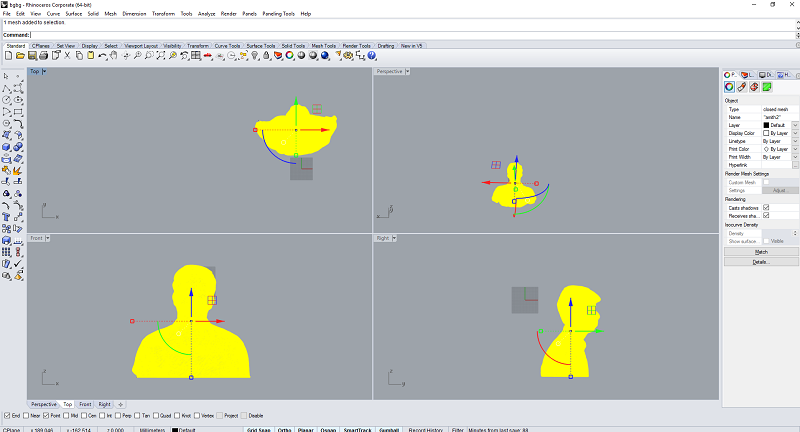
Then save as STL. But the file is large so Open it in Rhinoceros and using scale down command to reduce the size and scale it to small size.
After export as STL , I open this in cura and save the gcode and perform the printing in Ultimaker.