Group - test runout, alignment, speeds, feeds, and toolpaths for your machine.
Personal - Make something big (on a CNC machine).
ASSIGNMENT TOOLS
Shopbot - Machine
Autodesk Inventor - Software
WORKFLOW
CAD Design
Machine settings
Milling
Assembly!
Model Design
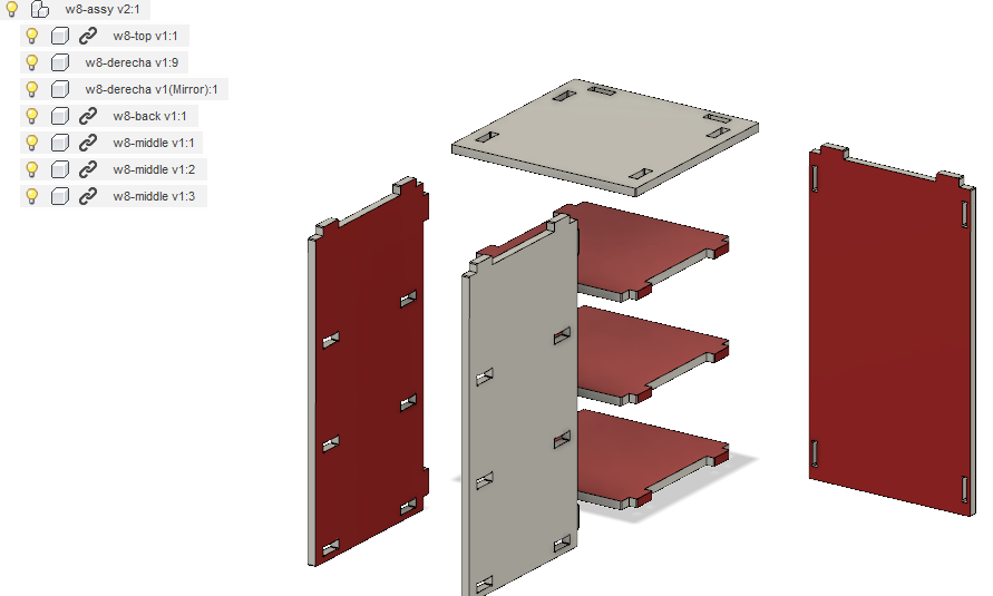
For this week, I'm designing a table for my 3D Printer
I was needing a table with lower slots to keep material cartridge, filament spools and tools. Main dimensions were 400 x 400 mm on top, and aproximatly 650 mm height. The structure
must be rigid enough to reduce normal vibrations during work time, to avoid construction problems.I used a 1/8" tool for this assignment.
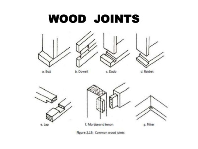
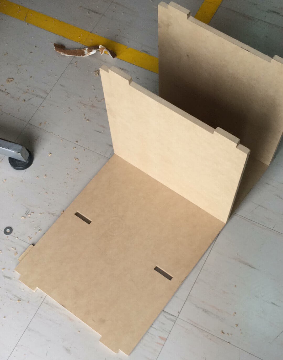
Made a basic box structure with 4 walls and 3 inner platforms to have 3 slots. Files can be found at the end of the page. Used simple pressure joints for assembly (check wood joints picture).
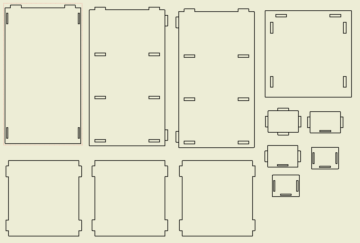
Once all files were designed, made a drawing of each piece. This allows me to export the drawing as a DXF files, to later send it to the Shopbot program.
Comments
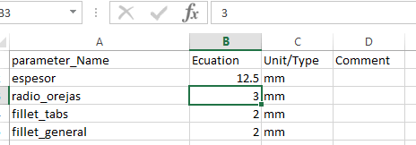
I used Inventor for the design. I made a simple model, but keep it parametric because I didnt know which material thickness we have available at the lab.
Finally used 12.5 mm MDF material.
Originally, I made relief ears on each slot, but was noticed the machine software takes care of that, so removed.
Update
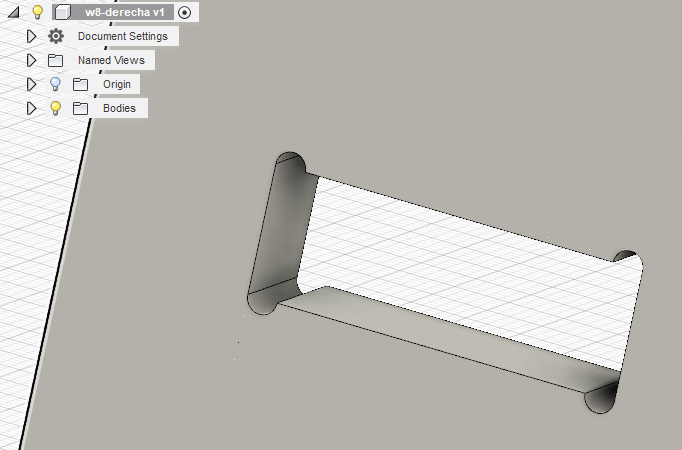
I moved my Inventor files to Fusion 360 to better see how CAD design was.
Machine settings
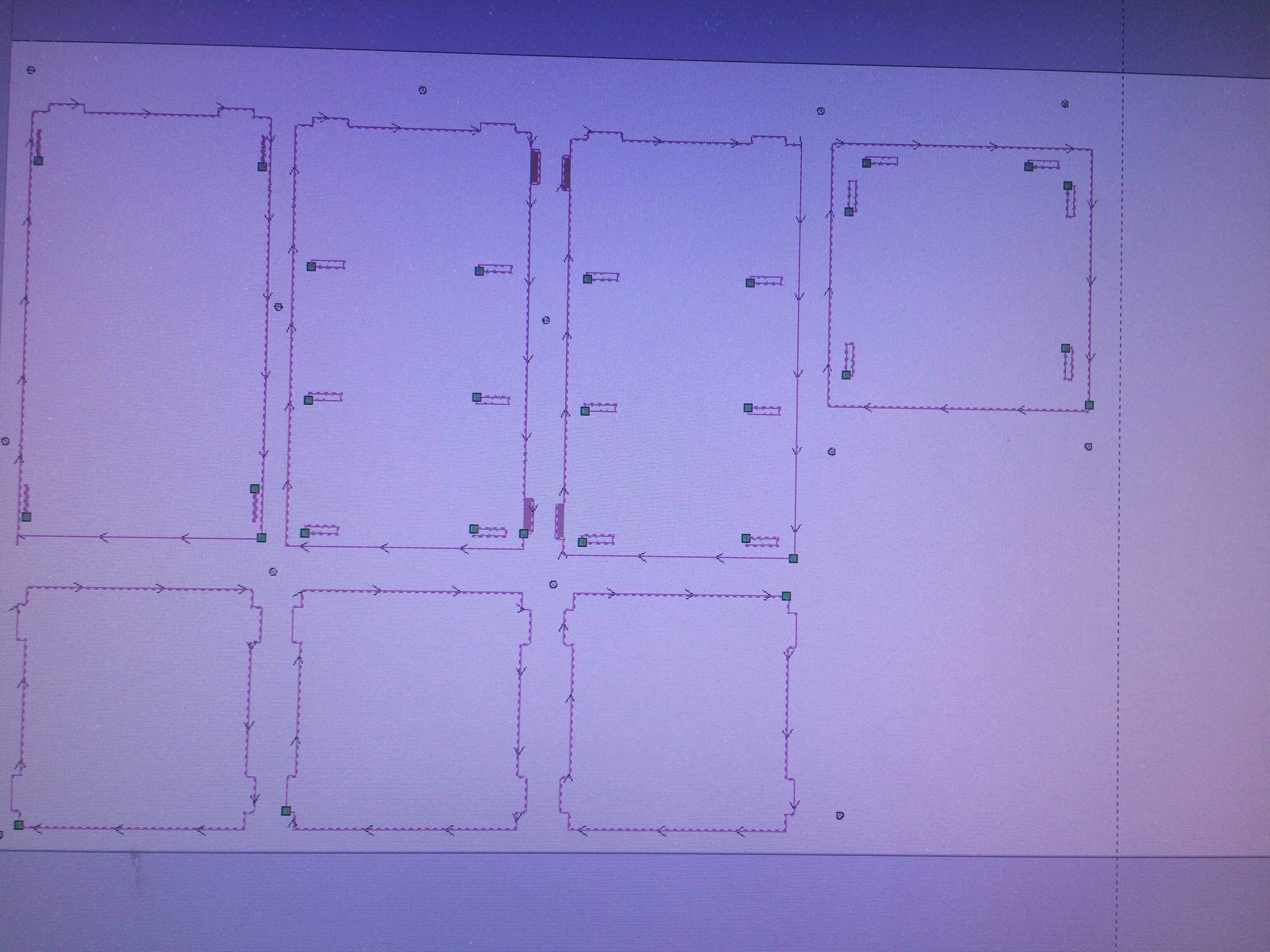
Loaded my DXF file to the Shopbot software Partworks. Create a new file from "Create a new file" option.
First we need to add all pieces to the working area. This is donde with the "Align Objects". Once all pieces are placed correctly (nested),
we need to create the toolpath for the Shopbot. This is donde with "2D Profile Toolpath" button. There we will have to set up the parameters:
Cutting Depths: We are using a 12.5 mm and want to get throught it, so select a passing distance (check parameters next).
Tool Selection: We are needing a End mill tool.
Machine Vectors: Since we are cutting material to obtain the part we want, select Outside/Right.
Next step take us to a simulation of our work. If seems nice, we go to setting machine.
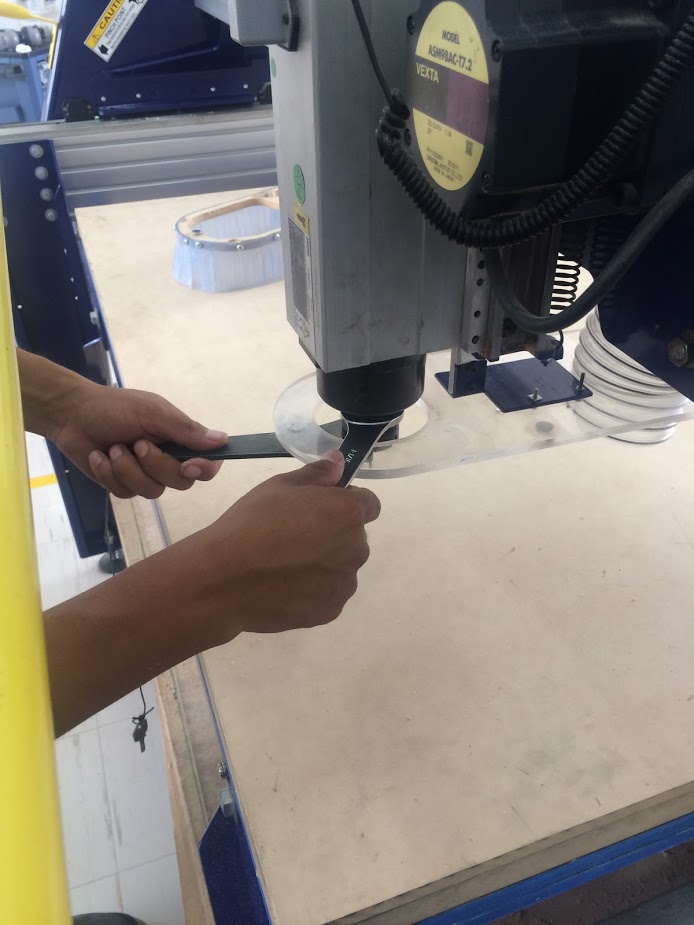
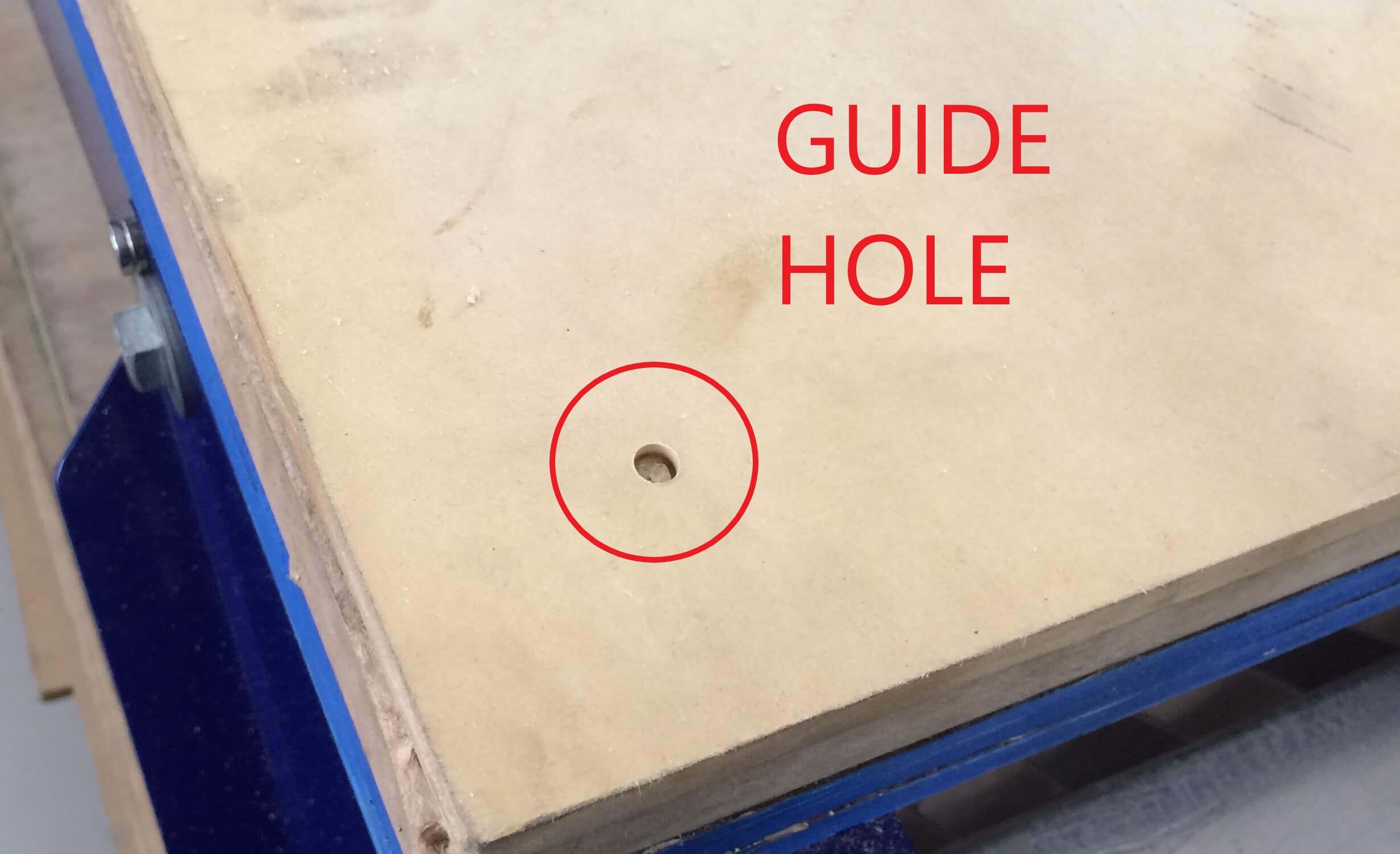
When the program is already selected, we have to prepare the machine. The first thing is secure MDF to machine worktable. I'm using wood screws scattered through the table.
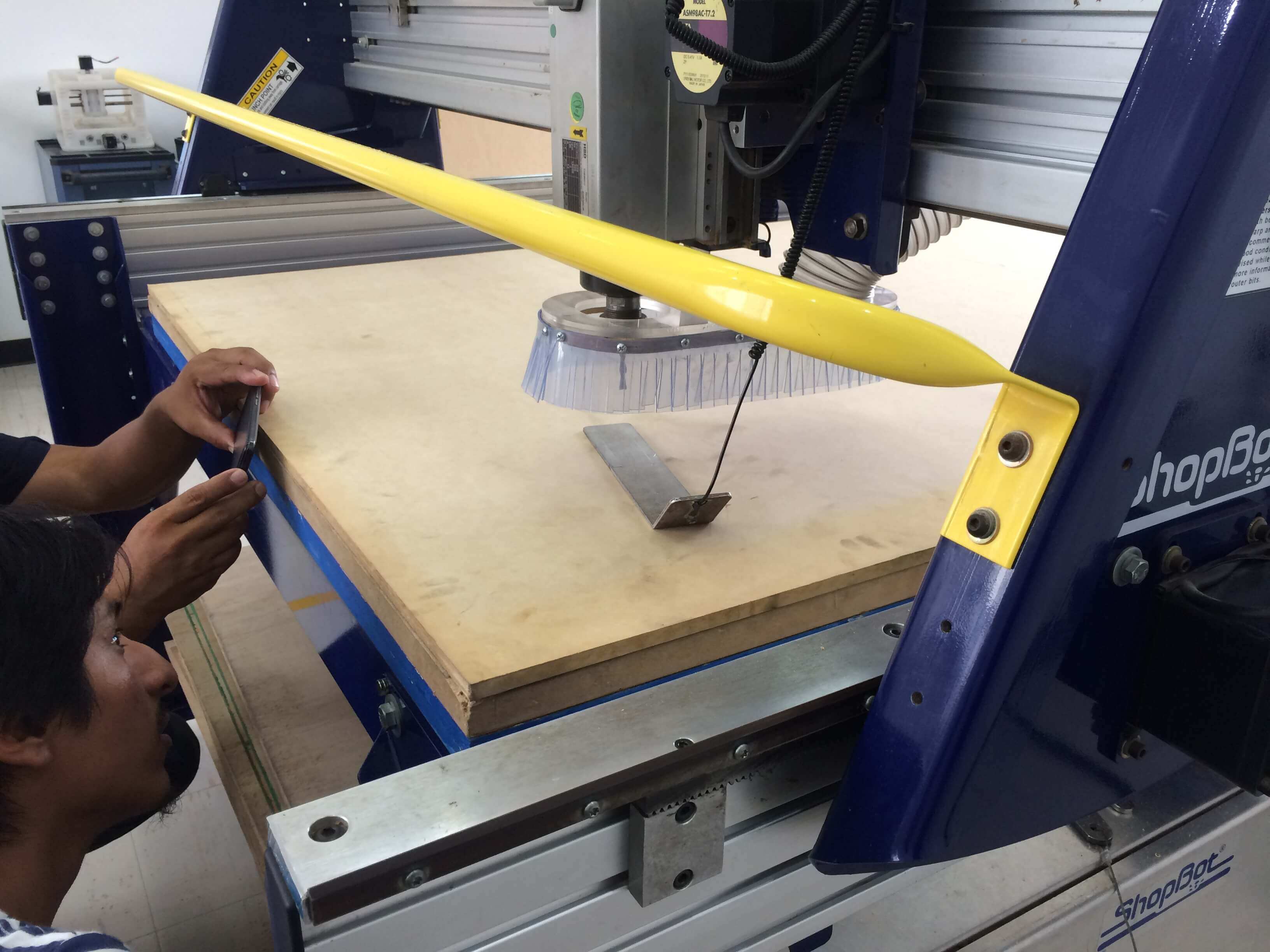
Second, change the tool to the selected one. For this job I'm using a 1/8" end mill tool. Using a metal sheet, we test the tool was attached to the machine at the right height.
Finally, send the program and the Shopbot will start its task.
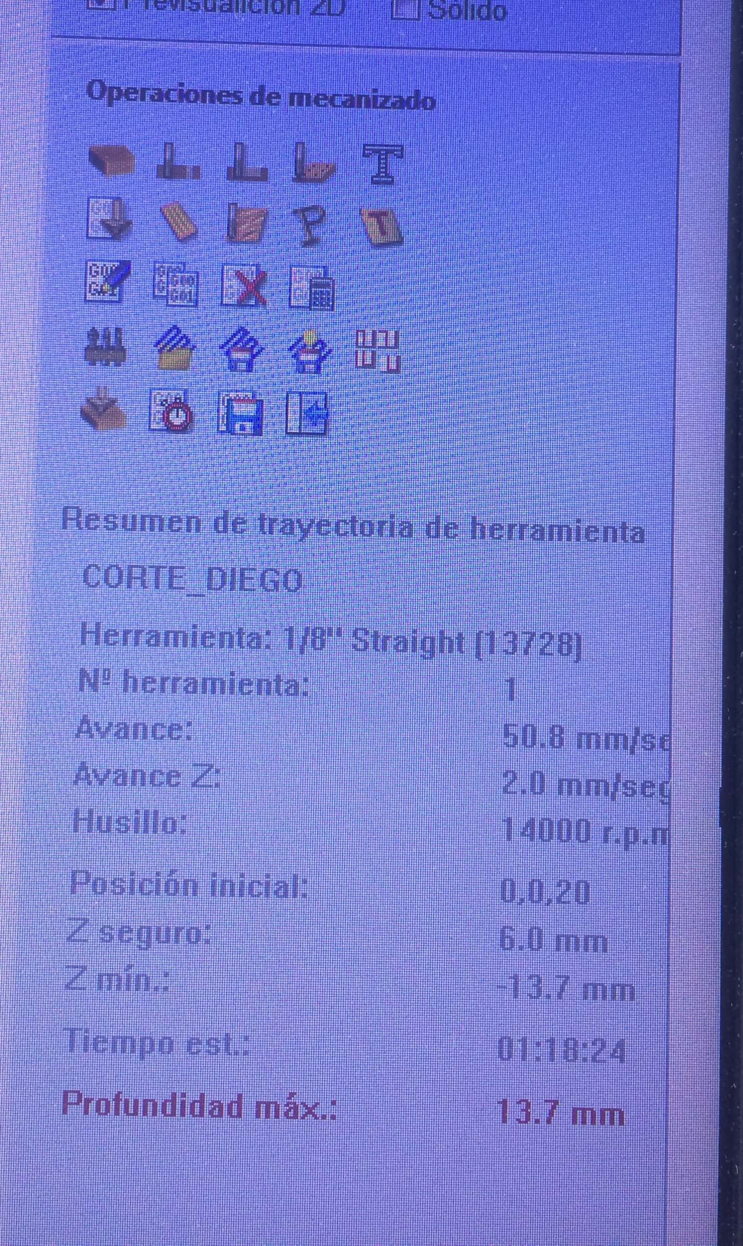
Parameters Summary
Tool: 1/8" Straight
Speed: 50.8mm/sec
Speed Z: 2.00mm/sec
Spindle: 14000 rpm
Initial Pos: 0,0,20
Z safe: 6.0mm
Z min.: -13.7mm
ETA: 01:18:24
Max depth: 13.7mm
Comments
If closing gaps in the vectors is needed, using "Join vectors" will help.
Have some issues with tabs that where half thickness. The software could not process naturally and a sub routine have to be added manually to avoid problems.
As said before, I remove the slot's relief ears to be added in this part, but we forgot to do that.
Milling
My vid for milling
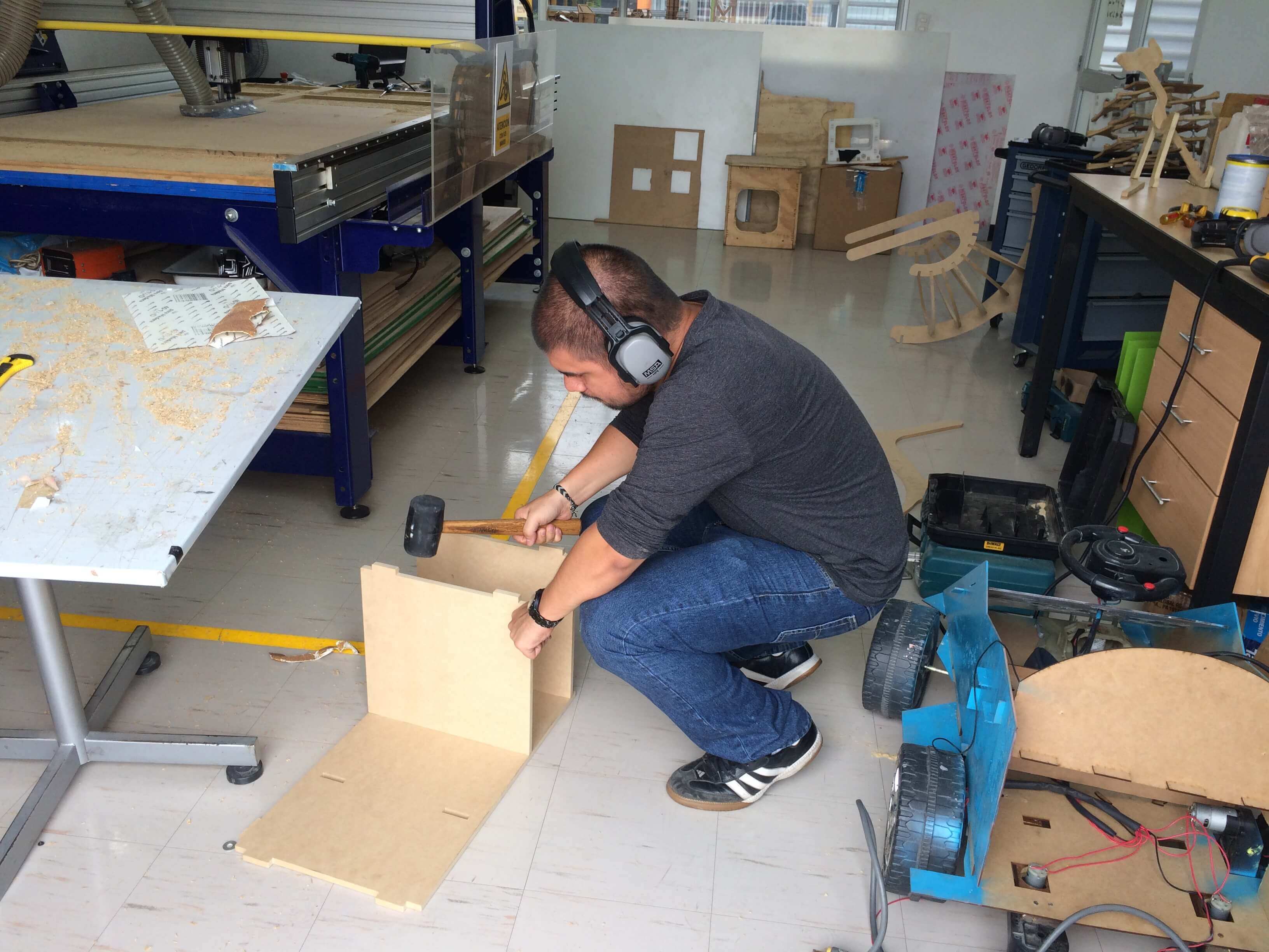
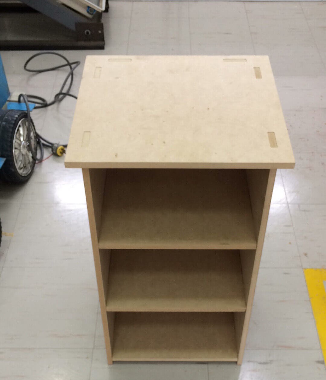
Assembly
Finally the Avengers assembled!
Comments
I thought would have problems without slot reliefs, but in the end it was really smooth