I was thinking to do a electronic game. Something based on Hasbro's Simon, but with a more challenging programmng and a time counter.
Originally I was planning to do the core Simon game (after all lights blinked, you should press each light in the correct order), but with lights switching positions at the end,
but later I found there is a similar Simon game with that features (See Simon Trickster).
Decided to keep sticking to Simon structure, but for my work I will be mixing colors. Using RGB LEDs, mixed colors pretend to confuse players to hit colors wrong.
Lastly, when game starts, a time counter (up to 9 seconds) will countdown each action. If a player haven't press a color and timer reached 0. It will count as wrong hit.
The video shows how HASBRO's Simon Trickster works.
}
I will call my device the FER-1 (Funny Entretaining Recreation - 1)
Planning
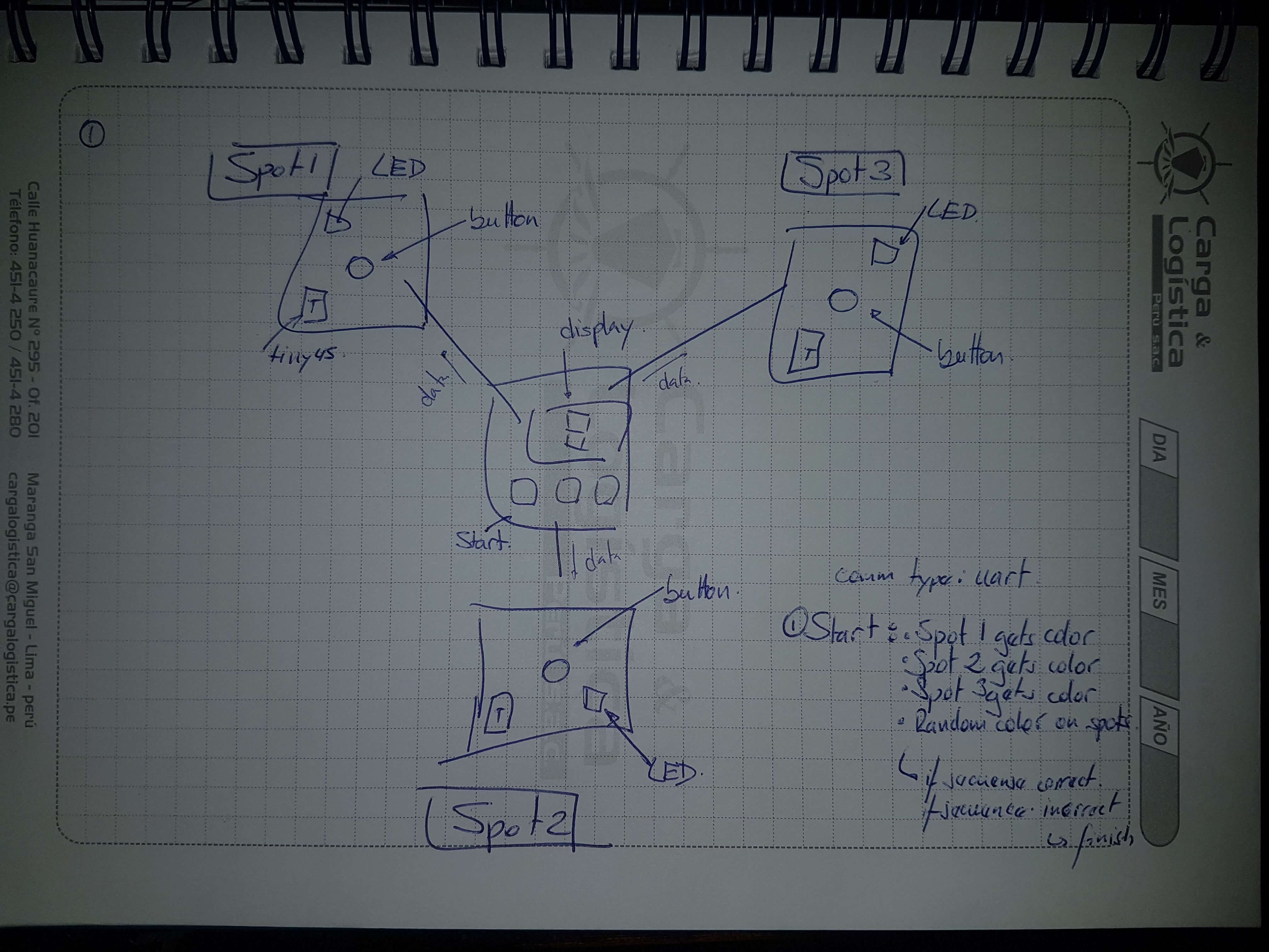
First, my sketch. There it show the Fer-1, with 3 nodes. Each node will have a microcontroller, RGB led, and a button. So when the main board sends the corresponding light,
the RGB will turn on and the button will allow the micro to send a response back.
Each game mode will have the same mechanics:
When start button is pressed, a color will blink (randomly) in any of the possible 3 positions. May blink twice on the same spot or jump to another.
After all secuence has light, randomly a color will display on each spot. All colors displayed are different
The player should press the color accordly to the secuence. If press wrong, the game ends.
If secuence is pressed correctly, the game will blink white color on all spots, which means win.
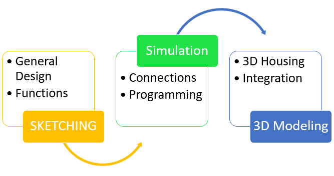
Second, will use TinkerCAD for simulate my system. Using Arduino One and Attiny micro will test connection and programming code.
Third, will develop boards using Autodesk Eagle.
Lastly, will design game housing using Autodesk Fusion. Using Eagle's stp export feature, will use the 3D design of my board and load it to Autodesk Fusion for full mechatronic
integration. Housing will be MDF and acrylic, modelled with Laser cutter.
Sketching
This image shows the first idea of the game. The main board will be a Fabduino, connected to a board which will serve as a hub for serial communication with peripheral boards
(or Spots) and where start button and the 7 segment display will be connected.
The peripheral boards or SPOTs will be small boards with a microcontroller (the first idea was using attiny45 microcontroller), RGB LED and a button.
Using this model I'll use TInkerCAD to run simulation.
Simulation
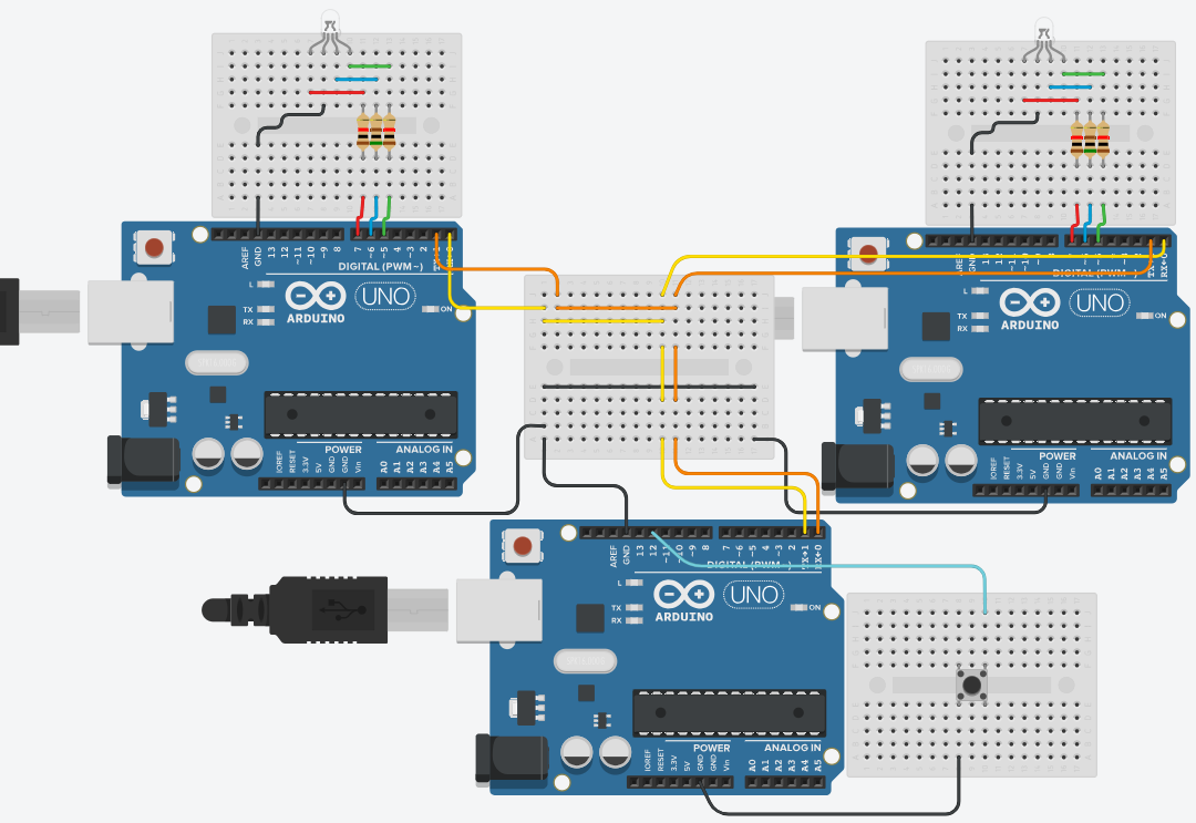
In this part I will test a 2 "colors" circuit. I'm building the circuit using 3 Arduino One (not using attiny yet since im not sure about how many pins do I need).
Created a new schematic in TinkerCAD and loaded:
Arduino Uno x 3
Breadboard mini x4
Resistor x6
RGB LED x2
Button
Simulation 1
One Arduino will act as a command board, the other two will manage actions on each "spot". Final connection shown on image.
With this configuration, my first test: when button is press, the main board will pulse '1', and '2' after 2 seconds. the RGB LEDs will turn on changing between
red, green and purple when character sent matches its ID (ID = 1 to spot 1 and 2 for the other). Code used in this test: main,
spots.
Simulation 2
Now we are making the program much similar to the inteded functionality.