Planification process
At the beginnings, we plan to build a XY positioning mechanism with two stepper motors (one for each axis). This mechanism would move another mechanism with a third motor . This third motor pushes a pin at the time. Once all the pins are in position, and the LED lights are turned on, the return to the initial position is throught a reset button. This button makes the pin returns to the initial position, due to a elastic band inside it.
Mechanical components
The machine is divided on three main parts. Each part is an independent mechanism actually. these parts are: Pin mechanism, XY positioning mechanism and Pushing mechanism.
Pin mechanism
The most critical requirements for this mechanism are the quick return and holding position. We have only a push motion to reach the position of the pin. This pin needs to hold this position by itself. By other hand, we need to return the pin to the start position as faster as posible. Due this we think the reset of the position needs an unique action for all the pins.
This requirements are really a challenge, so we start with some tries. We start with acrylic material and laser cutting. Later, we tried with PVC cable rails without success. Finally, later a long search, and with 14 versions we has a pin mechanism that works really good.
The 14 versions was modeled on Fusion 360 software.

Some versions of the mechanism of pin.

The final version (v14) on exploded view.
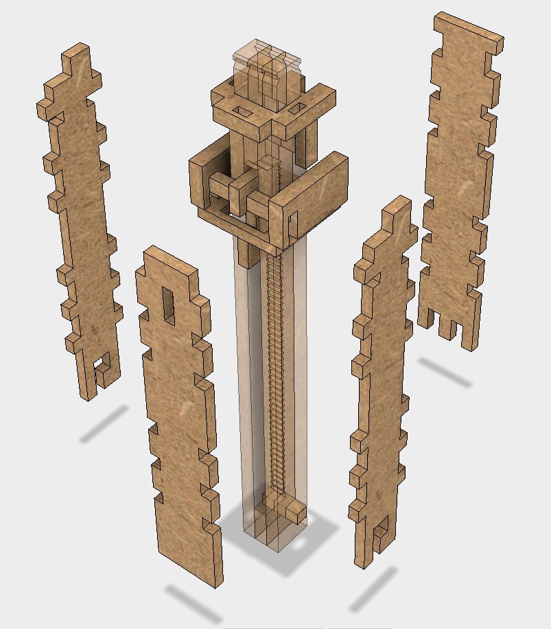
This version is made completelly on MDF an uses a elastic band.


Finally, this video shows how the pin mechanism works.
Push mecanism
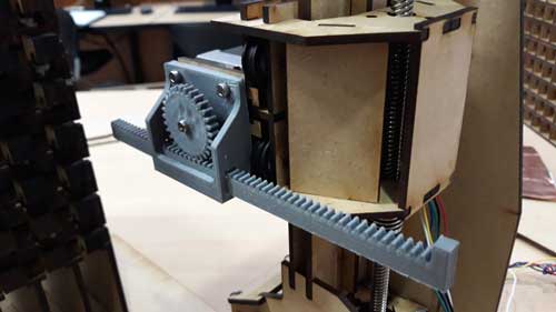
This mechanism is the simplest of the three. It consists of a rack pinion mechanism. The pinion is fixed to a stepper motor. This pinion is in contact with a rack.
We decide to make this with 3d printing process, due to is more simple get a support for this mechanism. The next picture shows the 3d printing process.


the parts 3D printed.

The assembly of the mechanism.
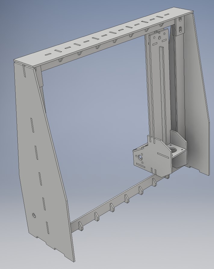
XY axis
To reach all the pins and position it, we design a mechanism made completely on MDF. This material is versatile but need care to obtain the stiffness needed to the movements. With this in mind, all the joints (or the most of them) has at least 3 faces, to guarantee the pieces are joined.
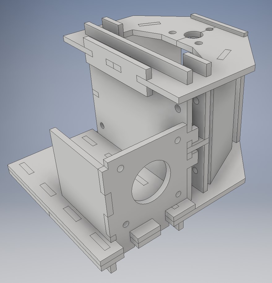
This is the rail and support of the third stepper motor. All this pieces are modeled on Autodesk Inventor.

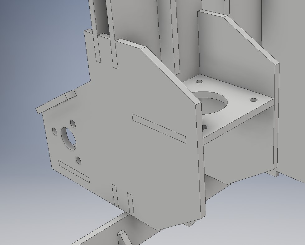
This is the support of the Y axis stepper motor.
This is the frame for the X and Y axis.
Assembly of the machine
Before the physical assembly, we build the 3D model of the machine on Autodesk Inventor, to prevent any clash during the assembly.
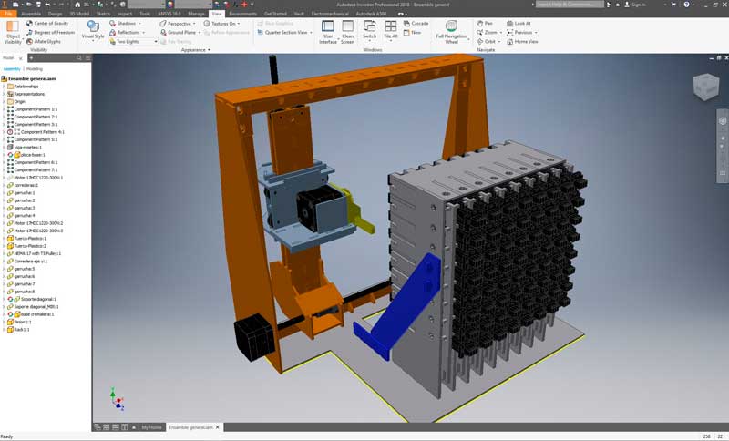
Push mechanism assembled.

General assembly (of mechanical components) completed.

Later the design stage, we generate the dxf files for laser cutting, then cut the MDF and starts with the assembly.

These are rollers used on windows. Are good enough for this purpose but are not accurate if you want to build a cnc.

These are parts of the third motor rail and support.

The assembly process of this support.

Then, we mount the stepper motors for the X axis.

Now the Y axis.

Finally, a milestone reached. The assembly of the mechanical components take us a lot of time but the result was really nice.
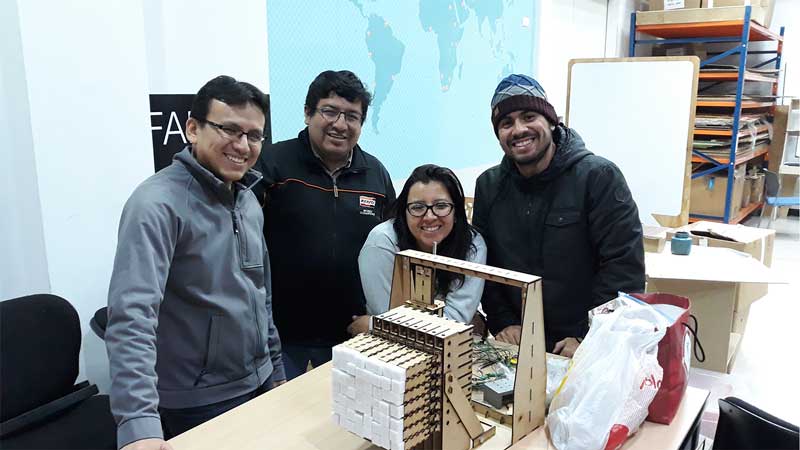
Was a good team work.
The dxf files for laser cutting can be downloaded here.