8. Computer Controlled Machining
The requirement for this week's assignment was to 'make something big', and so I decided to create a table. I looked at different techniques for assembling my final project, and separately, the table.
Slicer Plug-in
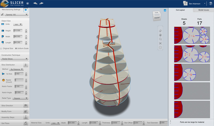
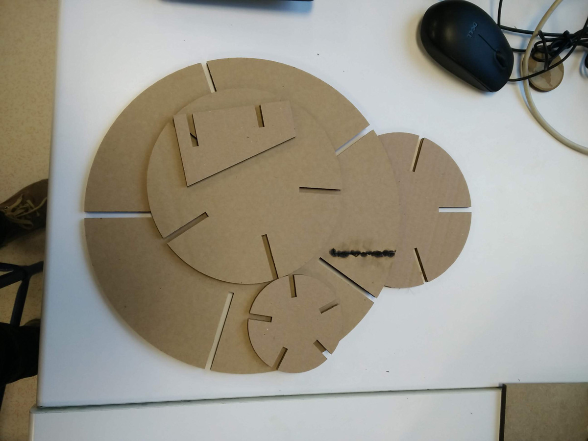
I attempted recreate the buoy using a sliced system and press-fit construction. To do this I worked with Fusion 360 Slicer plug-in, laying the slices out onto as small an amount of sheets as possible.
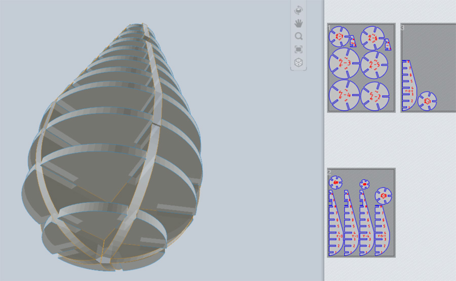
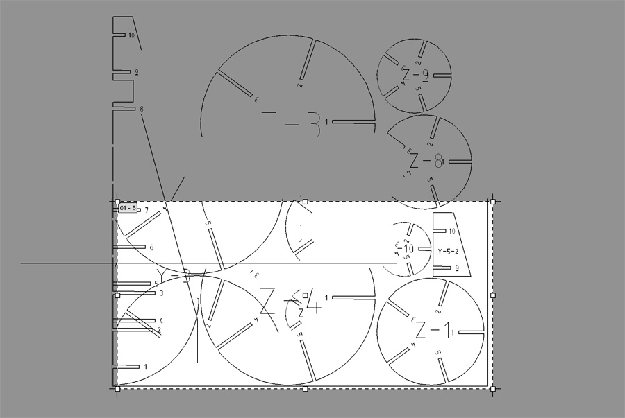
With the plug-in, you have a great amount of control – it is even possible to vary the angle of the cuts and construction technique. I chose 'radial slices' as this produced a round curve at the base. On export, there were some challenges setting up the artwork for cutting. I tried exporting as a pdf, eps and dxf but each time the artwork fell short of the artboard and had to be repositioned in Inkscape.
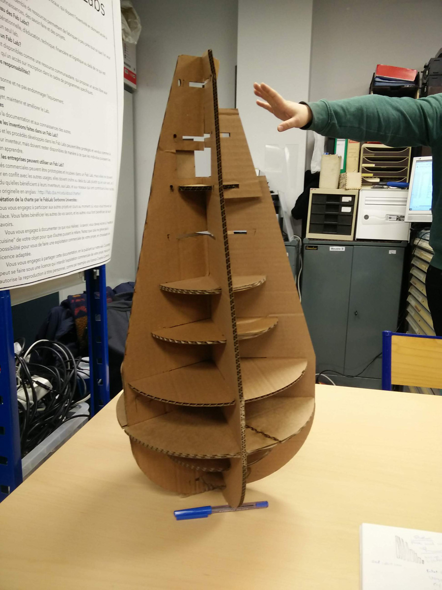
I worked with cardboard and the lasercutter to cut the slices and then had fun assembling. The buoy did stand up, with a little help from a pen at the base. To be fair, it was a useful prototype to consider how I might construct my final prototype and also to think about its proportions. It's clear that the final (plastic) buoy will have be thinner, so as to be less stable and more likely to be knocked over. The height was looked good, but there was no benefit in creating a giagantic buoy. What became clear was the buoy was not going to fulfill this weeks brief, to make something big.
Mermaids & Sailors
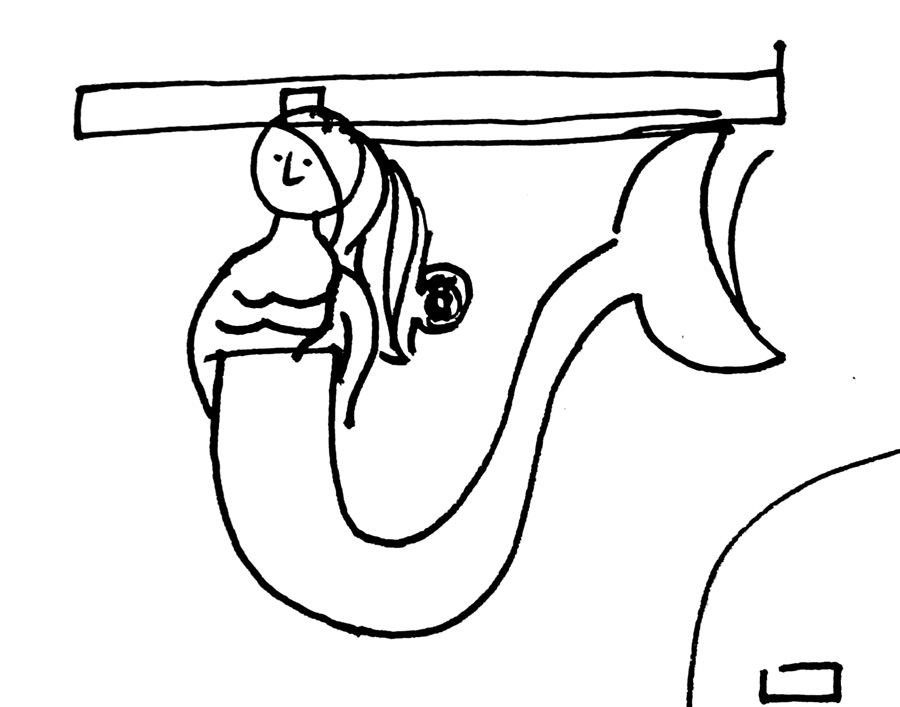
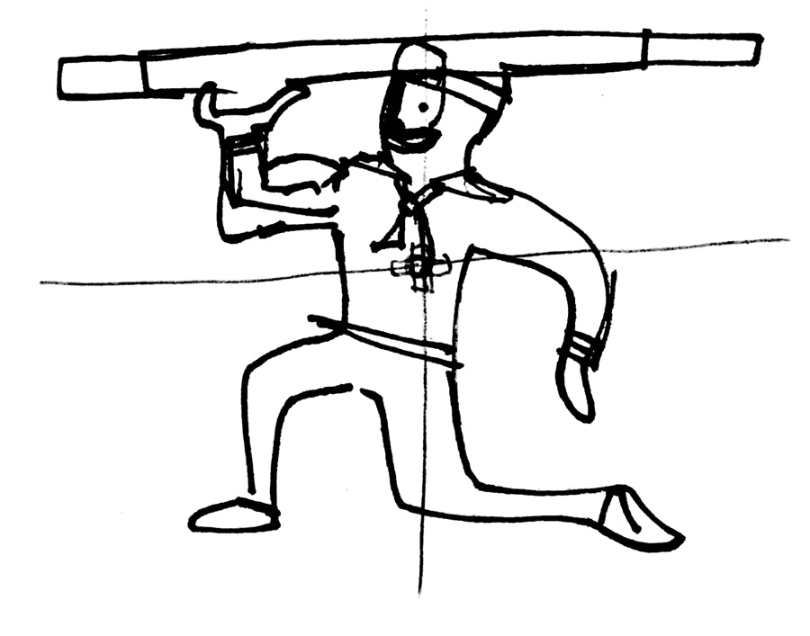
I started work on a madcap idea I had for a 'high seas' table. The idea was there would be a mermaid and sailor at the base, supporting the weigh of the table top. Figurative sculpture on water features (eg. water fountains) is common in ancient Greece and Roman architecture. I was hoping to work on detailed characters, and also to add a nautical theme to the table top (charts, landscapes).
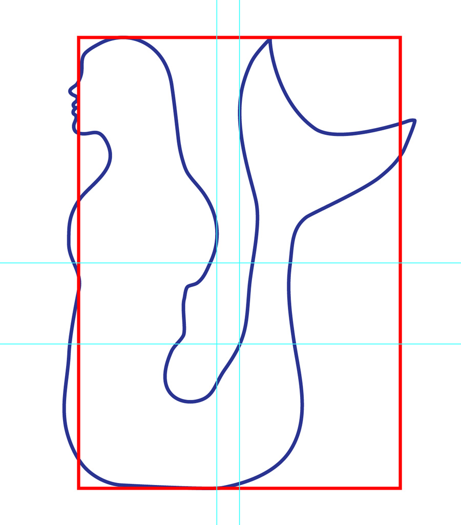
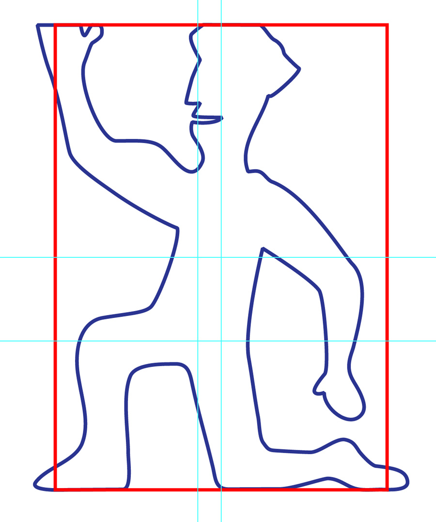
I drew the two characters around a 500x700mm rectangle, the proposed dimensions of my table base. I changed the body position to suit a flat base that would support a table. I worked quickly to cut the drawings on the lasercutter with 3mm MDF. Because both the material was thin and the joints at the top of each character were short, it was difficult to stand the prototype upright.
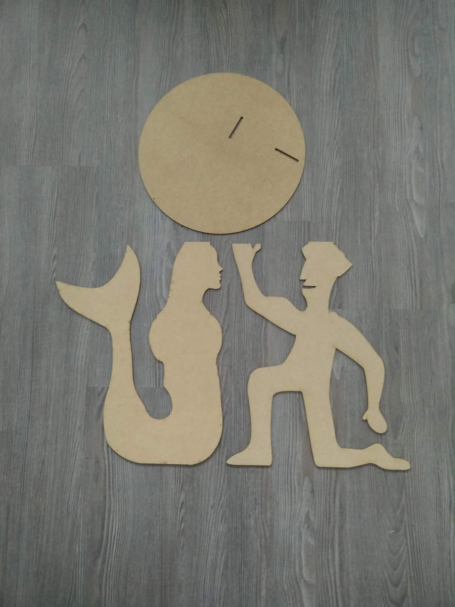
The direction for the sailor proved too cartoonish for my liking. Faced with limited time (and a broken Wacom pen) I decided to duplicate the mermaid character – Because her facial features are more vague, it appeared better suited to a piece of furniture. This challenge, cartoon vs realism is summed up well in this tweet.
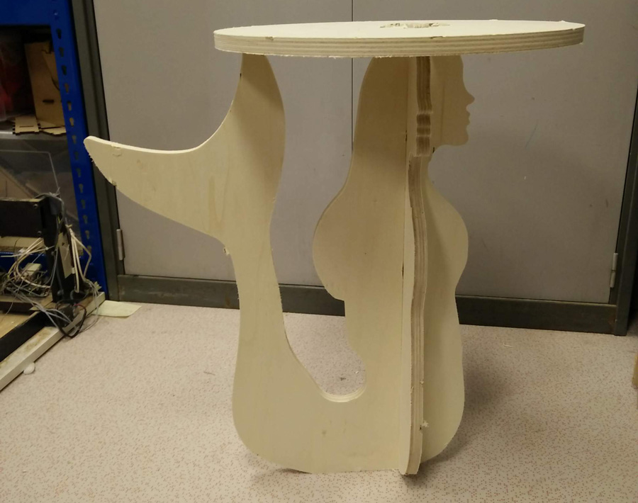
A Prototype Table
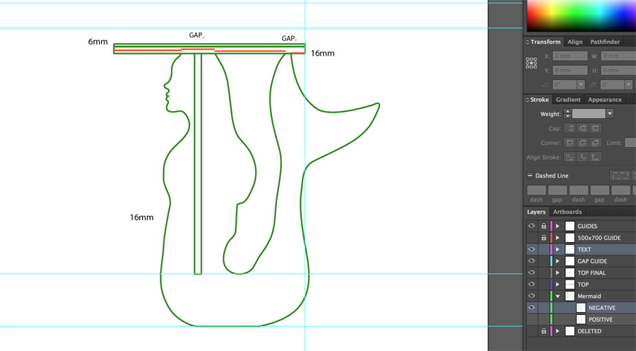
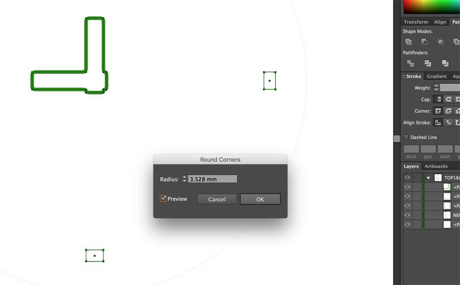
One of the challenges with the design was positioning the mermaid in both axis. I didn't want the table top in a central position, but rather have the tail exposed on one side. This proved challenging to complete in Illustrator as I had to imagine the two-axis in 3D and work out the position for the slot (head) and pocket (tail) mathematically. When I was happy with the position, I used Illustrator's round edge tool (under Effect > Stylise) to match approximately half the diameter of the tool (3.528mm). In hindsight, this should probably have been reduced.
I discuss the testing of the Shopbot CNC on the Sorbonne Group page.
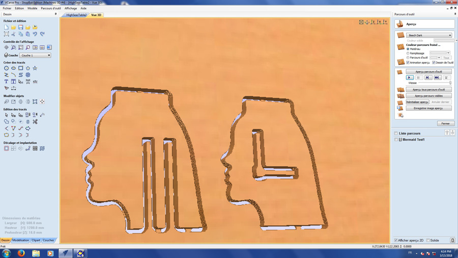
In VCarve Pro software, I first prepared a text file with the mermaid's head to see how the slots would it on 18mm. On one head were two options for slot thickness: 18.25mm and 18.5mm. I used tabs on all cuts except the one due for the tabletop – I would use tabs for this in the final piece.
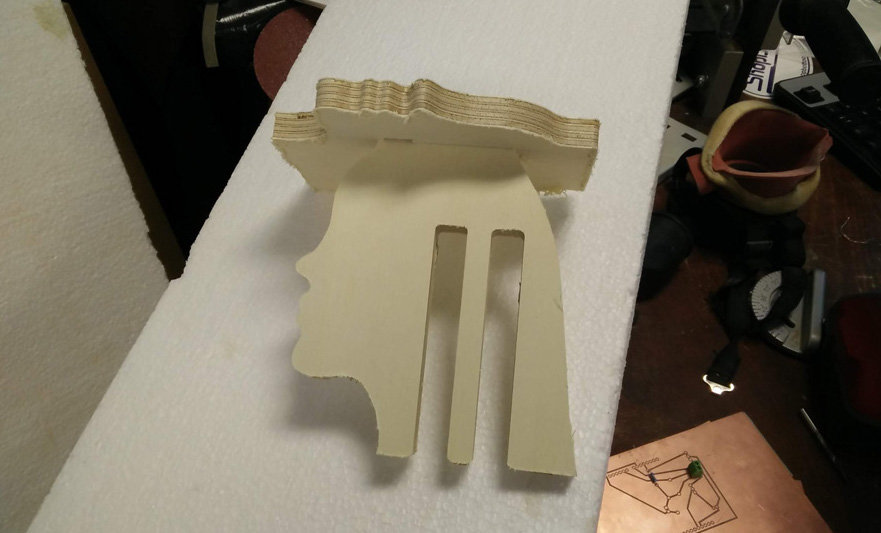
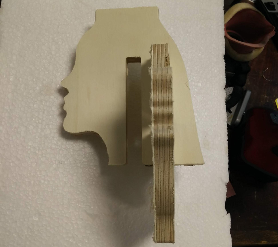
The slots with a gap of 18.5mm fit perfectly.
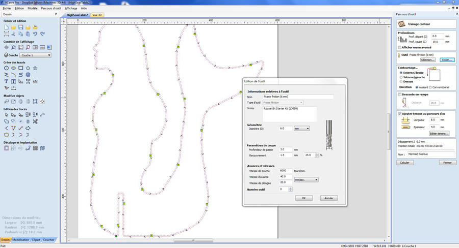
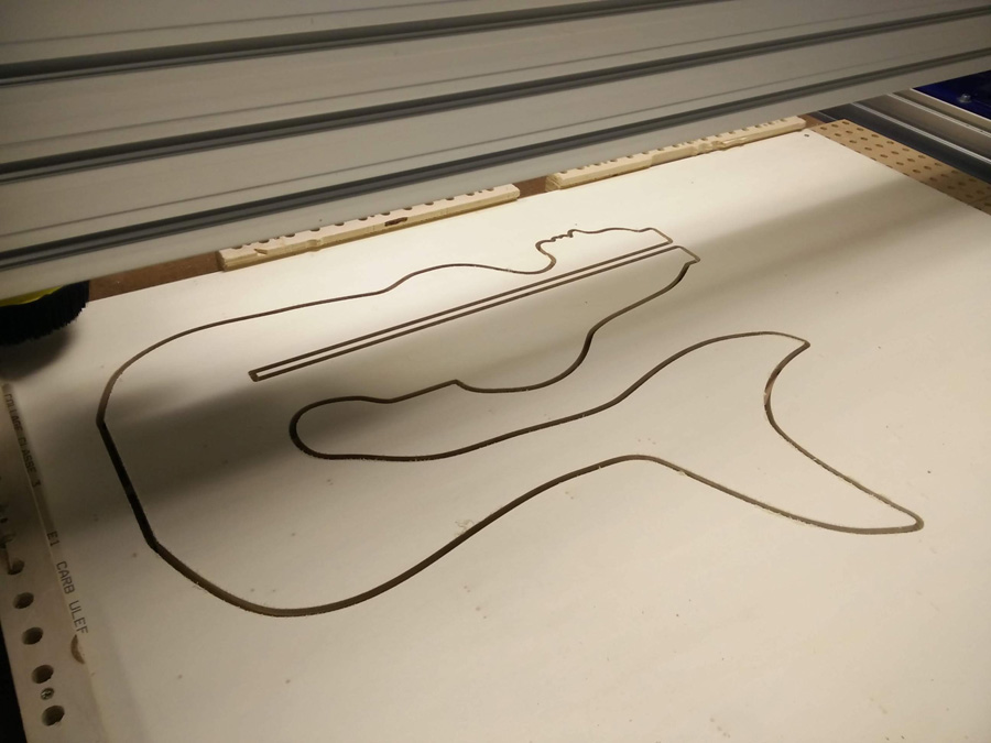
In the same file as the test heads, I prepared the cutting path for the table base (mermaid positive and negative). On the positive, I plunged to a depth of 19mm using a 6mm tool. This was the first error: Not staggering the plunge into smaller steps.
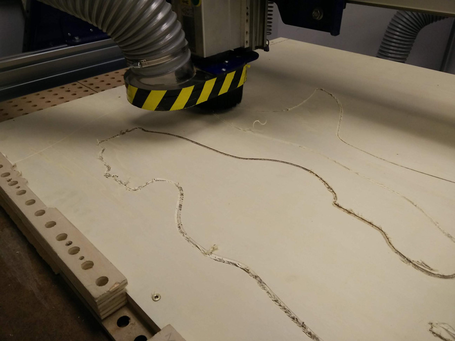
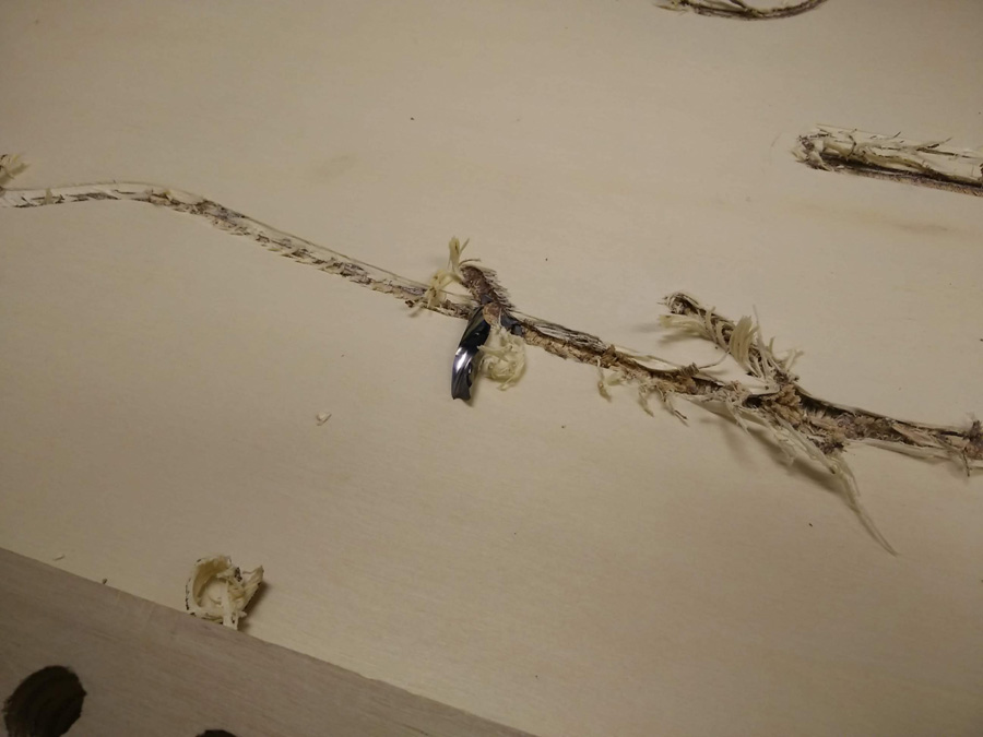
The result was quite a poor cut. I paused the job and I reviewed the file together with Adel. After changing to a newer toolbit, I ran the job for a second time. This time I broke the tool bit! I had forgot to re-engage the CNC after changing the tool-bit. Lesson learned.
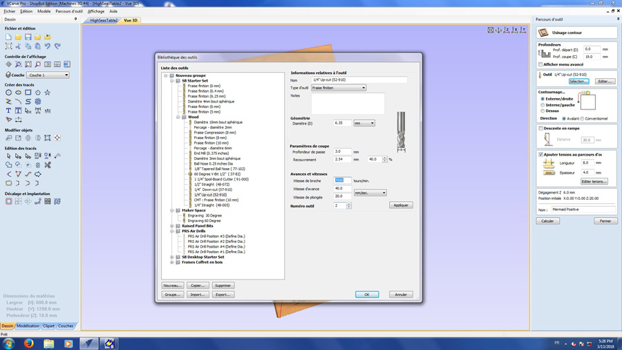
The next time I cut with the CNC I used different settings:
- 1/4” Upcut
- 3mm depth of pass
- 2.54 mm recovery @ 40%
- spindle speed 7000 tours/min
- advance speed 40
- 2.54 mm recovery @ 40%
- plunge speed 20
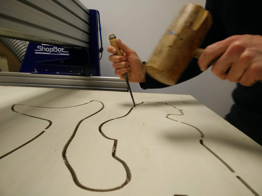
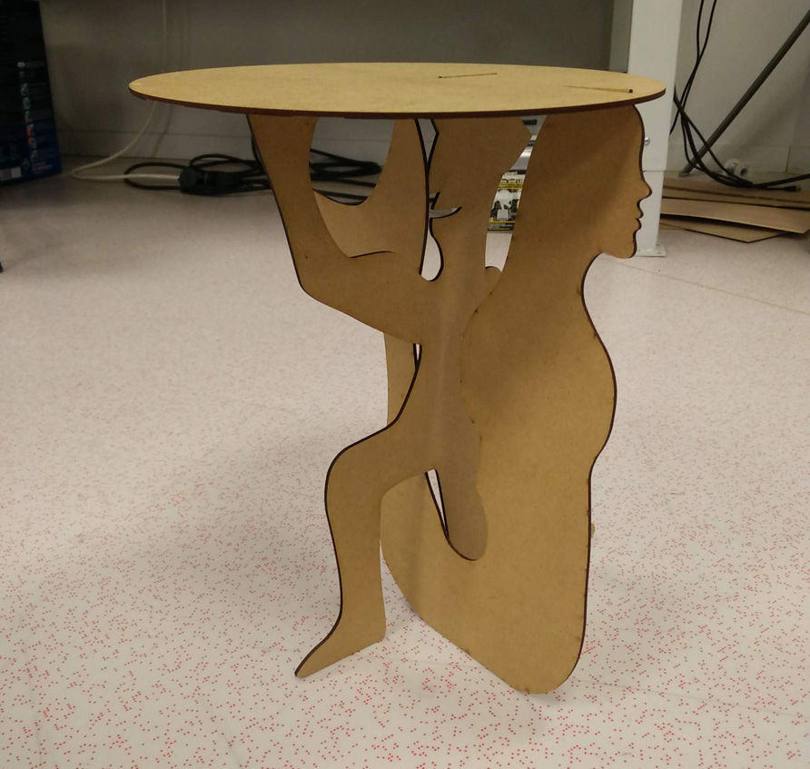
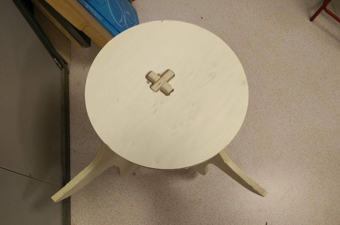
I was abled to create a smooth cut and used a mallet and chisel to remove the tabs from remaining wood. The negative mermaid fit snugly into the positive. The pockets for the fin matches perfectly but the slots for the table top were slighlty too wide – based on the round edges error. In hindsight, it would have been better to create a pocket on the reverse side of a thicker piece of wood, but weighting bearing may have been an issue.
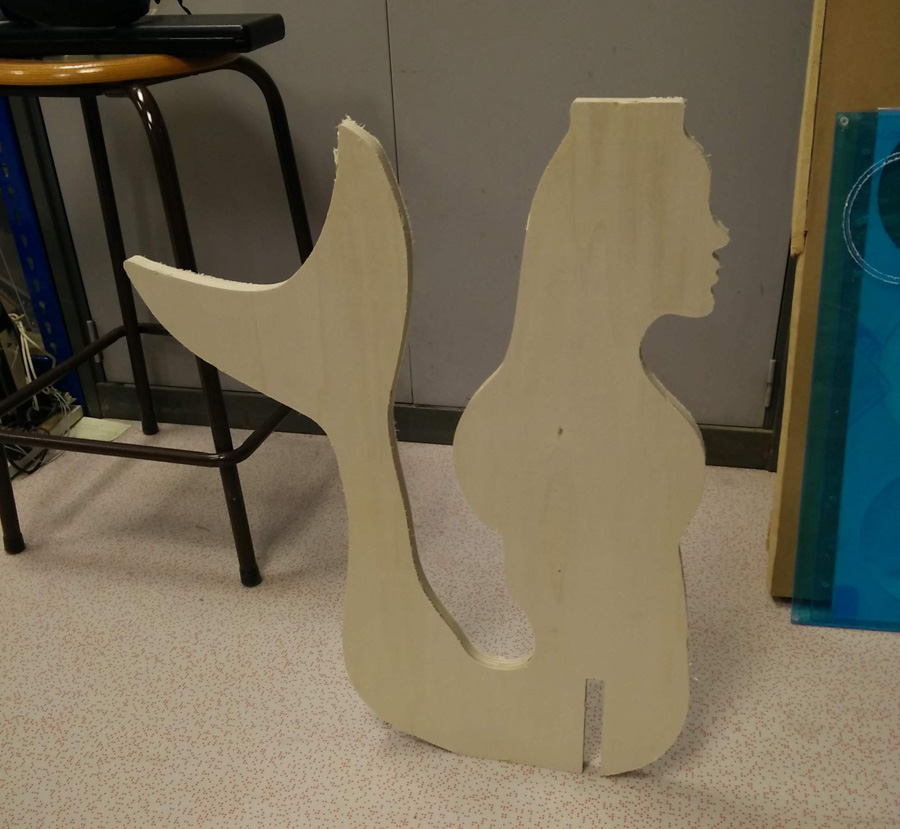
The fins stand out at a slightly hazardous length. For a future prototype, I am considering using the top of the fins as a tray area. It was also suggested that the shape could be used to assemble a connected seat.
Back to the top