21. Final Project Requirements
This week I integrated my electronics and mold into the 3D printed parts, testing appropriate counter weight.
Presentation Slide
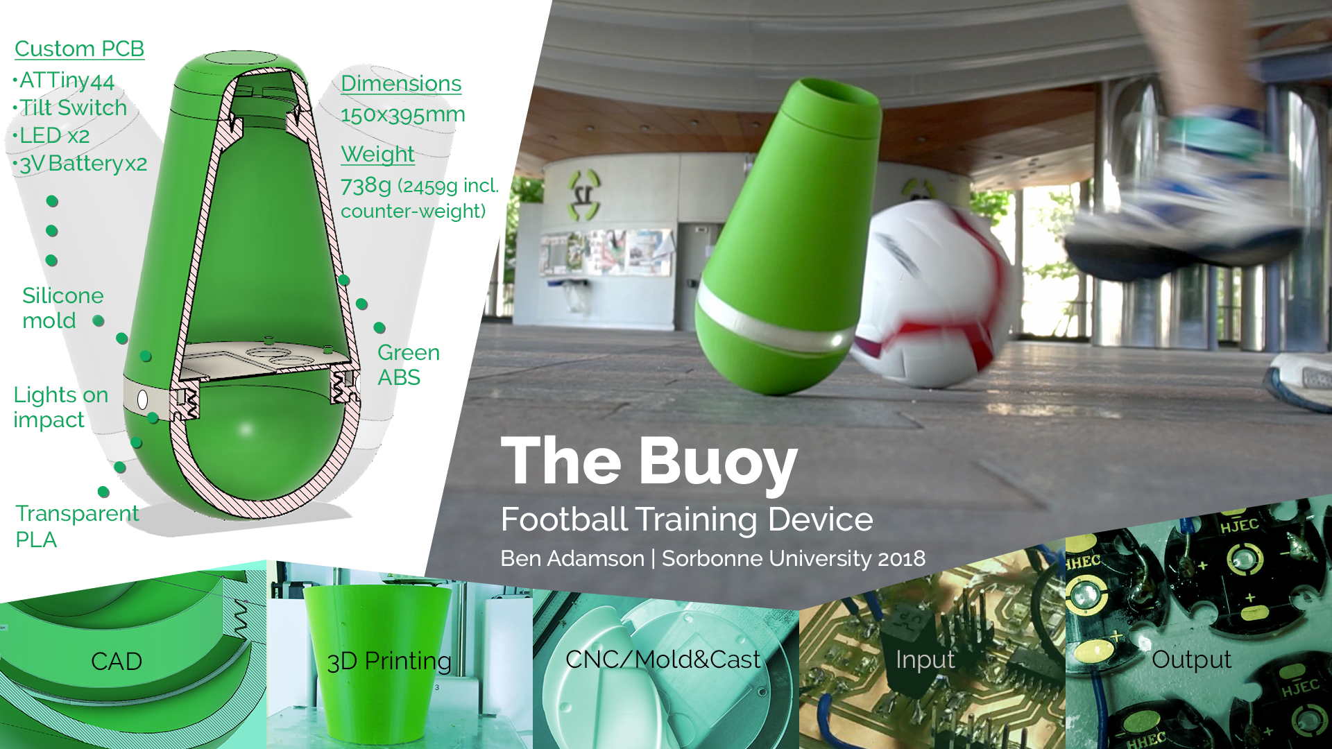
The first task this week was to create a slide summarising the final project. I chose to divide my slide into different sections conveying the process and provide a summary of the materials, dimensions and weight. Note: You can click on the slide to enlarge.
BOM
BOM as downloadable image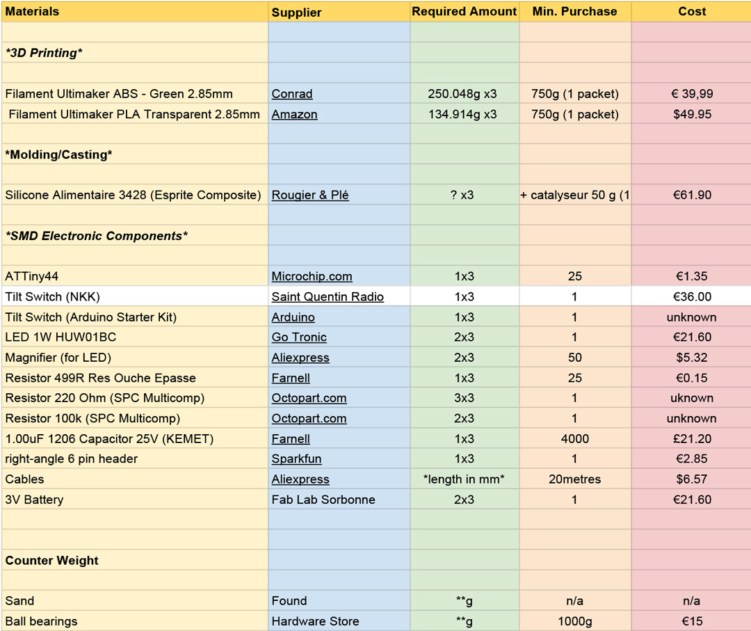
Integration
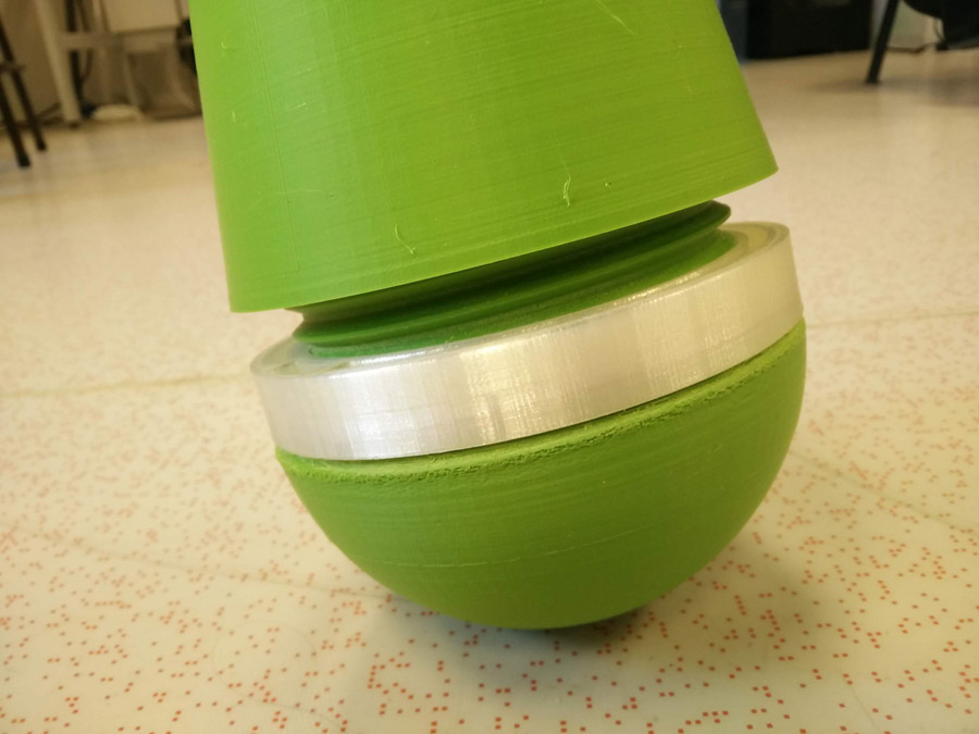
I started by attaching the light thread to the base. My press-fit construction was tight, perhaps as ABS is more likely to deform during printing than PLA. I did quite a bit of sanding to get it to fit. I also attached the top to the mid section.
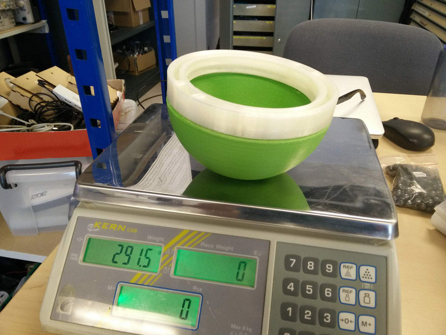
I measured the weight of parts as a guide for my counter weight. The top, mid, electronics and mold combined were 527.5g. The base and light thread were 291.5g. I use 291 grams as a basis for doubling the weight of ball bearings.
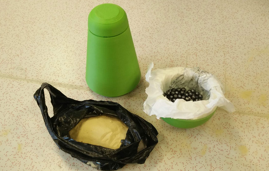
I gathered sand and ballbearing into plastic bags which were cut to shape.
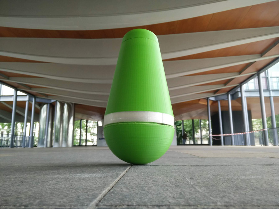
The right balance was a challenge: I tested the buoy by pushing it over in different directions, seeing if it right itself. When it didn't I added a combination of more ballbearings and sand. To achieve the desired effect - , I had 4x291g (1,164g) of ball bearings and 548g of sand, a total counter weight of 1,712grams.
I then tested the position of the mold within the mid section, as in the video above.
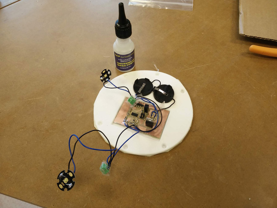
Time to fit the electronics. I used superglue to stick the pcb and battery holders to the mold. The LEDs had been fit with small junction box so that I could fit the wire after the thread was locked. But this wasn't required because I had left an opening on the rim of the base (image below).


Between test, I removed the coin batteries from the two holders.
A test with the buoy in bright conditions: The light is not very visible.
A test with the buoy in dark conditions: The blink is visible when the buoy is knocked over.I made a final edit to the program using the Arduino IDE. I left the LED on for a longer period (delay: 3000). With this final edit, I tested the buoy under 'football' conditions.
One Buoy (for now)
I had proposed three duplicates of a prototype, to be used in the triangle game. It took me the full six months to learn the skills to 3D print, CNC, mold, cast, cut and program it. The remaining three weeks were only enough time to create one finished prototype.
Evaluation
Because there was only one buoy, the triangle game had to be varied: Two players passed as close to the buoy as possible witout hitting it.
On light impact, the prototype worked well - Righting itself after moving and lighting the two LEDs. With strong impact, however, the base separated from the lighting thread section. I would therefore make the following improvements with a second version,
- Further explore rotational molding: Lighter material would require less counter weight and therefore a much lighter buoy.
- Combined dual-extrusion for light thread and base. This was the system used during tests: Because of a blocked extruder, I had to press-fit between the two parts. Combined dual-extrusion would remove any risk of the parts separating.
- Cast the counter-weight: This would ensure no internal movement of the sand and ball-bearings, giving better stability for righting itself.
- Lighting upgrade: I would return to the idea of using a 12V LED strip, illuminating the full circumference of the buoy. This would involve editing the board design and possibly adding a second regulator (For 12V to 6V).
Video
The final step was to create a video (top of page) summarising the project. This was edited in Adobe Premiere.