Molding & Casting
this week assignement are:
- Explained how you designed your 3D mould and created your rough and finish toolpaths for machining
- Shown how you made your mould and cast the parts
- Described problems and how you fixed them
- Included your design files and ‘hero shot’ photos of the mould and the final object
Design a 3D file for molding what to keep in mind.
for this week project i decided to make a simple Pyramidal mold where i will implant some led on my final project. the idea is to tell people when a record is on.
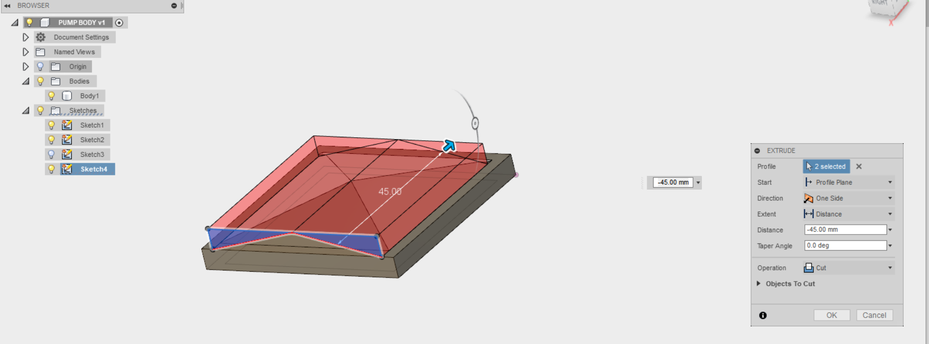
making it in fusion was pretty simple.
 When we are making a mold we have to keep in mind at least two things:
Clearance and retractation:
Clearance:
when you will try to unmold your silicone from the wax if you don't have any clearance with at least 0,5 degres.it would be hard to unmold, and it could broke during this step.
Retractation:
When you are making a mold you have to know what will be the last final material you will use, if you think using some epoxy, no worries,it will work like a charm and you will have all the dimension you made on your CAD project.
but if you thinking to make some stuff in ceramic. it count.
With some material, the retractation could be at 8 or 10% of the first cut. so you have to make your CAD file bigger.
the best way to know if your material is good is to check the datasheet of the material you are using.
 when my file was ready i export it in STL format Fileand i import it on vcarve PRO.
Vcarve Pro
On Vcarve i imported the STL file .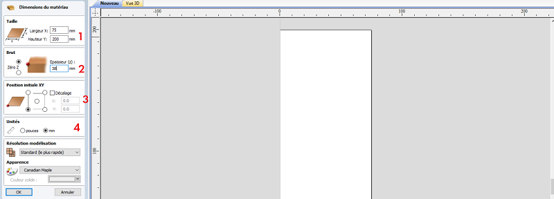 vcarve is made for transform vector file to GCODE, so the first step is importing the file.
- 1) this is the value of your sheet of wax (here in our lab we have some 75 X200mm)
- 2) this is the thikness of your material here my sheet of wood is 38mm
- 3) this is your origin point. always start bottom left, if you want to change that, be sure of what you doing.
- 4) This is the unit, here in paris we using our machine is in millimeter not in inch
Making the roughing path
when you make the roughing path, we should always remove the material as quicky possible and living just an small amount of offset for the finishing path, for doing that with an Stl file with VCARVE PRO V.8 you have to open the specific 3D tab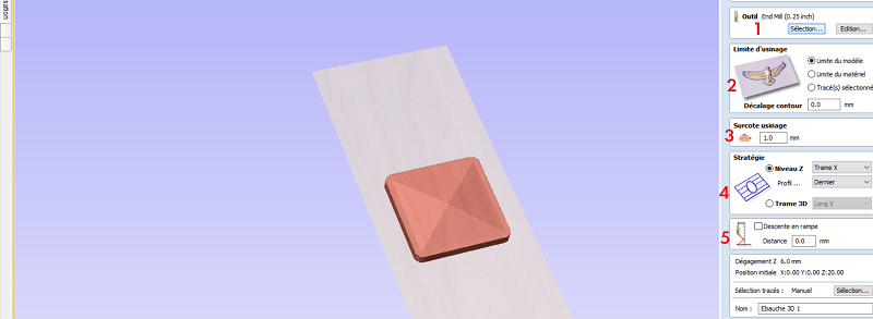
- 1) here you are choosing the good tool.
- 2) this area is made for define the cutting part are you milling juste you piece or all the wax?.
- 3) you have to choose how you want to mill your piece on the X or on the Y axes.
- 4) This is the unit, here in paris we using our machine is in millimeter not in inch
- 5) when you are using a bit, you have to make a ramp inside the material. all the bit are not made for cuting with the end of the bit. so it's good to had a ramp every time into your mill
Making the finishing path
For the finishing part, it's pretty straight forward.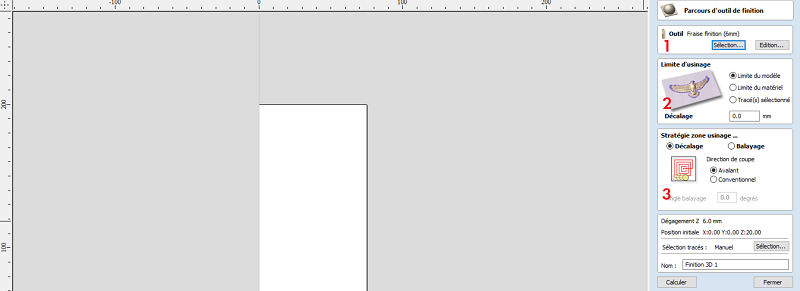
- 1) we are choosing the finishing tool.
- 2) like the roughing part, you define the zone of milling (it's really better to choose se same as the roughing part.)
- 3) for the finishing part you have to choose the way it will mill concentric or from left to right.
open shopbot3
Shopbot3 is the software for controling our cnc. like for Something Big week i used here i'm explaining how to use shopbot3 open it :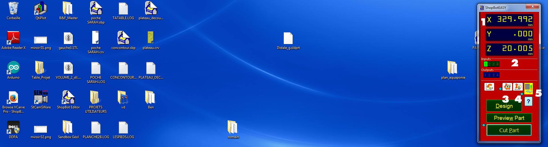
- 1) is the position of the spindle on the cnc
- 2) are the inputs you can have on your cnc (for exemple The 1 light up is for the automatic ZERO Z)
- 3) is an automatic tool for making the absolute zero on X.Y of your machine.
- 4) is an an automatic tool for making the Relative Z zero
- 5 it will open the control box for moving the cnc
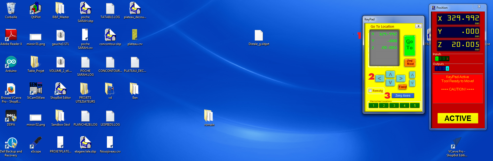 here you have multiple tool.
- 1) is the position of the cnc, you can modify the value and clic on "go to"
- 2) is for moving your tool too, but manually, just click on the arrow and it will move
- 3) Zero axes, is made for making a relative Zero for starting your file
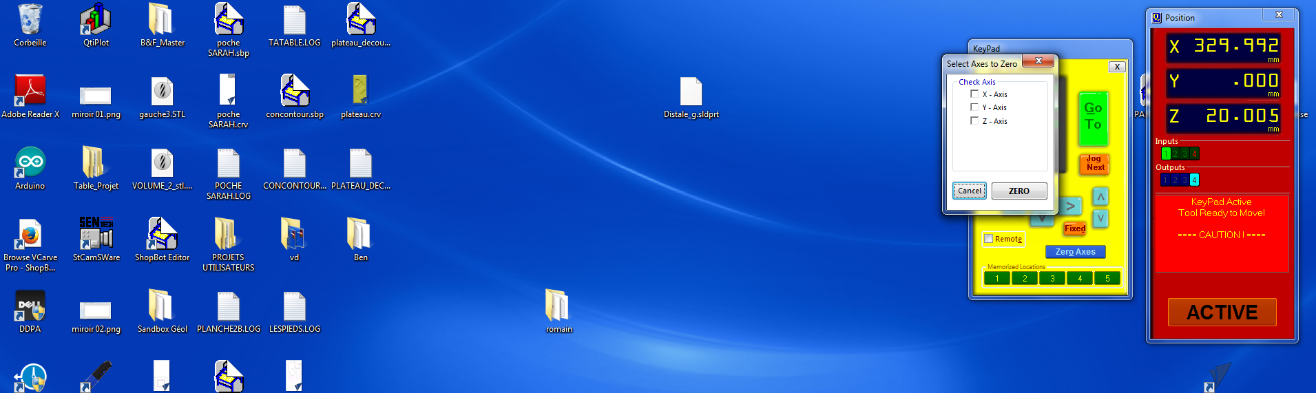 check the box you want to save. and it will change the zero of the machine.
after that you have to make the Z zero. For that you have two thing. the alligator clip and the plate.
check the box you want to save. and it will change the zero of the machine.
after that you have to make the Z zero. For that you have two thing. the alligator clip and the plate.
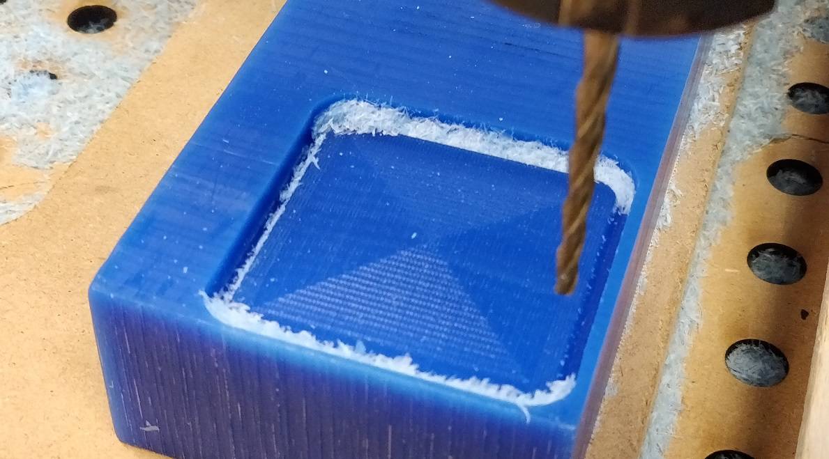
 and cut!
 When the mold is finish, it's time to Cast!
Casting Time
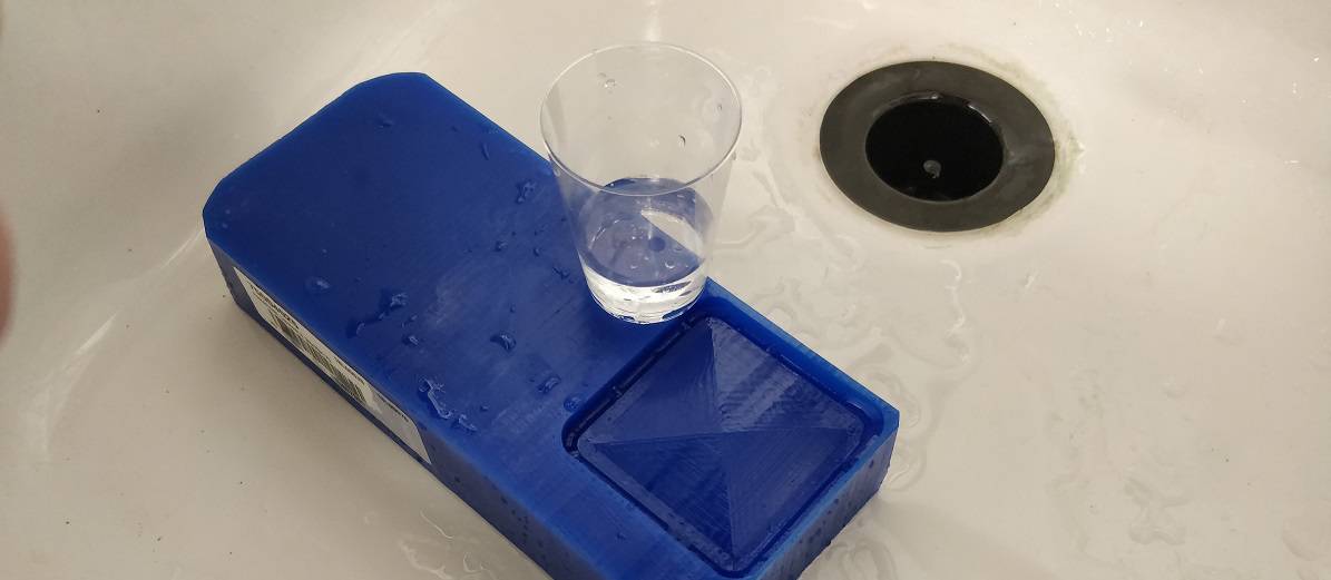
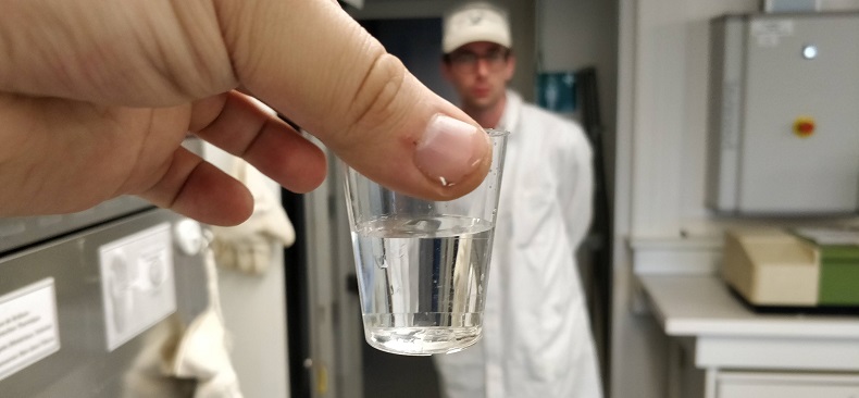
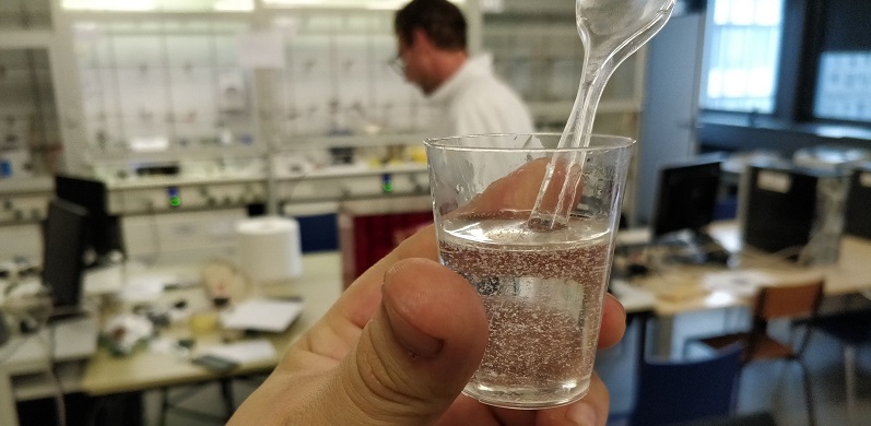
For the casting i will cast my object on silicone. For casting your object the first thing to do is to know how much volume of silicone you'll need to make.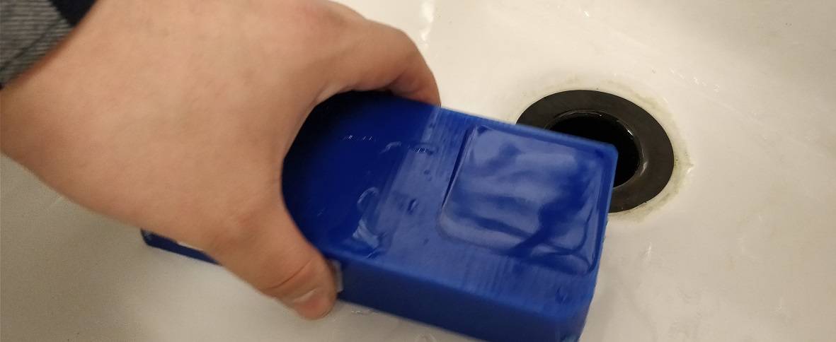 so i filled my mold with water and pour it on a cup. mark the volume of silicone i need to make.
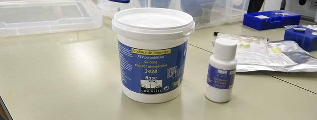
 The silicone i using is The RTV 3428, it's a Food proof silicone, in two part with a base and a catalyst
the mixe is 10:1
so for 100gr of Base, i need to add 10gr of catalyst.
The silicone i using is The RTV 3428, it's a Food proof silicone, in two part with a base and a catalyst
the mixe is 10:1
so for 100gr of Base, i need to add 10gr of catalyst.
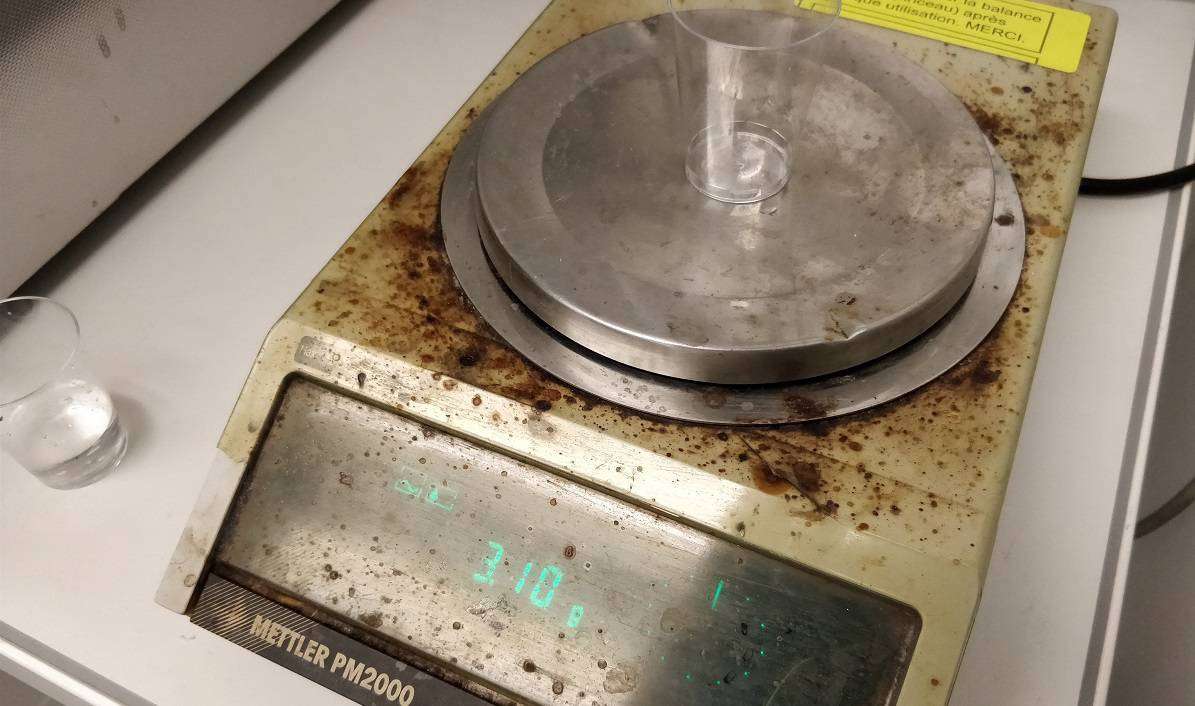
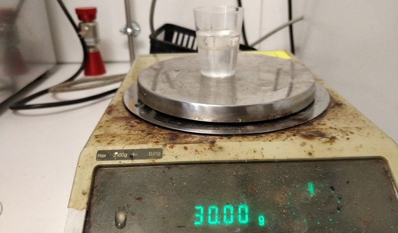
 so after i fill a new cup of the Base. the same volume of water, i measure the weight of it. (whithout the weight of an empty cup)
tare the balance and add 10 percent of the catalyst.
so after i fill a new cup of the Base. the same volume of water, i measure the weight of it. (whithout the weight of an empty cup)
tare the balance and add 10 percent of the catalyst.
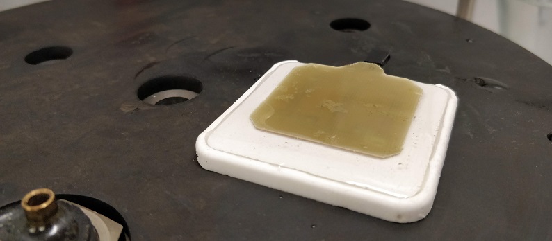
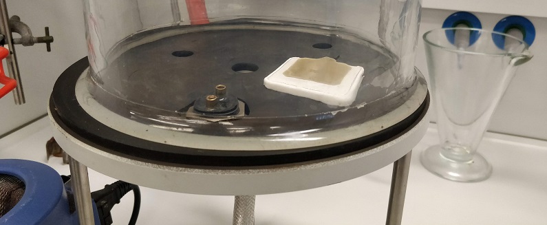
 after the mixing pour the mix into the mold and use the vaccum chamber to remove the bubbles.
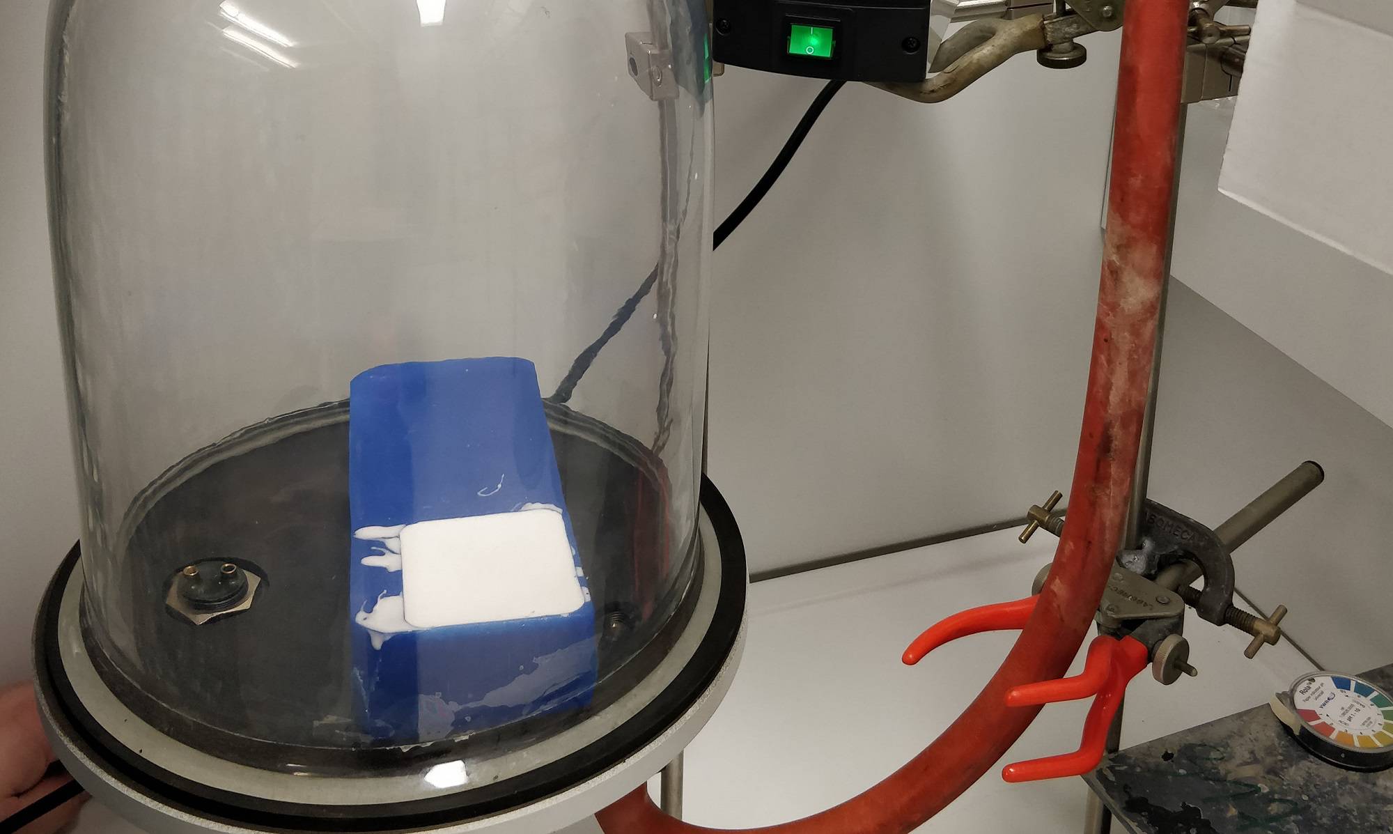 when you did that leave the Mold rest for 24 hours and voilaa!
 The next part is to pour some Epoxy on the mold
using some clear epoxy will be good.
The next part is to pour some Epoxy on the mold
using some clear epoxy will be good.
Casting Time
Now it was time to cast our mold. before that i decide to cut some led i will pour in for my final project.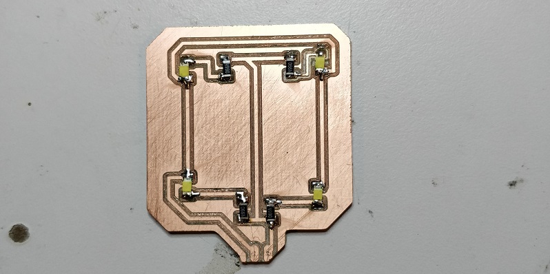 so i decide to use dome Clear Epoxy Clear
the mixing for epoxy is 50/100.
so i decide to use dome Clear Epoxy Clear
the mixing for epoxy is 50/100.
 so like i did for my silicon, i use a cup with the amount of water and mark it down.
like that i was able to know the volume of epoxy i need to make.
so like i did for my silicon, i use a cup with the amount of water and mark it down.
like that i was able to know the volume of epoxy i need to make.
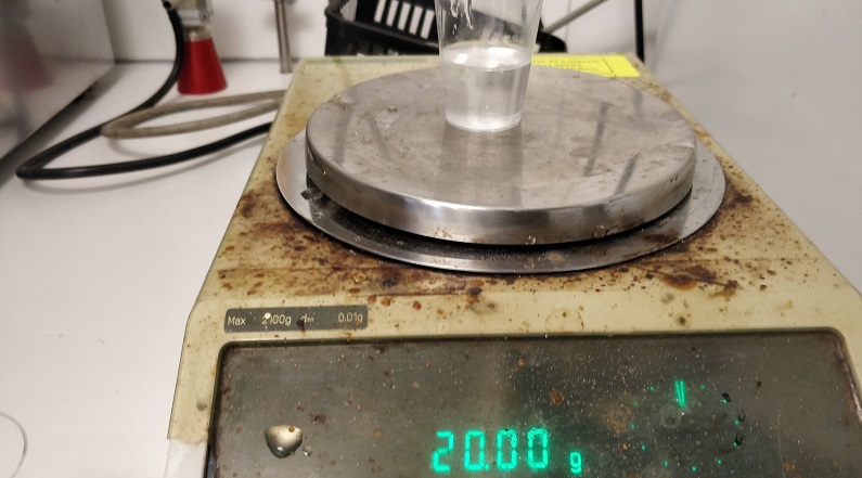
 so i pour my mix on a balance t'ill 20gr, and ad the 10 gr for the hardener.
 after that it was time to mix it, trying to insert the less air as possible inside the resin.
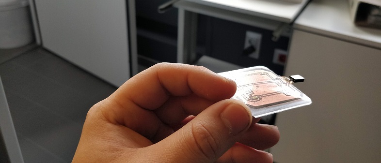
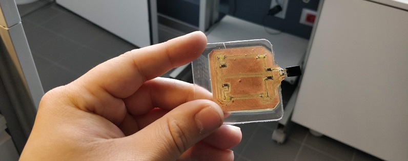
 We pour the resin inside the mold, and place my PCB inside
 then we remove the air with the vaccum chamber.
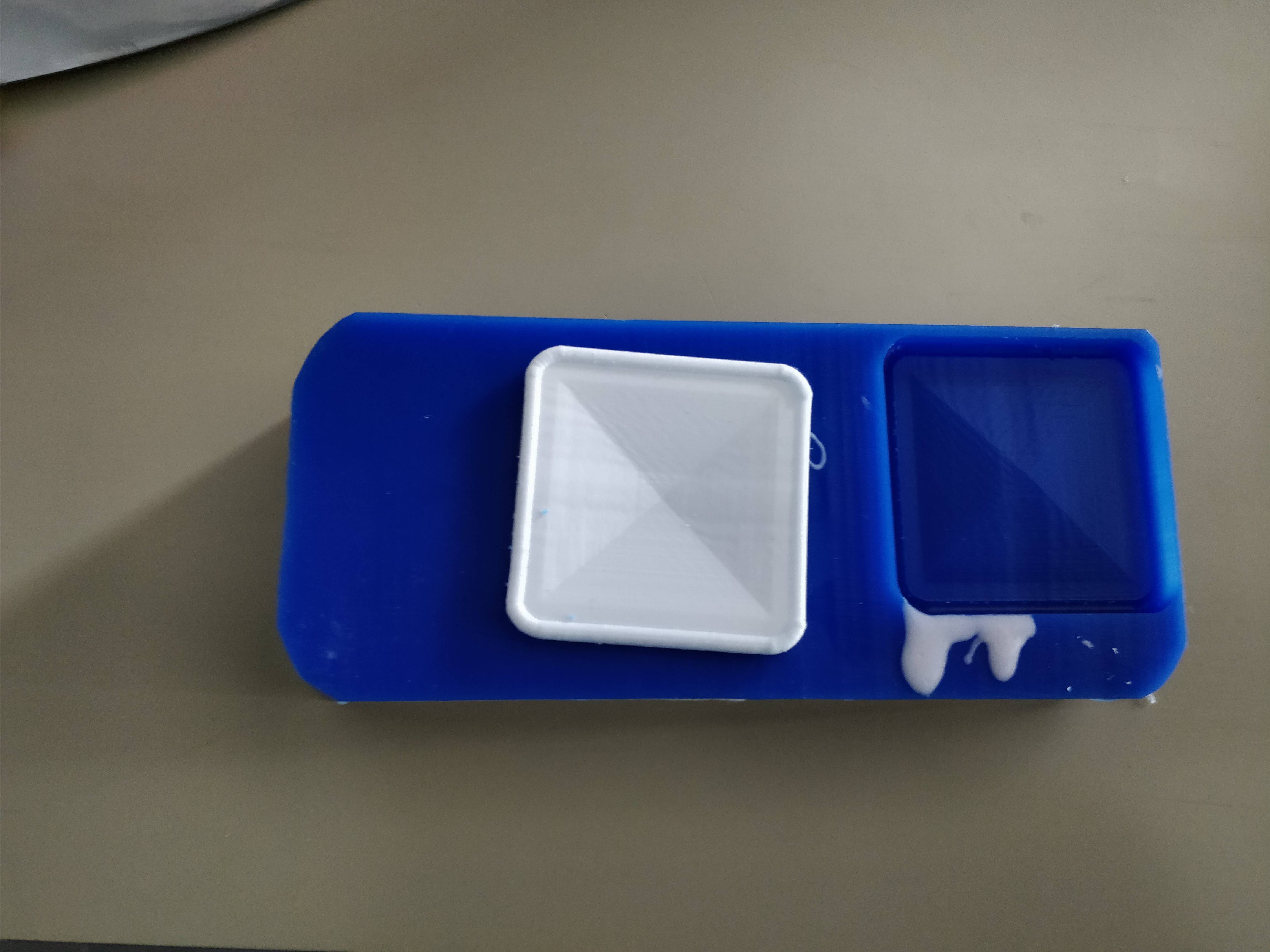
 Now it's time to let it pour 24 hours, and
Voilaa!
Now it's time to let it pour 24 hours, and
Voilaa!
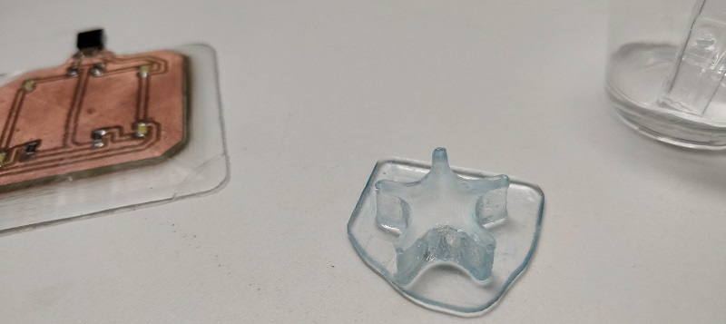
 i Also pour this small Star i cut for testing the wax parameter of cutting
 --
--
file of the week.
here you'll find the file of the week
For downloading
right click and save as- STL file (STL file)
- Fusion file (F3D file)
- VCARVE file (CRV file)