computer-controlled
cutting.
this week assignements are:
- characterize your lasercutter, making lasercutter test part(s), making test part(s) that vary cutting settings and dimensions(group project)
- cut something on the vinylcutter
- design, make, and document a parametric press-fit construction kit, accounting for the lasercutter kerf, which can be assembled in multiple ways
cut something on the vinylcutter
 for this Week project, my plan was to distinct two notebook i have. one for work, one for FabAcademy, for that i decide to look at some STM32vector i could find on google and download them.
after that i open the file with Inkscape, change the size. add some text, i converted the text to vector. export the file in DXF.
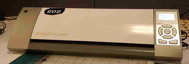
The Cameo
The Vinyl Cutter here at FabLab sorbonne univeristy is a Silhouette cameo.
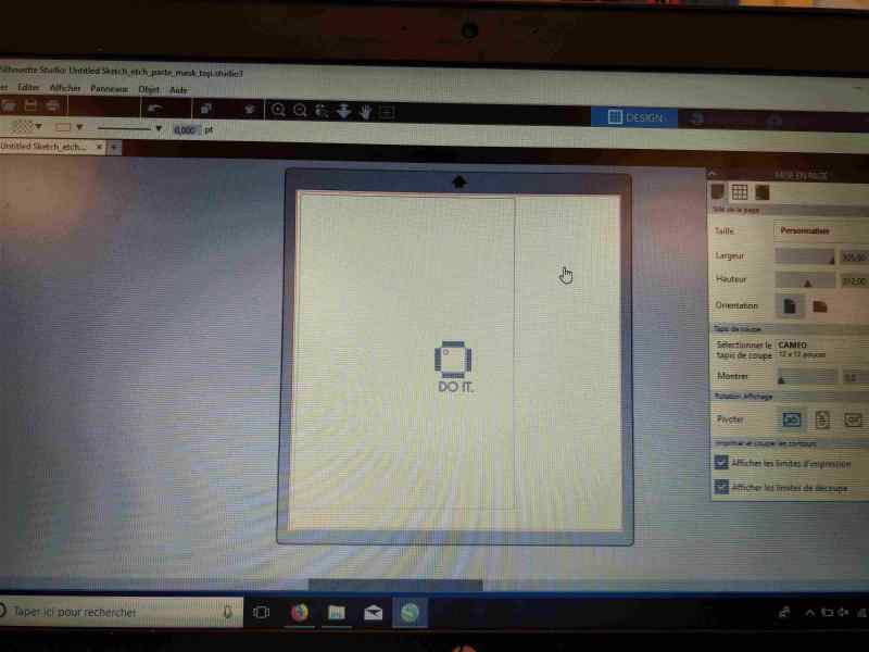
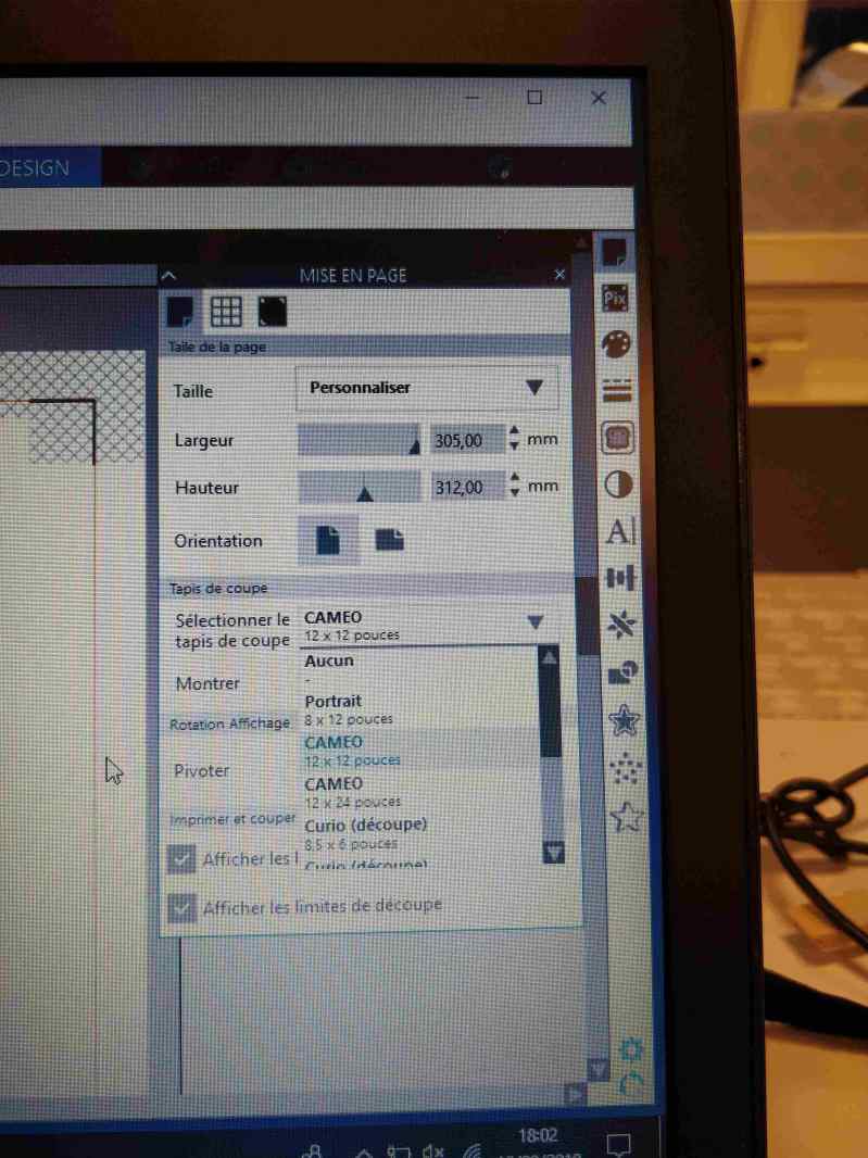
 for using it. The laser cutter you need to open your DXF file on Silhouette studio
.
for using it. The laser cutter you need to open your DXF file on Silhouette studio
.
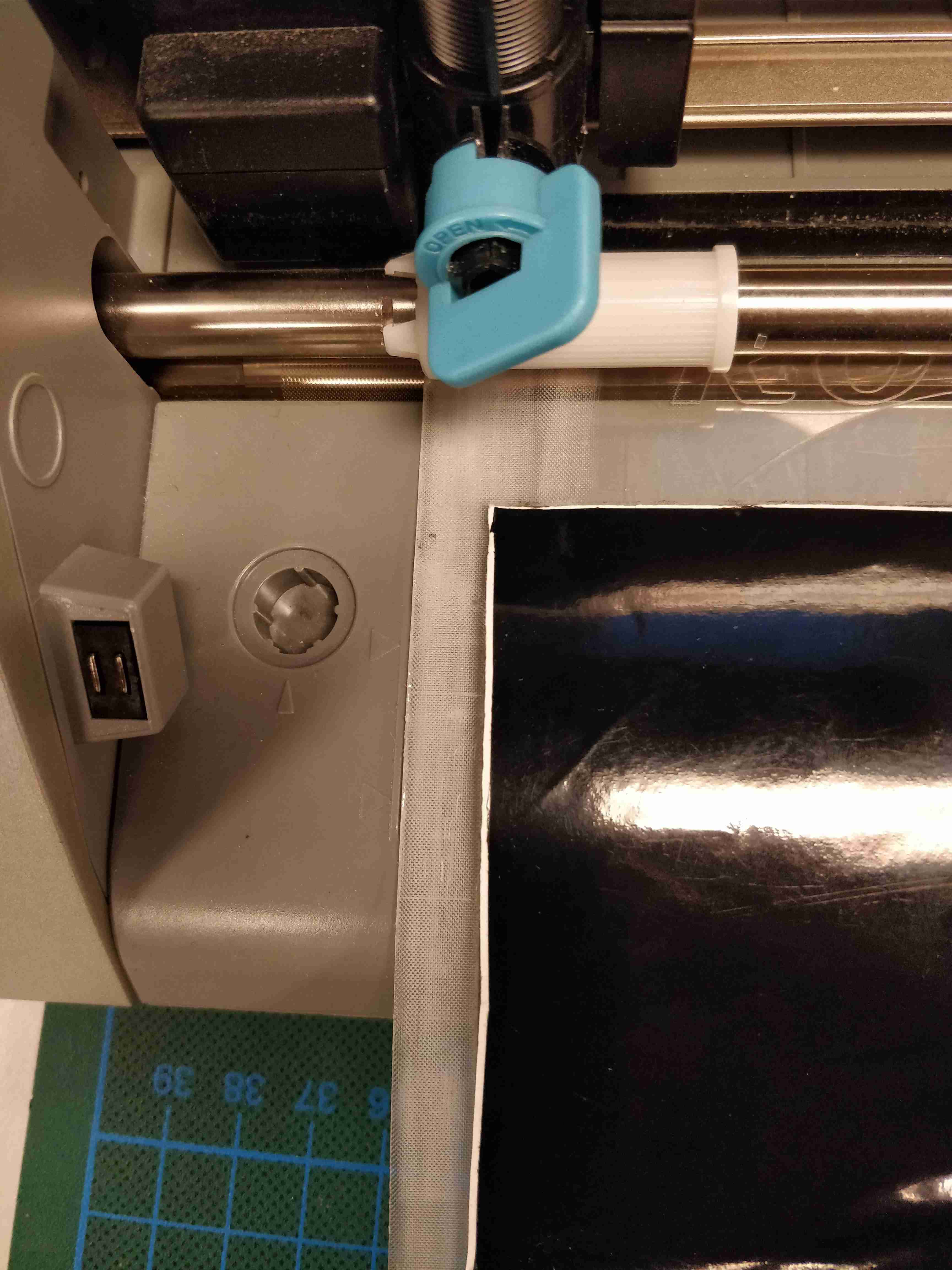
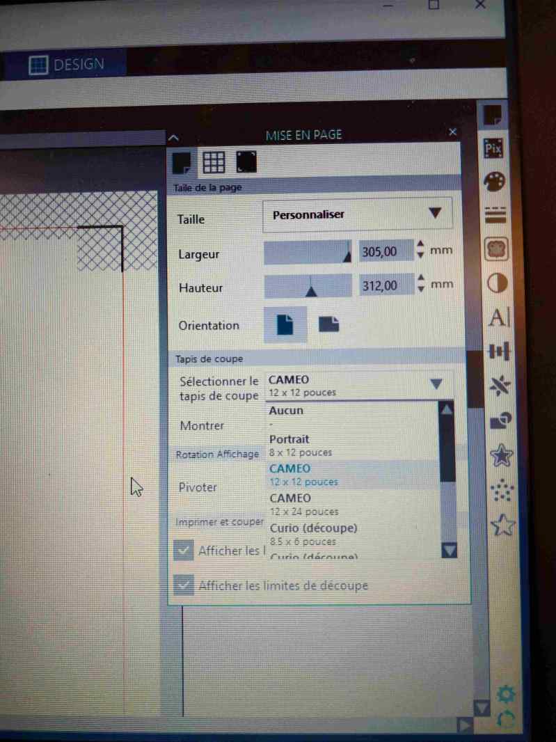 Choosing your material to cut stick your vinyl to the cuting mate when you using a cutting mate , precising witch one your using to you cameo can really make the difference.
it will give you the surface total of cutting possible with it. and be able to be more precise on you cut. the cutting mate is really easy to use. and give you more precise cut.
Choosing your material to cut stick your vinyl to the cuting mate when you using a cutting mate , precising witch one your using to you cameo can really make the difference.
it will give you the surface total of cutting possible with it. and be able to be more precise on you cut. the cutting mate is really easy to use. and give you more precise cut.
for this Week project, my plan was to distinct two notebook i have. one for work, one for FabAcademy, for that i decide to look at some STM32vector i could find on google and download them.
after that i add some small text with Inkscape like i did it lastweek and sent it to
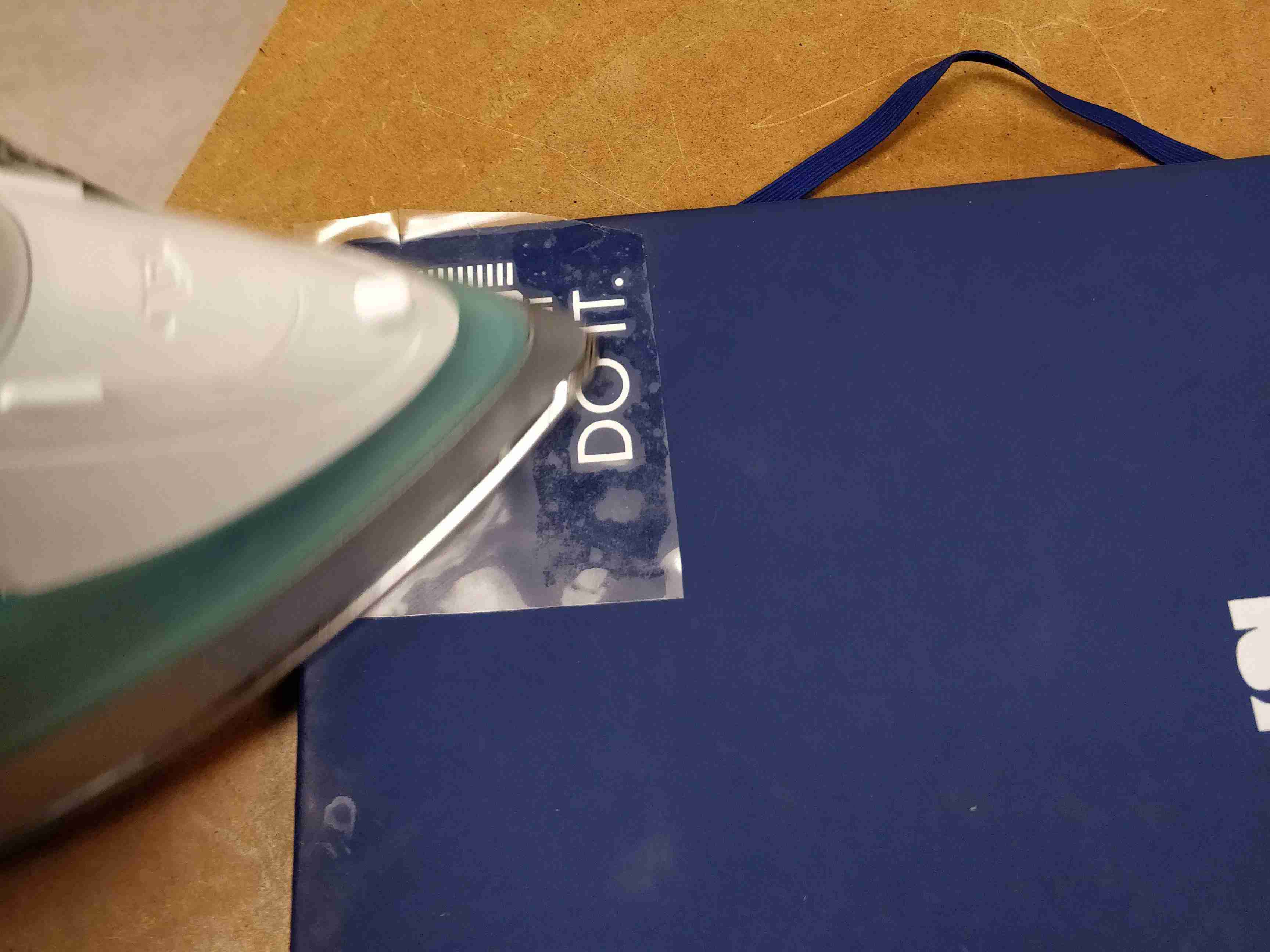
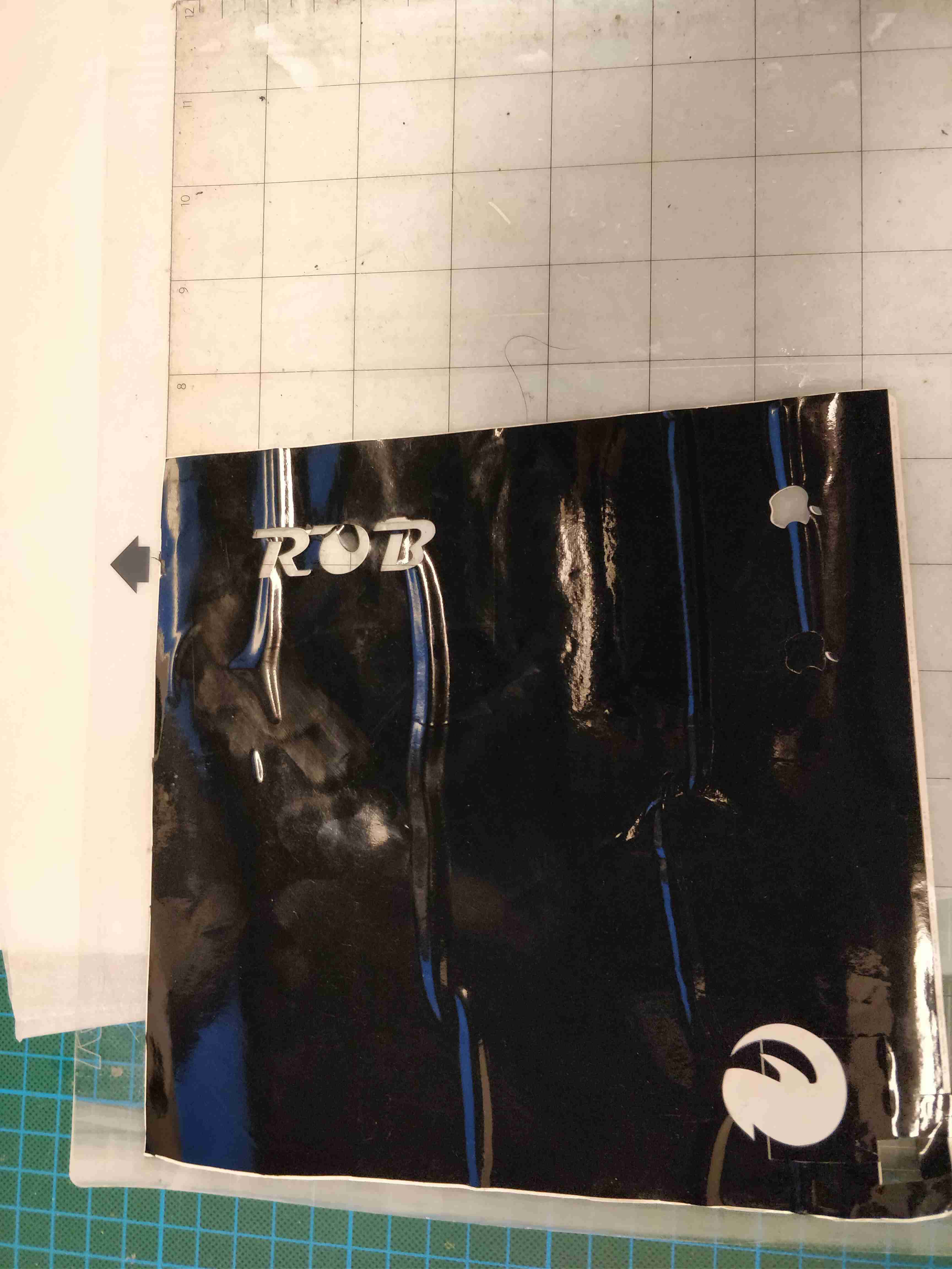
I used some flexx vinyl it's a particular vinyl that you stick on you cloth or other material, when you iron it.
when you use this vinyl you have to mirror your design and iron it inside out.

Making a parametric file
This week i discoverd the power of parametric file. This was really great to learn how to make it. Really simple with Fusion360 a function exist named "Change parameter" With that i was able to make my own pressfit construction kit


THe laser cutter.
The laser Cutter of FablabSorbonne University is a trotec 300.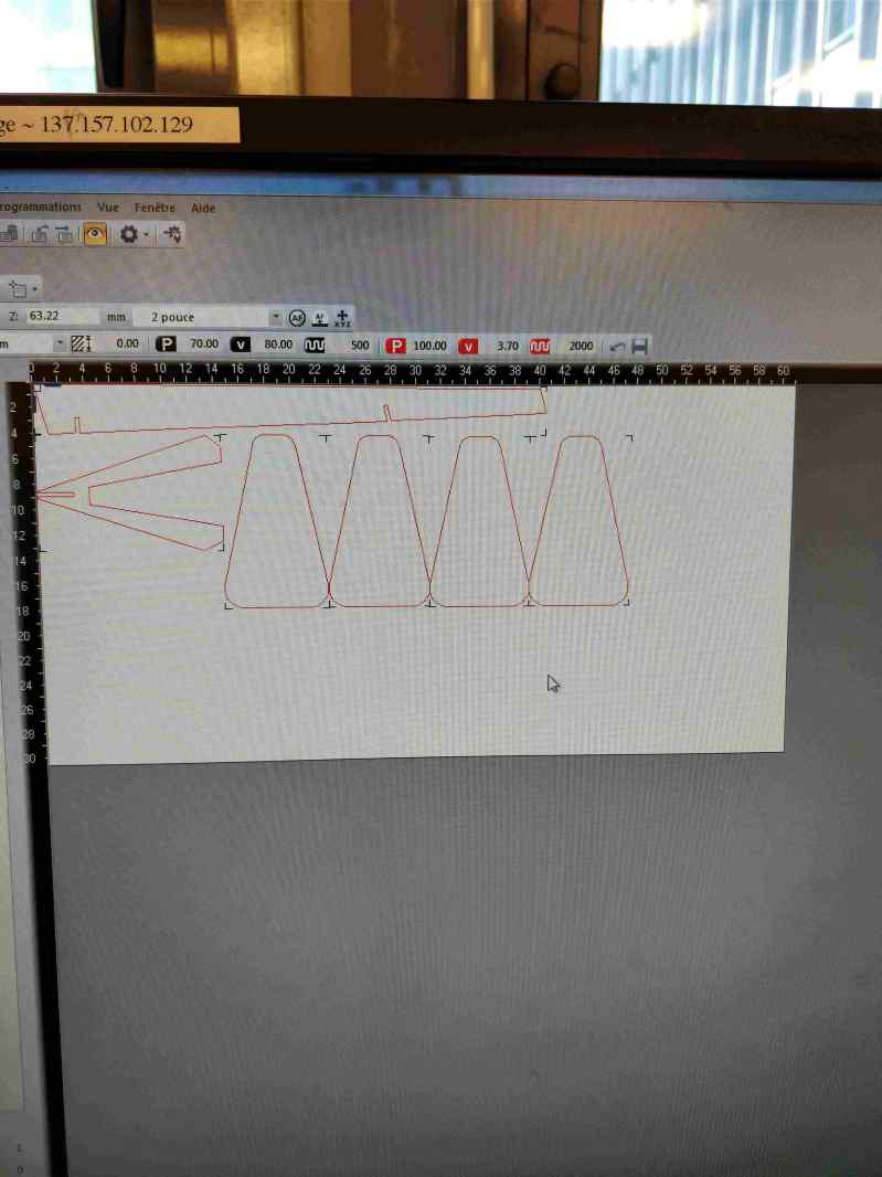 for cutting and ungraving a file in this laser sent on the spooler of the laser cutter specific type of file.
these file need to be:
for cutting and ungraving a file in this laser sent on the spooler of the laser cutter specific type of file.
these file need to be:
- Red 255,0,0 OUTLINE for cut
- No filling for cutting
- Black color is for for engraving
- Red line need to be 1px large. When your file is ready, you have to clic on print choose the TROTEC300 in the spooler then clic on print. it will open the job control spooler where you'll find your file. just take it. drag and drop it on the table of the laser and
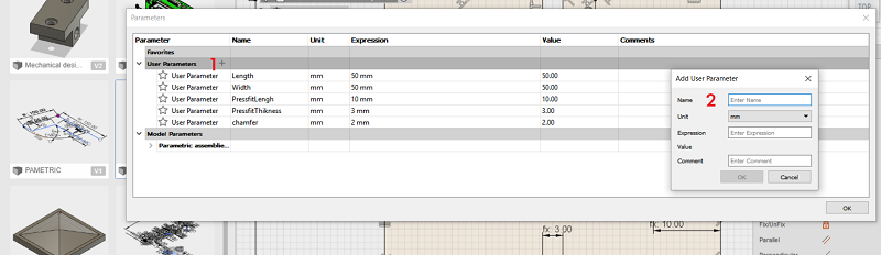
- name) the name you give to your new parameter
- unit) it can be inch, millimeter, degres, temperature, a currency, or a percentage.
- expression) it the "real" value. it the place when you'll have to change the size of your object for exemple, you will modify.
- 1) here you have to click to create a new parameter
- 2) this is the new parameter window.
- Vector file for the vinyl cutter(DXF file)
- Record booth parametric(fusion360 file)
- Parametric assemblies (Fusion360 )
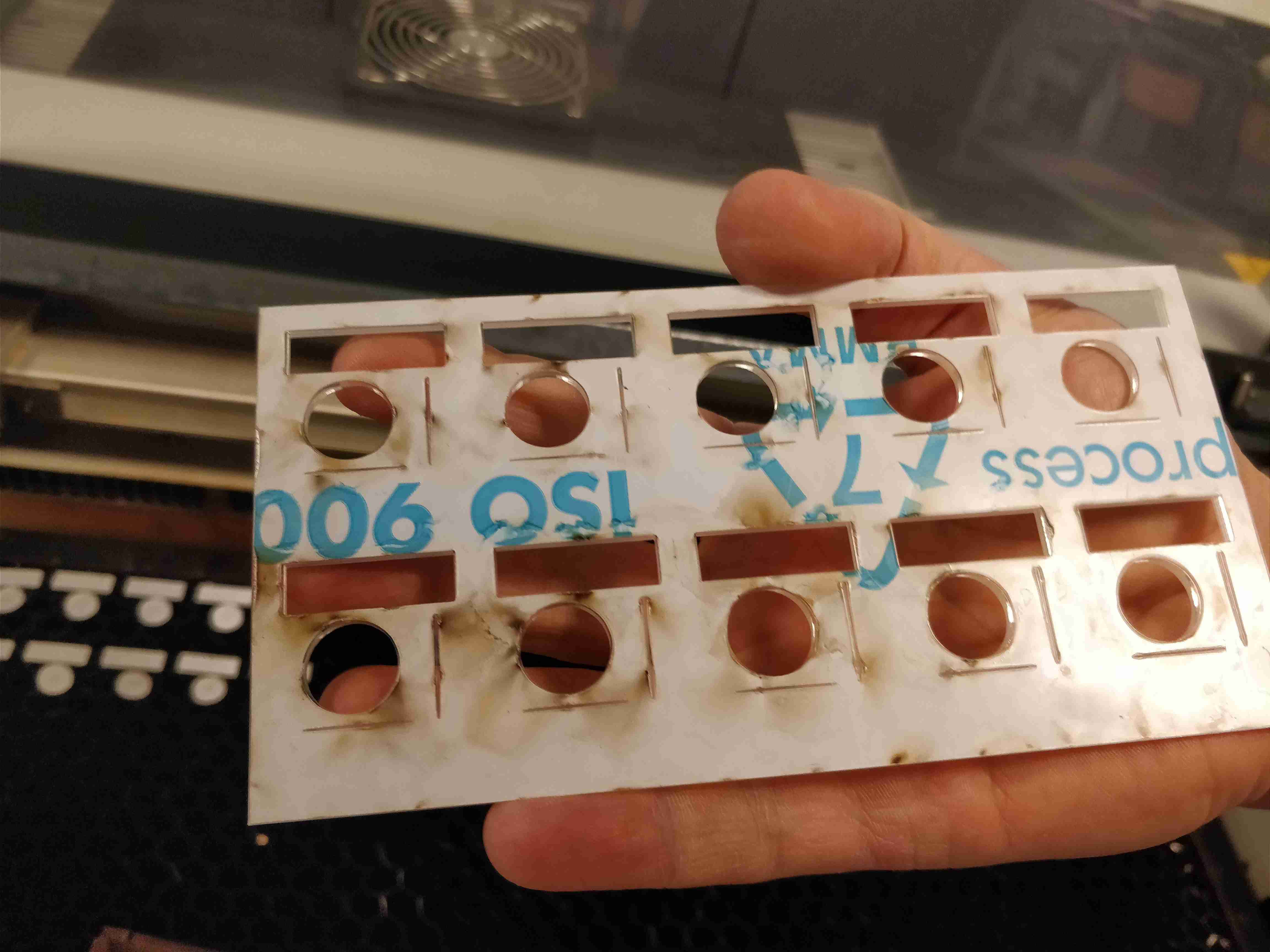
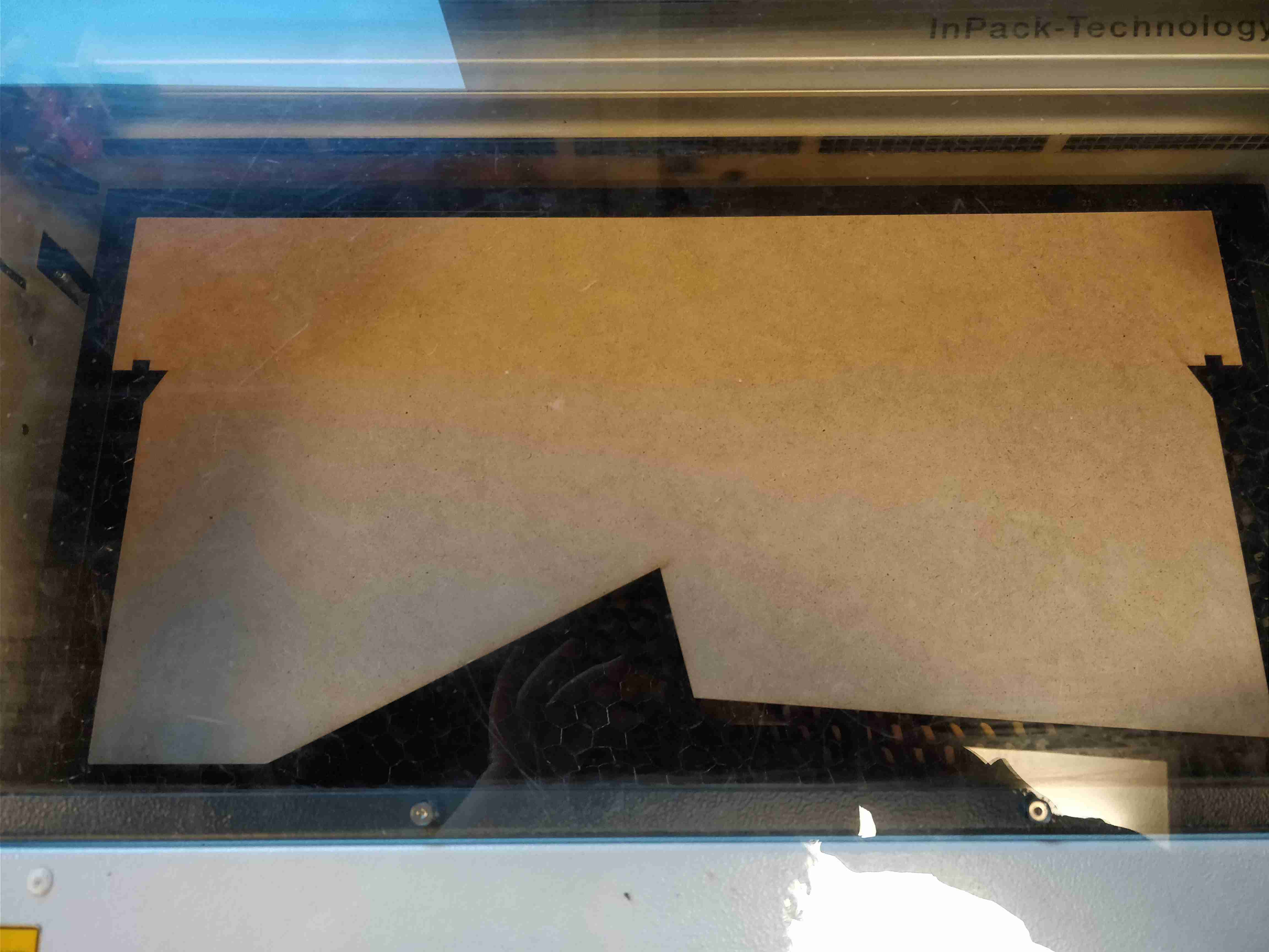
 Making the lens focal for cutting MDF
Parametric design
For this week we had to learn to use parametric design. i came from Sketchup so i didn't know what that means first. but i discoverd the power of this way to design an object.Parametric design is great for prototyping, if you need to change some value really quickly.
making Parametric design on fusion360 is really simple, you have to open "modify" pannel and click "change parameter"
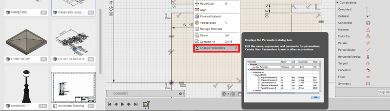 a window will open with different categories.
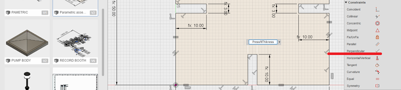
constraints
Making the parameter is nothing if we don't apply any constraints on our project. constraints make the design staying the same, after changing value.but no enough constraints and your object won't work if you modify some value. Overconstraint(fusion prevent from that), your object won't be able to change. when your project having not enough constraints, it will have some blue line.
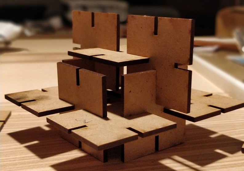
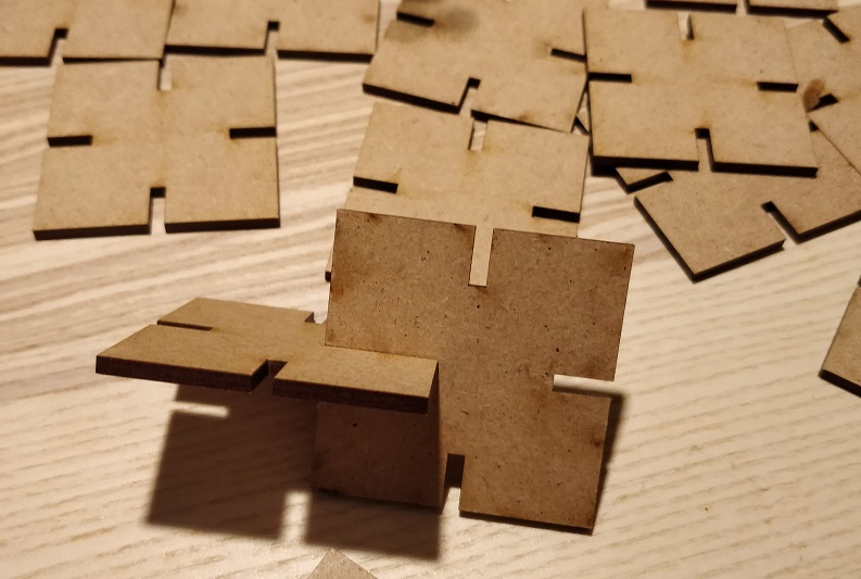
so with that i was able to cut my first parametric piece! and assemble some of it for having a pressfit result!
Troubleshooting
Parametric design was a big part of my learning and Troubleshooting this week, how to make them, and how to apply it to my own design. i tried to make a small scale of the record booth with only parametric design., and time started to fly so i decide to make some pressfitsquare. but my final project is almost done in parametric design.
What i've learned
Parametric design again, big part of my week, really a new way to think how i'll make 3D/2D file now. Clearly. Presfit design was really interessing never took the necessary time to explore it, this week was perfect for read more about it! --
file of the week.
here you'll find the file of the week
For downloading
right click and save as
More picture