Week 9: Embedded programming
Group assignment:compare the performance and development workflows
for other architectures
Individual assignment:read a microcontroller data sheet
program your board to do something,
with as many different programming languages
and programming environments as possible
Learn
In the first datasheet's page there is a list of the microcontroller's features, like:
- 12 programmable I/O Lines
- One 8-bit and One 16-bit Timer/Counter
- Programmable Watchdog Timer with Separate On-chip Oscillator
- Operating voltage: 1,8v - 5.5v
- Speed Grade: 0 - 4 MHz , 1.8 - 5.5V 0 - 10 MHz , 2.7 - 5.5V 0 - 20 MHz , 4.5 - 5.5V
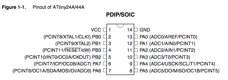
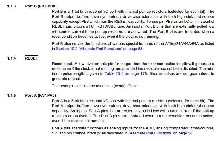
The second page of the datasheet is about pin description so you can know the function of every single pin. I even knew that VCC is voltage and GND is ground, but the rest of the information is new to me
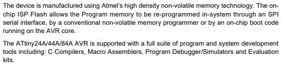
I found interesting this part of the data sheet because it gives some information about the flash memory so I can understand better how it works
A more complete explanation about how the three types of memory work are on page 15, the one in the image below is a brief.
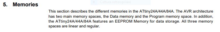
So an AVR microcontroller (which is pratically a very small computer) has three types of memory:
Flash memory: this is the non-volatile memory where your coding gets stored and that doesn't disappear when power goes off;
RAM memory: volatile memory for temporary variables storage;
EEPROM memory: slow-to-write-to and configuration settings memory that remains after power goes off.
Go on the datasheet I read this information
That makes it sense because I read the part which said "the ATtiny24A/44A/84A achieves throughputs approaching 1 MIPS per MHz allowing the system designer to optimize power consumption versus processing speed" and the microcontroller has One 8-bit and One 16-bit Timer/Counter.
What remains to be explored
The toolchain
Writing the source code
Compilation
Execution
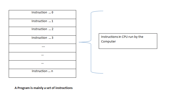
So basically a program is a set of instructions that the computer executes. (To be more precise, a program is a set of instructions loaded in the CPU that the CPU executes to achieve an outcome).
Arduino IDE
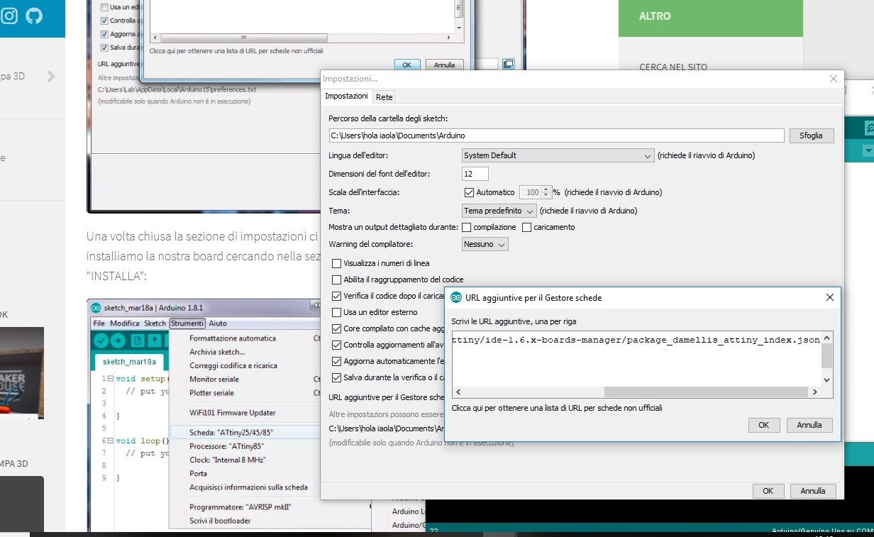
I chose to use Arduino ide because it simplifies the steps of the toolchain. To be able to program an AtTiny 44 with this software I discovered in this link that I had to copy a specific url in the board manager, in this way it would have appeared the right microprocessor in the list. So I opened settings and pasted this URL
https://raw.githubusercontent.com/damellis/attiny/ide-1.6.x-boards-manager/package_damellis_attiny_index.json
in this space
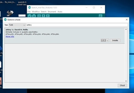
then I went to sketch -> include library ->library management to install the new library
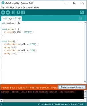
with the tutorial of arduino IDE I tried to do the blink sketch. those are the things I learned:
int = Integers are your primary data-type for number storage.
in this case we use it to define our output pin, in this case the 5 pin.
digitalWrite = Write a HIGH or a LOW value to a digital pin. If the pin has been configured as an OUTPUT with pinMode(), its voltage will be set to the corresponding value: 5V (or 3.3V on 3.3V boards) for HIGH, 0V (ground) for LOW.
If the pin is configured as an INPUT, digitalWrite() will enable (HIGH) or disable (LOW) the internal pullup on the input pin.
Delay = Pauses the program for the amount of time (in milliseconds) specified as parameter. So this is my sketch, but somethin went wrong.
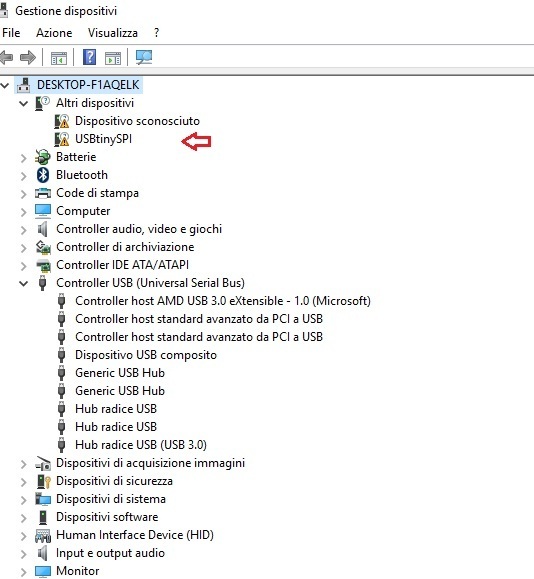
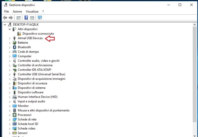
so I installed this drivers (Download here). And now Windows can see my board.
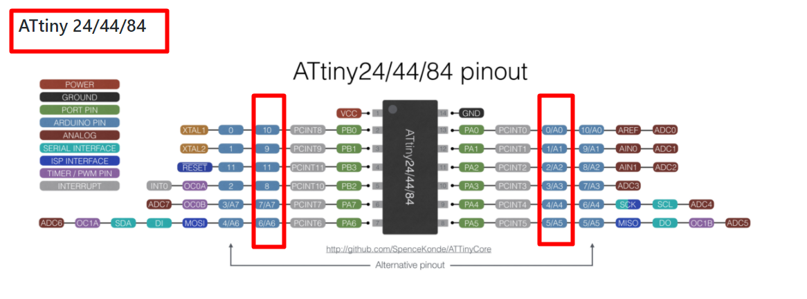
but the sketch still does not work. Asking for help in the lab Pietro Rustici suggested me to check if the reference pin was right. And in fact I confused the pins, the right pin was not 5 but 8.
Now the problem seems to be "error when writing the bootloader".
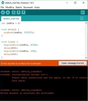
Asking suggestions, Pietro Rustici explained that the first time you program a board with Arduino ide you have to do burn bootloader. To better understand the reason for this procedure I searched on the internet and I found this page that explains:
"On power-up or reset, a bootloader is a section of program memory that runs before the main code runs. It can be used to setup the microcontroller or provide limited ability to update the main program’s code. this time the sketch told me that the problem was the bootloader.
The Arduino bootloader supports re-programming the program memory (or Flash) over serial".
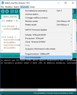
So I did ->tools ->write the bootloader. Moreover, as you can see from the image I have set up the sketch loading in this way:
Board = AtTiny 24/44/48
Processor = AtTiny44
Clock = External 20 MHz
Programmer = USBtinyisp
upload through a programmer

and the board started to blink!
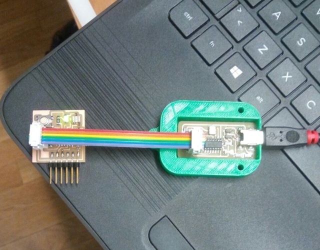
I have to say that the programmer that I used was not mine because apparently it does not work anymore, but I realized another one, see Week 4
Update 03/06/2019
Under suggestion of my instructor Matteo I decided to program my board with a Makefile, in order to deeply understand the toolchain. I followed this tutorial to start my programming in C.
Since I used Notepad + + in Week 4 I opened a new file, copied and pasted the makefile example I found here and I started do modify the file.
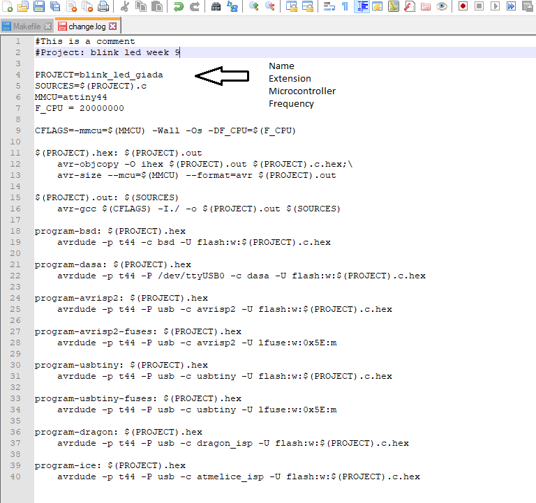
But at the end of the tutorial it talks about "fuses", and though it isn't the first time I saw them I never discussed the subject in depth, so I searched for some information and I read the explanation here (this link is very useful since it contains a table with the fuses for AtTiny44 and the corresponding datasheet page). In practice there are 3 type of fuses ('fuse low byte', 'fuse high byte' and 'fuse extended byte') which can be reprogrammed as many times as you want and their value is not erased when the chip is powered off or reprogrammed. I followed the tutorial quoted before but it wasn't clear for me what parts of the makefile to consider, so I looked at the documentation of my mate Dario and I saw I had to delete some part of the makefile. Moreover I saw this link which explain how the internal clock works:
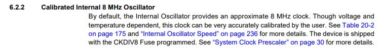
"CLKPS[3:0] gets initialized by default to 0011 (which is the value for 8 - note that this is not a binary to hex conversion) from the CKDIV8 LFuse, which by default is set to CKDIV8 (CLocK DIVision 8). By default, the 8MHz Internal RC Oscillator is selected as clock source from the CKSEL[3:0] LFuse [...] The clock speed therefore is 1Mhz, i.e. if we tell the compiler in the Makefile with F_CPU = 8000000 that the chip runs at 8MHz, everything will be executed 8x slower than we expect."
So I used the calculator in this page where if CKDIV8 isn't selected we gain the right low fuse values.
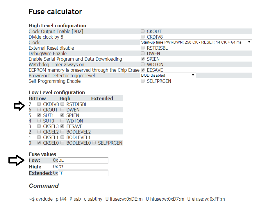
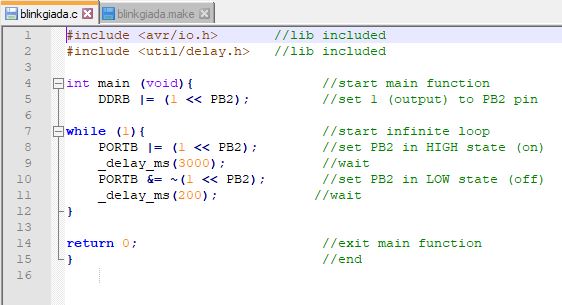
So I changed the fuse's value
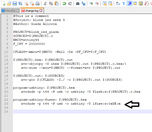
Then I saved the file in a folder on Desktop and copied and past the code from the prevoius documentation, but modifing the delay.
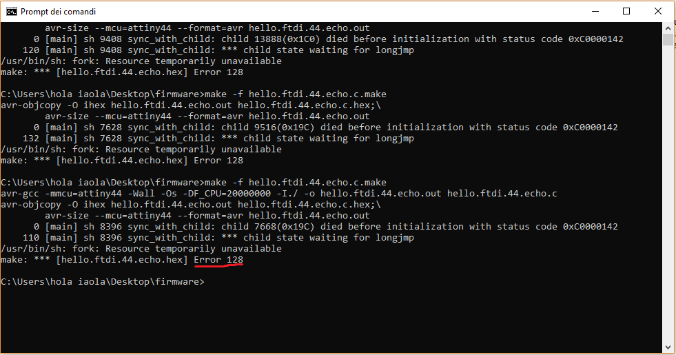
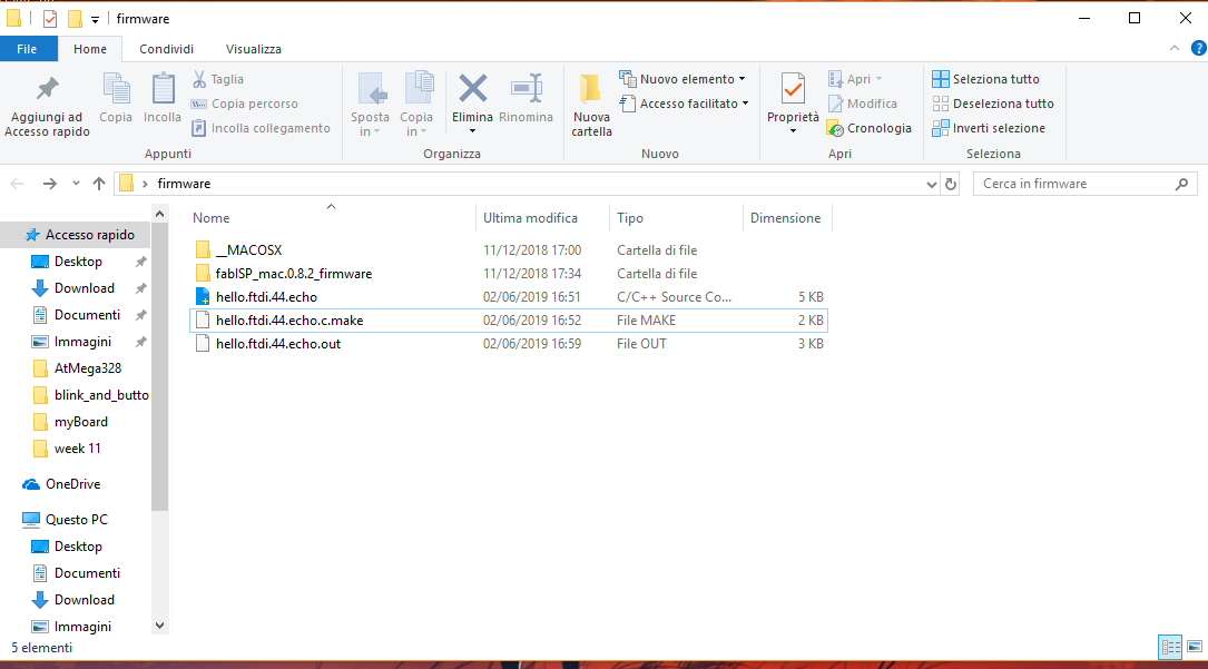
Then I opened the terminal, went to the directory and typed make -f blinkgiada.make in order to create blinkgiada.hex and blinkgiada.out but the files didn't appears. I tried several times but it always gave me this error
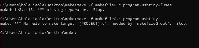
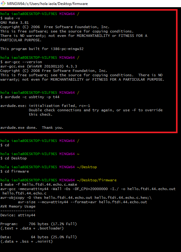
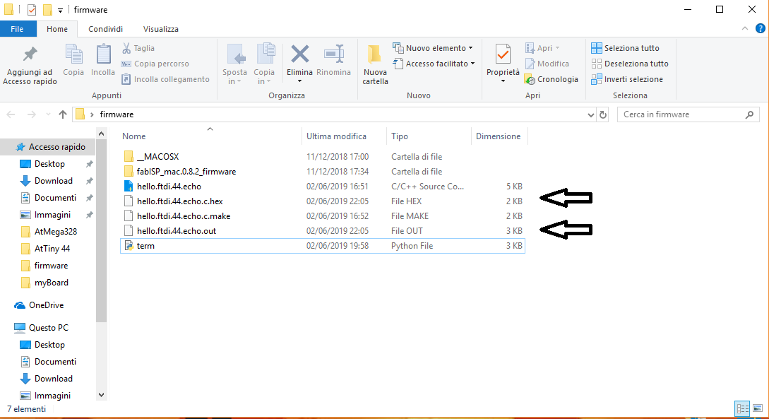
Since I already had all the programs installed for the toolchain I didn't bother to check that they were working or not, so I started to think that maybe I should just update some software. I re-made all the steps I did in Week 4 and followed this instructions. Then I checked if all the programs worked with those commands, that you can see in the first part, I entered in the directory and inserted the make command and finally it worked.
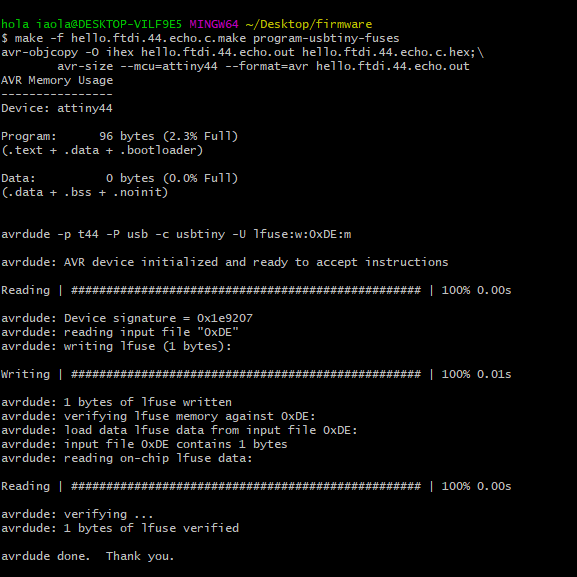
make -f hello.ftdi.44.echo.c.make program-usbtiny
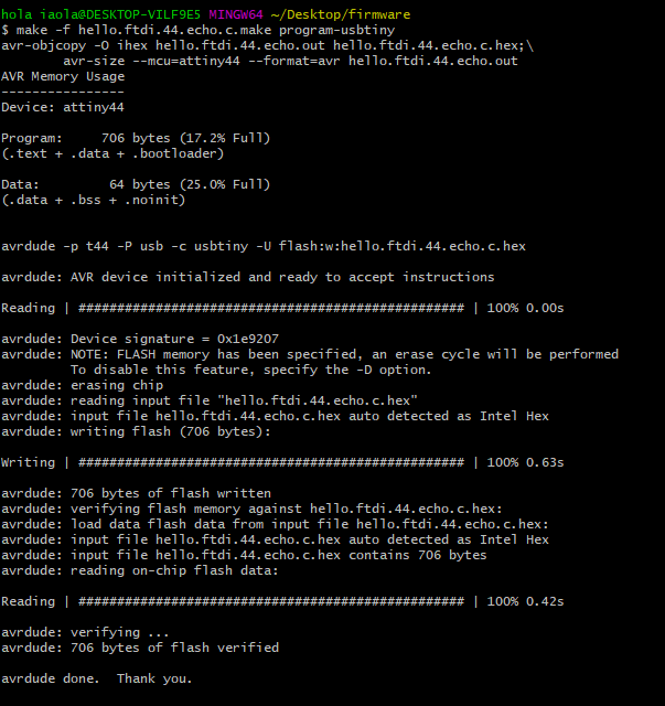
And this is the final result