Week 4: electronics production
Group assignment: characterize the specifications of your PCB production process. Here the link
Individual assignment: make an in-circuit programmer by milling the PCB, then optionally trying other processes
Individual assignment: make an in-circuit programmer by milling the PCB, then optionally trying other processes
Make an in-circuit programmer
This week we have to create our programmer, so we have to choose one and redo iT ex novo (or almost) I have chosen the Brian's FabISP
because has a complete documentation and tutorials in his page.
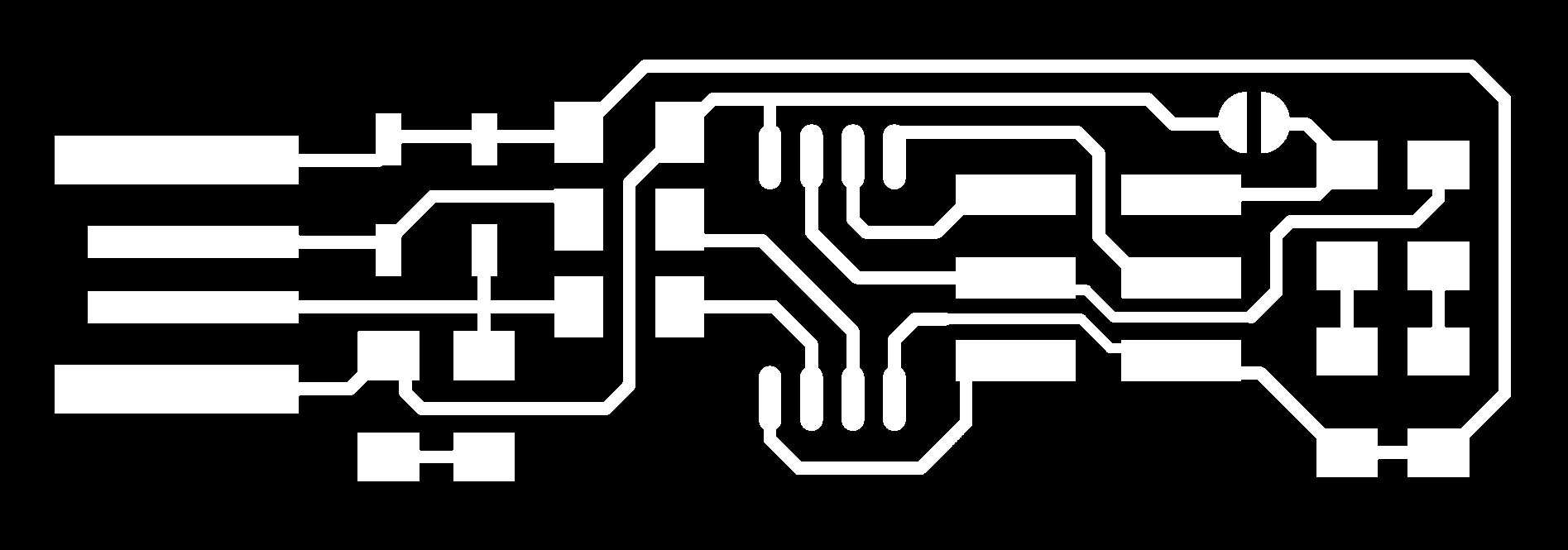
Basically, what I did was to download .png files of the ISP and use them in fabmodules.
Below the files (traces and board outline) I looked for:
After downloading the images I have followed the following steps in order to create the files that Roland will run.
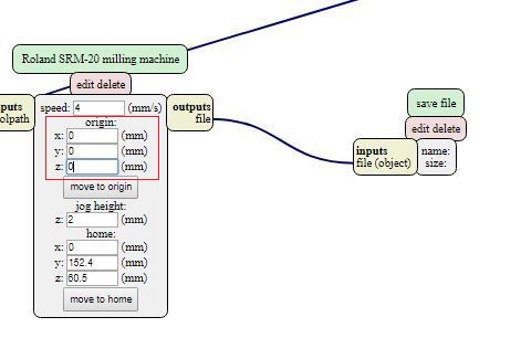
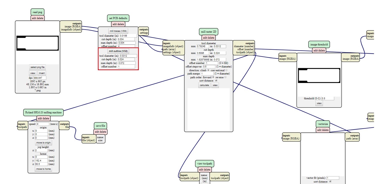
First I opened a new fabmodule and went on Programs ->Open server program-> Machines->Roland->mill->SRM-20->PCB. Then I deleted the part circled in red.
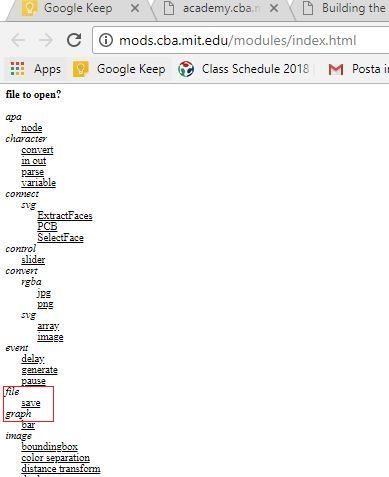
Than Modules - Open server module - File (save).
I connected the new "File - save" module. Than I open my .png traces file clicking on select png file. In the second module I selected mill traces 1/64 (the size of the tip to make traces).
It is important to set all origins to 0.
when all the parameters have been set correctly, just click on calculate and the program will automatically save the file. After the file for the tracks has been saved you have to make the cut file: then load the png file and this time choose the mill outline option
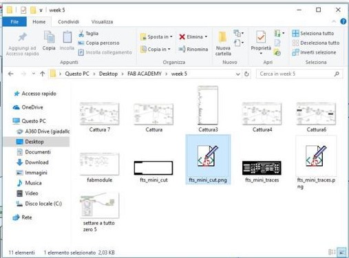
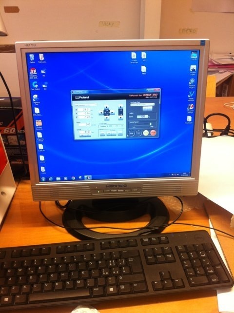
then I took the files and moved them to the PC connected to the Roland
In out lab we have the Roland SRM-20
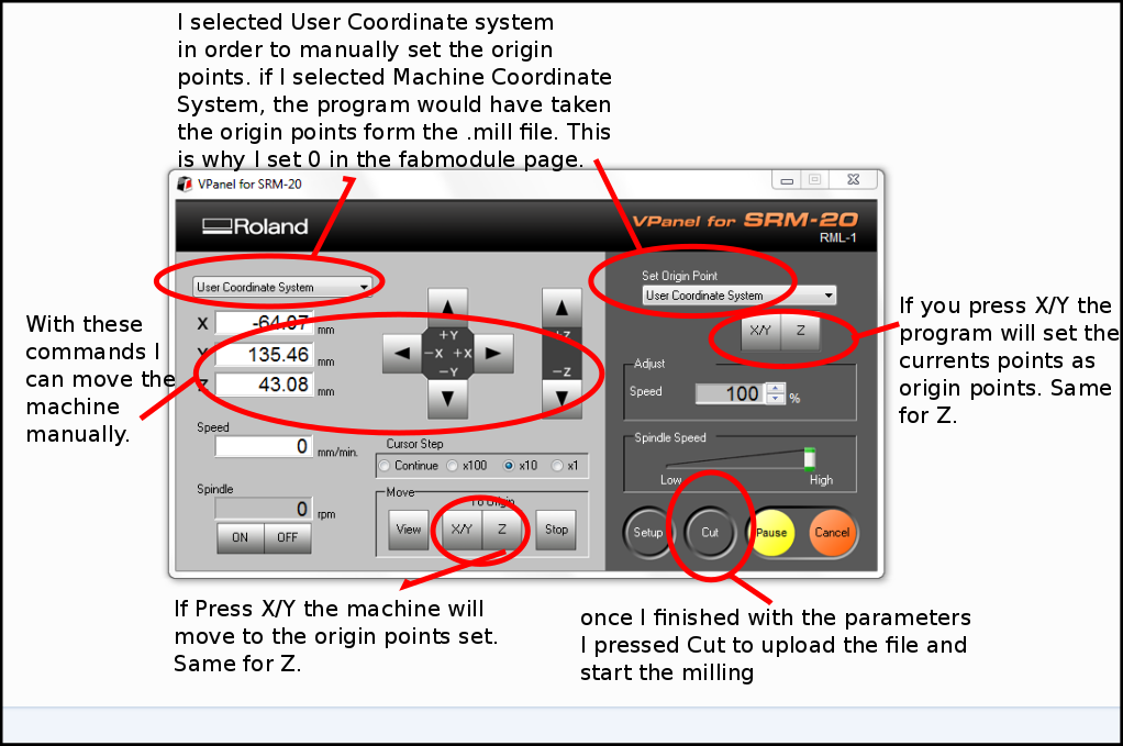
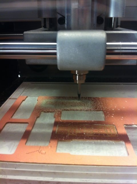
In the lab we have a roland SRM-20. To create the tracks you have to use a very fine (1/64 of) and be very careful because if it falls may break. Once inserted the tip, you have to stick firmly the PCB so it will not move during the cut. Through the program of the machine you can set the origins and give the cut command.
As you can see this is the panel to control our Roland and the instructions. The image is from Flavio Lampus's documentation. To start the milling I used the thinner tip, that is the one from 1/64. In this operation it is essential to be very careful not to drop it because the tip is very thin and could break. Once the tip is secured I set the origins via the control panel. For the Z origin it's necessary to do the operation with caution, in fact you have to make it go down very slowly near the base up to a distance of a few millimeters. At this point I unscrewed and placed it on the PCB with a slight downward pressure to prevent it from getting up while holding the support. At this point you have to go on the control panel to enter the Z. Once all the origins are set correctly, just press on cut to select the file that has to be milled.
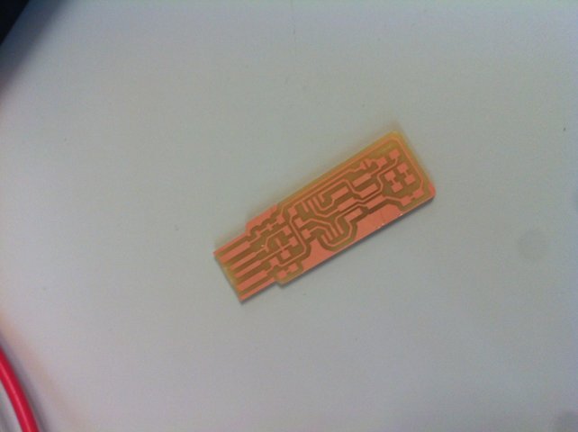
Once the milling of the traces was over, I cleaned the residues and I repeated the operation to make the external cut, this time using the 1/32 tip. Once this operation was completed, I unplugged my board and washed it to remove any residues that could compromise the soldering.
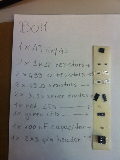
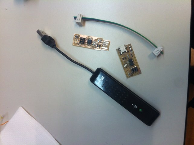
before soldering I took all the necessary components for the board (BOM)
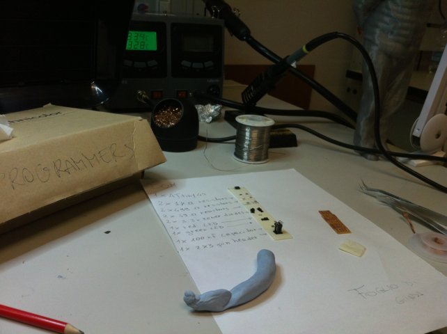
Once I got all the necessary elements and have become familiar with the location and the tools I started to solder. To help myself I took a box found in the laboratory as a support and I fixed the board with patafix to have more stability during welding.
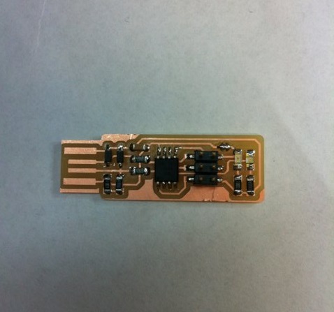
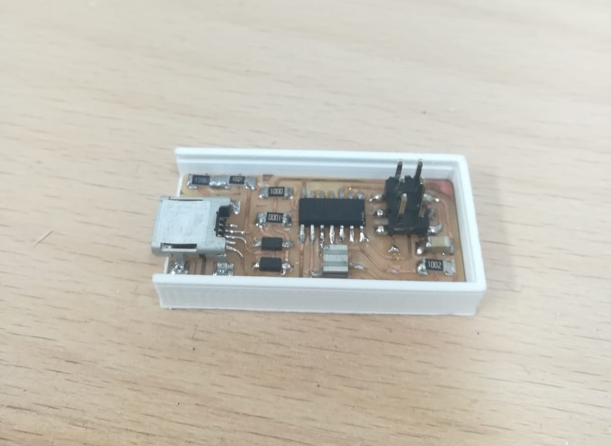
I must say that I had a lot of fun soldering, although at first it was difficult to keep the pieces steady because of their tiny size, and I'm quite satisfied with the result. Another key factor is to be careful not to heat the solder tin too much, otherwise it will not conduct electricity anymore and this would ruin the board.
To program my ISP I followed the instructions suggested by Brian in its
documentation ,
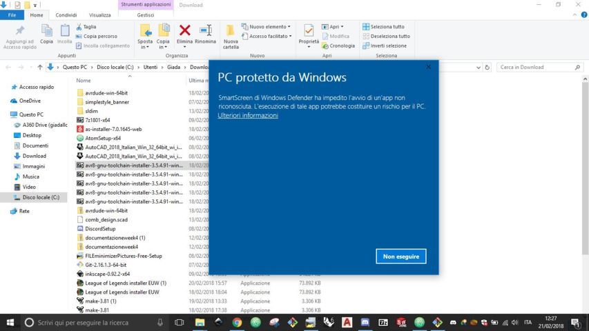
specifically those for Windows 10. I downloaded and installed all the programs, but at some point windows created problems with
one of them.
The text says: "Windows defender SmartScreen prevented the initiation of an unrecognized app. Running this app could pose a risk to your PC".
So I used the Tommaso Lombardi's PC to program my board, since he did the same board, so the steps were the same.
Run Make Flash
Run Make Fuses
Luckily everything went fine and the programmer was succesfully programmed.
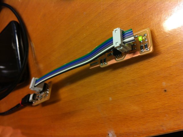
this is the test to check the fabISP
the tutorial recommends to remove the solder from the jumper so is not possible to reprogram the board
Unfortunately my programmer broke down, so I created a new one. This time I did the FabOptimus.
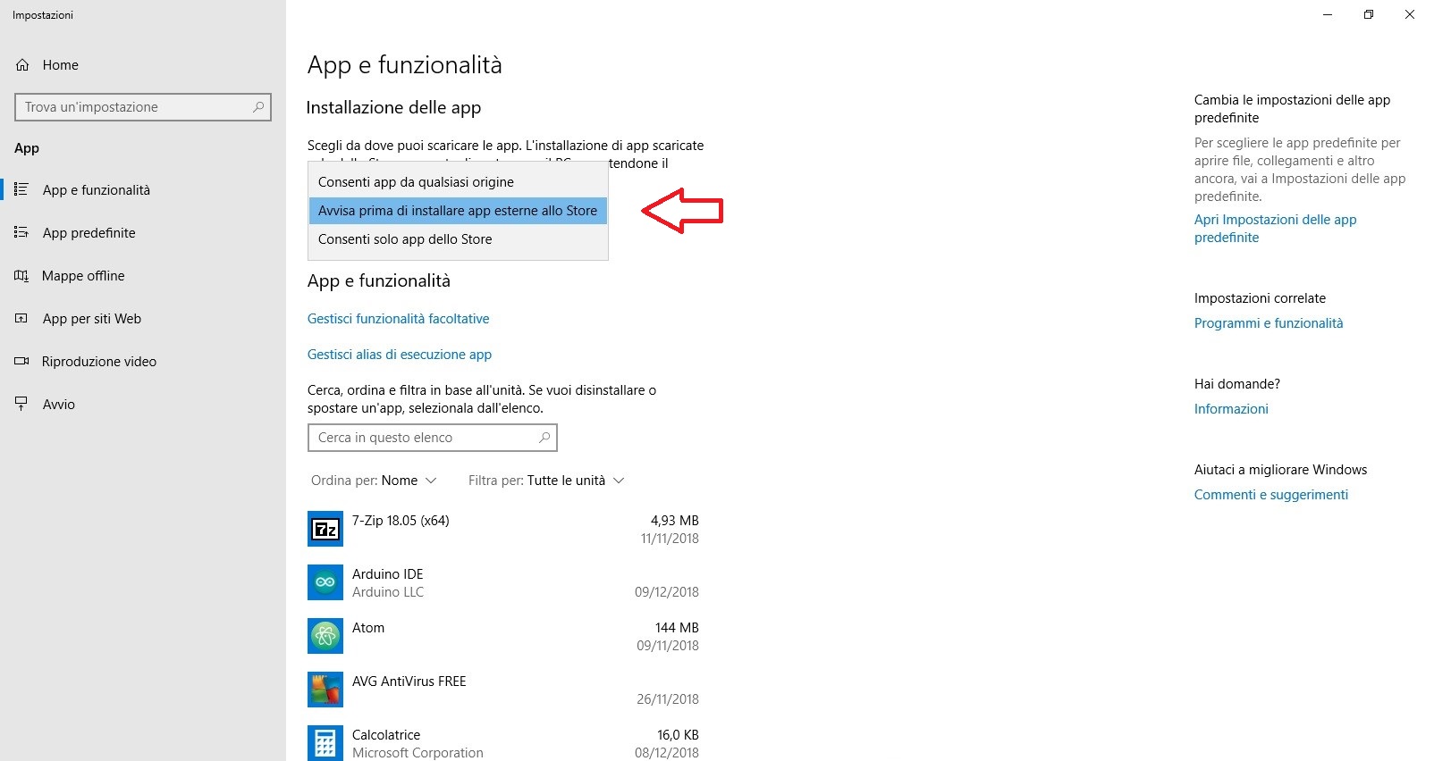
Since the first time I didn't all the programming steps by myself this time I will describe this part for the new programmer (I changed my PC so I had to install the software and drivers again). Meanwhile, to solve the previous problem I had to change a setting of my PC to allow the installation of the necessary programs. So I went in settings ->app and functionality and I selected the option to install external apps from the store.
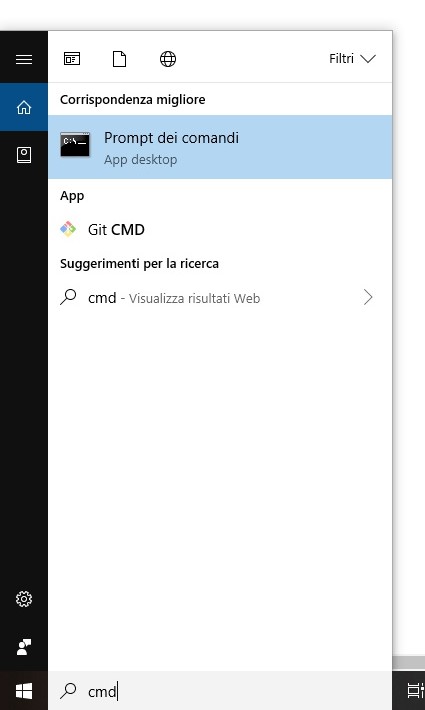
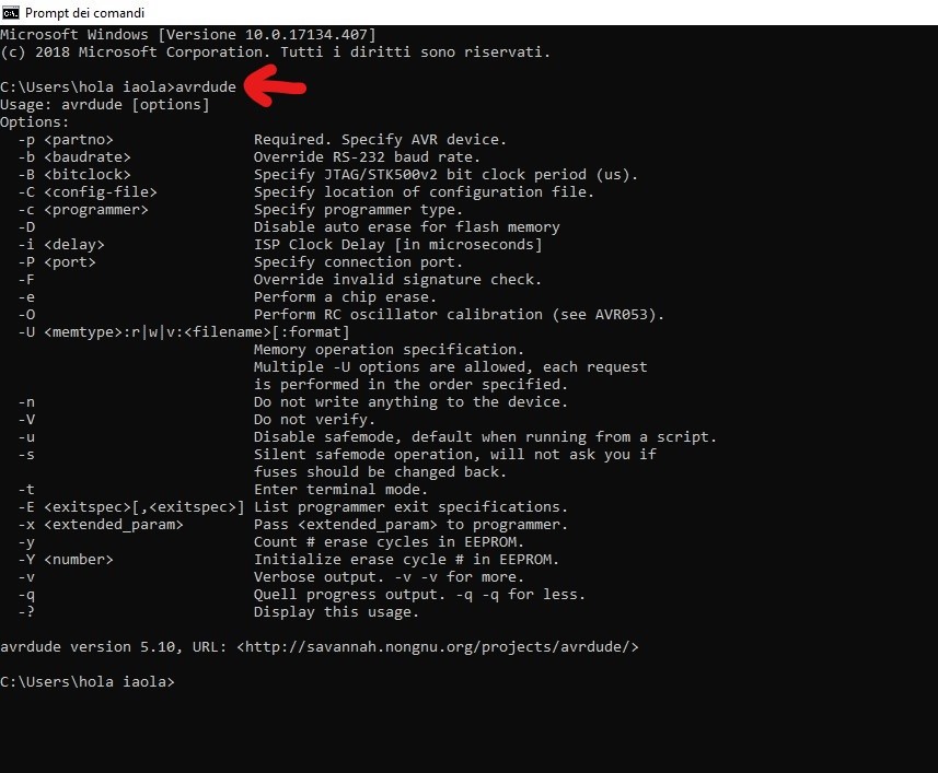
Now I shouldn't have problem installing AVR, so I followed the instructions to install the necessary software (I'm a Windows user). Here the tutorial page. The tutorial to install AVR uses pretty old screenshots, so at first I did not immediately understand how to open the terminal from my pc. So I looked on internet and I saw here how to do it, simply just select the Start button and type cmd.
Then I downloaded and opened the firmware (which was in the tutorial). It's a compressed file so it should be extracted.
The tutorial at some point says:
"The Makefile is in the firmware directory that you downloaded. The Makefile is set up to work with the AVRISP2 by default. If you are using another programmer, you will need to edit the Makefile." And this is my case, so I downloaded notepad++ to modify the makefile.
I followed these steps:
Then type make hex
This command is used to take the source code and it builds the .hex file, that is a format used to store machine low-level code in hexadecimal form.
Then type make fuse: the fuses are some programmable flash memory location that control the chip behaviour and they are related to the microcontroller's clock speed.
then type make program pushes via the ISP the hex and the fuses on the board
After these steps my board is programmed correctly. Surely I will have to learn deeper the aspects of programming, but these steps were the right start.

After downloading the images I have followed the following steps in order to create the files that Roland will run.
First I opened a new fabmodule and went on Programs ->Open server program-> Machines->Roland->mill->SRM-20->PCB. Then I deleted the part circled in red.
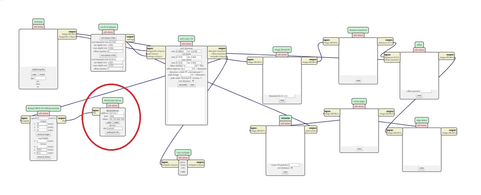
Than Modules - Open server module - File (save).
I connected the new "File - save" module. Than I open my .png traces file clicking on select png file. In the second module I selected mill traces 1/64 (the size of the tip to make traces).
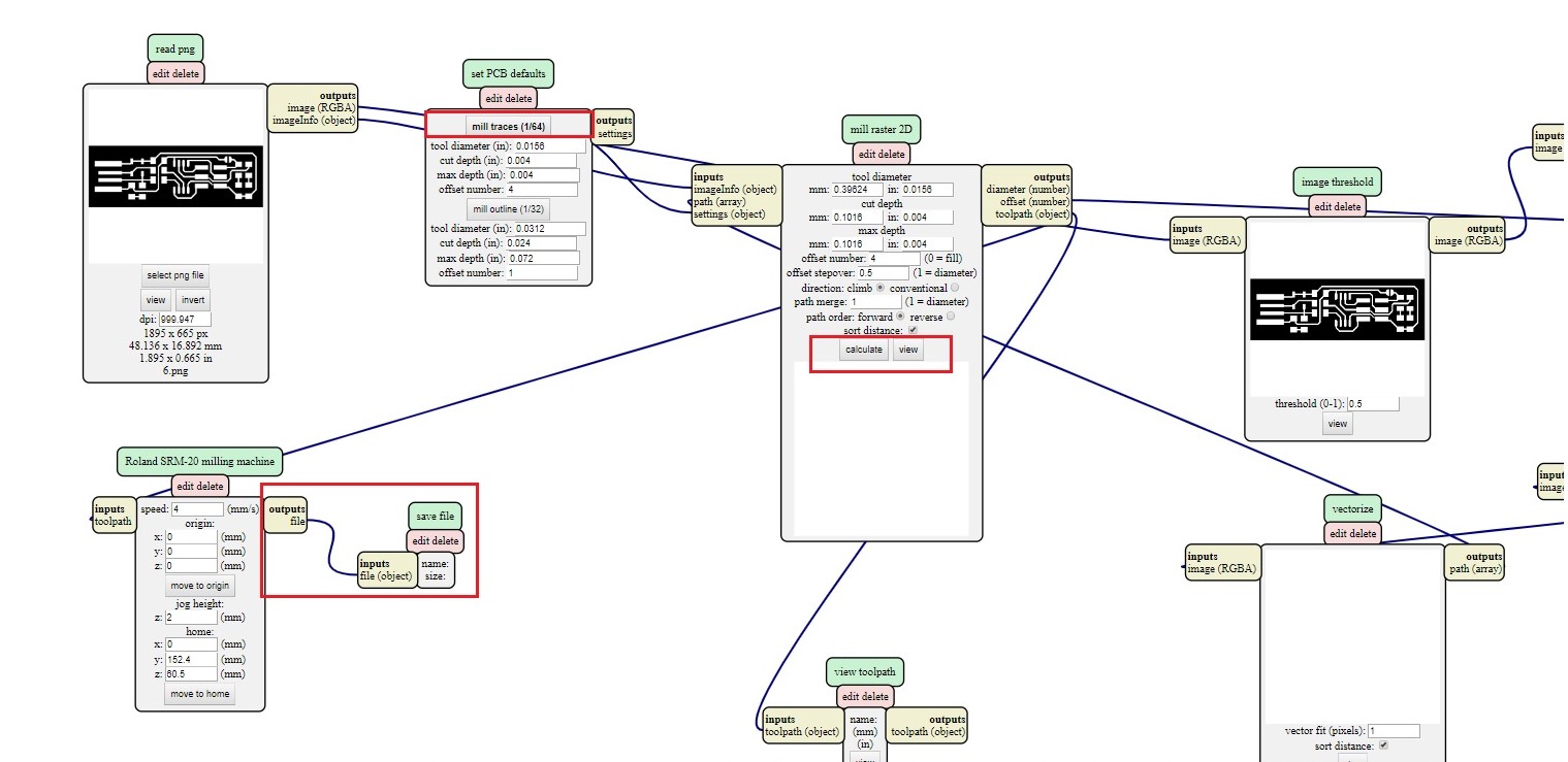
It is important to set all origins to 0.
when all the parameters have been set correctly, just click on calculate and the program will automatically save the file. After the file for the tracks has been saved you have to make the cut file: then load the png file and this time choose the mill outline option
then I took the files and moved them to the PC connected to the Roland
Milling the PCB
In out lab we have the Roland SRM-20
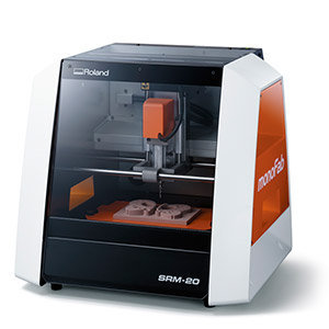
In the lab we have a roland SRM-20. To create the tracks you have to use a very fine (1/64 of) and be very careful because if it falls may break. Once inserted the tip, you have to stick firmly the PCB so it will not move during the cut. Through the program of the machine you can set the origins and give the cut command.
As you can see this is the panel to control our Roland and the instructions. The image is from Flavio Lampus's documentation. To start the milling I used the thinner tip, that is the one from 1/64. In this operation it is essential to be very careful not to drop it because the tip is very thin and could break. Once the tip is secured I set the origins via the control panel. For the Z origin it's necessary to do the operation with caution, in fact you have to make it go down very slowly near the base up to a distance of a few millimeters. At this point I unscrewed and placed it on the PCB with a slight downward pressure to prevent it from getting up while holding the support. At this point you have to go on the control panel to enter the Z. Once all the origins are set correctly, just press on cut to select the file that has to be milled.
Once the milling of the traces was over, I cleaned the residues and I repeated the operation to make the external cut, this time using the 1/32 tip. Once this operation was completed, I unplugged my board and washed it to remove any residues that could compromise the soldering.
before soldering I took all the necessary components for the board (BOM)
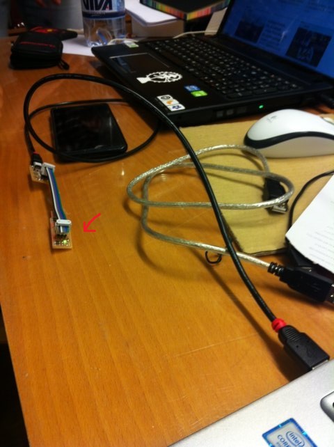
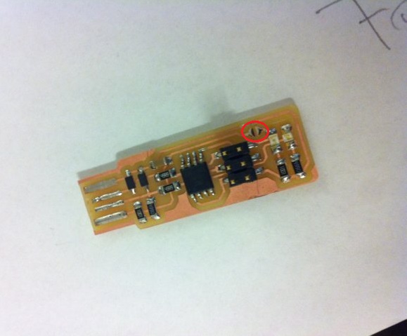
Once I got all the necessary elements and have become familiar with the location and the tools I started to solder. To help myself I took a box found in the laboratory as a support and I fixed the board with patafix to have more stability during welding.
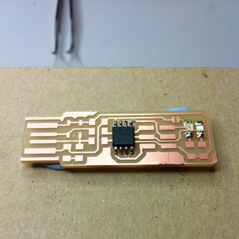
I must say that I had a lot of fun soldering, although at first it was difficult to keep the pieces steady because of their tiny size, and I'm quite satisfied with the result. Another key factor is to be careful not to heat the solder tin too much, otherwise it will not conduct electricity anymore and this would ruin the board.
Programming
The text says: "Windows defender SmartScreen prevented the initiation of an unrecognized app. Running this app could pose a risk to your PC".
So I used the Tommaso Lombardi's PC to program my board, since he did the same board, so the steps were the same.
Run Make Flash
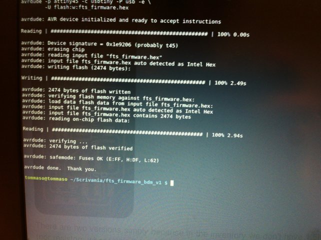
Run Make Fuses

Luckily everything went fine and the programmer was succesfully programmed.
this is the test to check the fabISP
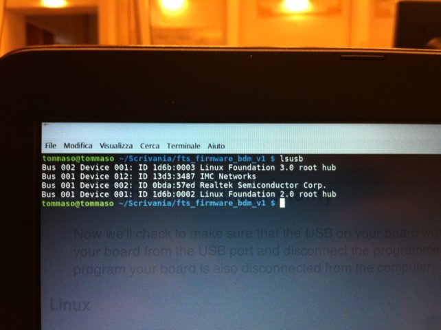
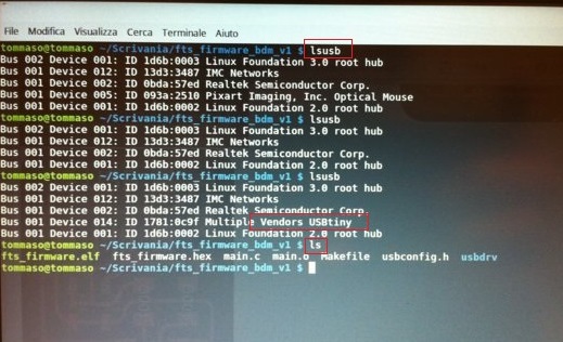
the tutorial recommends to remove the solder from the jumper so is not possible to reprogram the board
Update 05/05/2018
Unfortunately my programmer broke down, so I created a new one. This time I did the FabOptimus.
Since the first time I didn't all the programming steps by myself this time I will describe this part for the new programmer (I changed my PC so I had to install the software and drivers again). Meanwhile, to solve the previous problem I had to change a setting of my PC to allow the installation of the necessary programs. So I went in settings ->app and functionality and I selected the option to install external apps from the store.
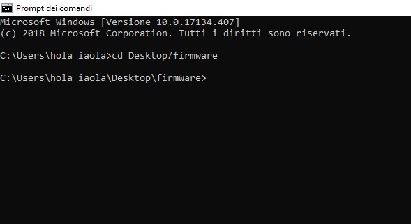
Now I shouldn't have problem installing AVR, so I followed the instructions to install the necessary software (I'm a Windows user). Here the tutorial page. The tutorial to install AVR uses pretty old screenshots, so at first I did not immediately understand how to open the terminal from my pc. So I looked on internet and I saw here how to do it, simply just select the Start button and type cmd.
Then I downloaded and opened the firmware (which was in the tutorial). It's a compressed file so it should be extracted.
The tutorial at some point says:
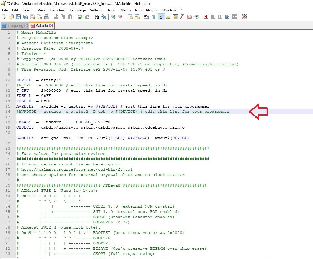
"The Makefile is in the firmware directory that you downloaded. The Makefile is set up to work with the AVRISP2 by default. If you are using another programmer, you will need to edit the Makefile." And this is my case, so I downloaded notepad++ to modify the makefile.
I followed these steps:
- Remove the "#" in front of the line with "usbtiny" in it
- Add a "#" to beginning the line with the "avrisp2" in it to comment it out.
- Save the Makefile
   rm -f main.hex main.lst main.obj main.cof main.list main.map
main.eep.hexmain.elf *.ousbdrv/*.o main.s usbdrv/oddebug.s usbdrv/usbdrv.s
Then type make hex
This command is used to take the source code and it builds the .hex file, that is a format used to store machine low-level code in hexadecimal form.
Then type make fuse: the fuses are some programmable flash memory location that control the chip behaviour and they are related to the microcontroller's clock speed.
then type make program pushes via the ISP the hex and the fuses on the board
After these steps my board is programmed correctly. Surely I will have to learn deeper the aspects of programming, but these steps were the right start.