Week 10: Input devices
Group assignment: measure the analog levels and digital signals in an input device
Individual assignment: measure something (add a sensor to a microcontroller board that you have designed and read it)
Individual assignment: measure something (add a sensor to a microcontroller board that you have designed and read it)
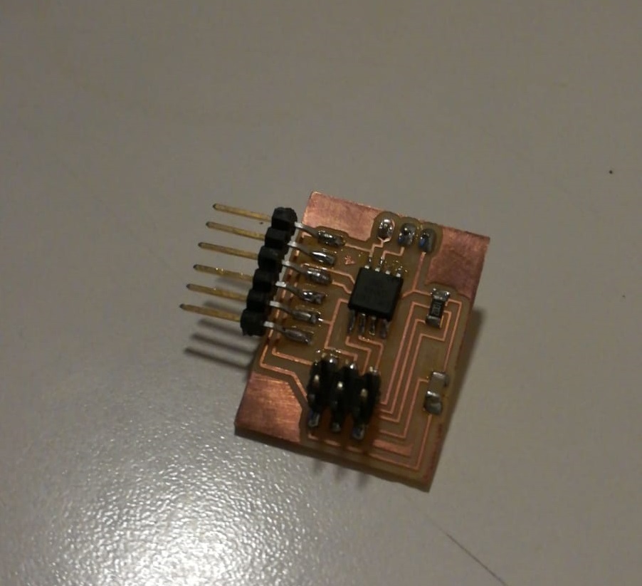
This week I wanted to create a board for the motion sensor (pir) because I think it could be useful for my final project, so I did some research
to understand how to make the circuit.
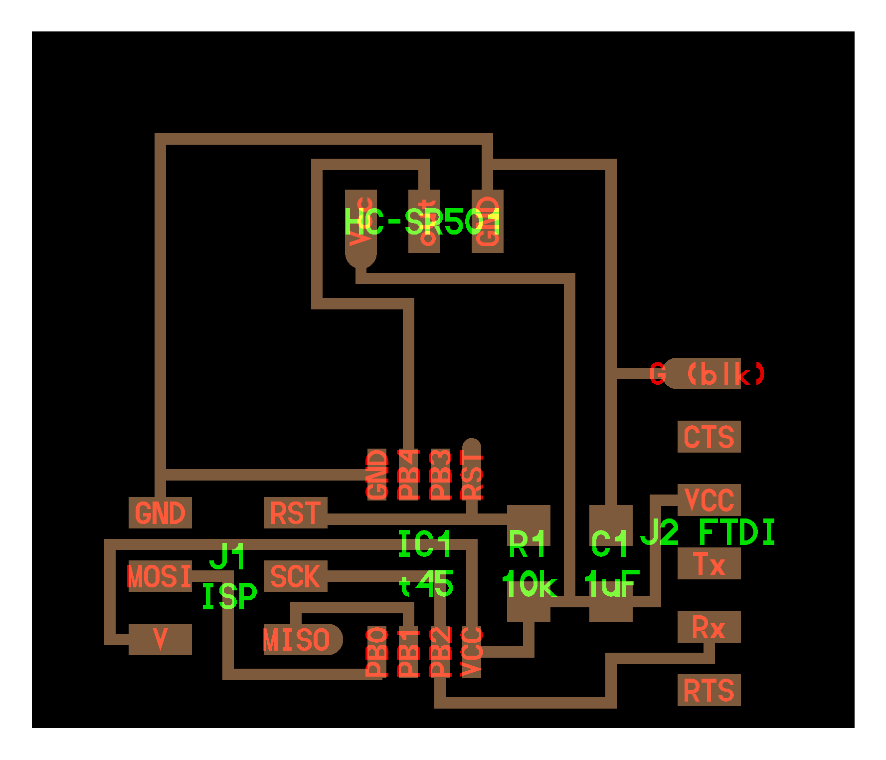
The board
I started looking at the documentation of last years where someone
like me used a PIR sensor and I found this page
very interesting because I discovered which component I had to use:
- ATtiny 45
- 10k resistor
- 1uF capacitor
- 6x1 pinheader
- 3x2 pinheader
- 3x1 female pinheader
Also, I looked at Neil's sample board
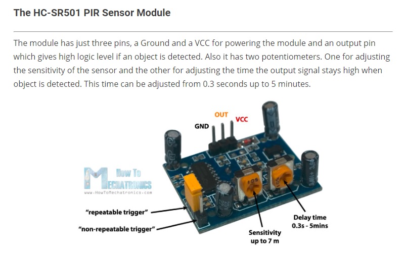
where I saw how to link the various pin, where I noticed at the top the part where connect the PIR sensor. So I wanted to understand better how my sensor works
and I found some information on this page,
where you can see which pin are VCC, OUTPUT, and GND.
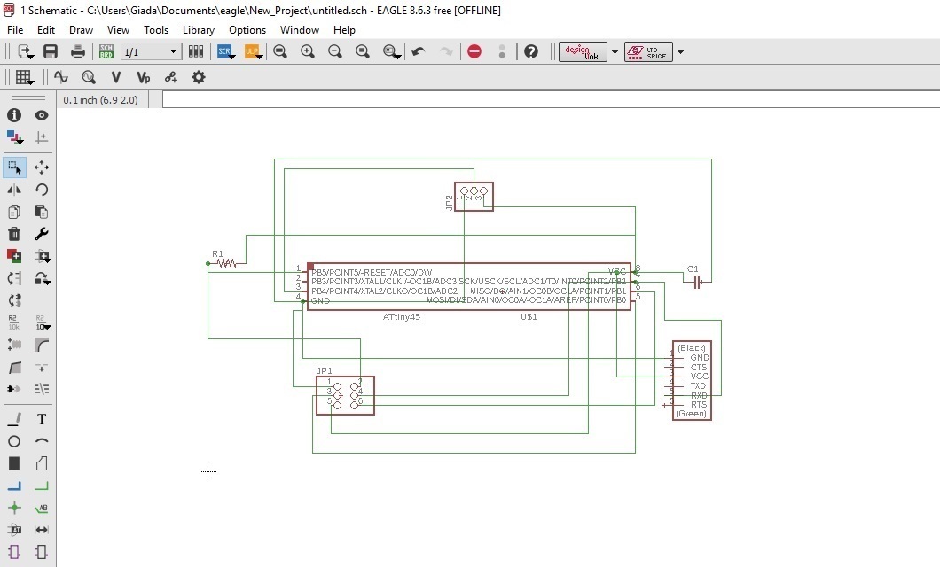
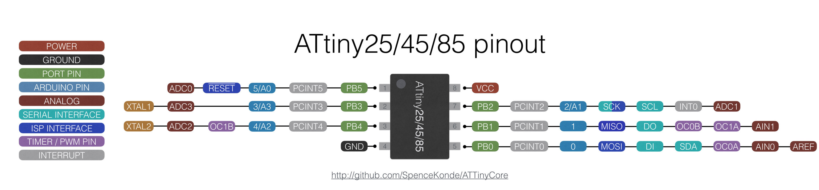
In the Neil's board the output pin of the PIR sensor is linked to the PB4 of the Attiny 45, so I looked to the datasheet to understand better why and I saw this section.
According to the datasheet the pin 3 (PB4) is the output and the sensor has to be connected to an ADC port (Analog to digital converter). Also the PB2 is connected to the serial pin because this is the RX in serial communication. Now I can start to make my board with the steps that I learned in week 6
In the Neil's board the output pin of the PIR sensor is linked to the PB4 of the Attiny 45, so I looked to the datasheet to understand better why and I saw this section.
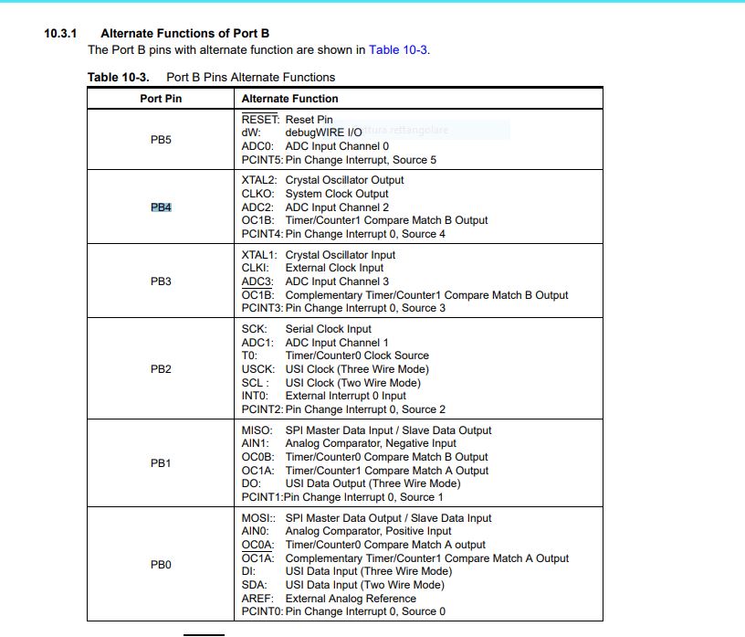
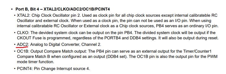
According to the datasheet the pin 3 (PB4) is the output and the sensor has to be connected to an ADC port (Analog to digital converter). Also the PB2 is connected to the serial pin because this is the RX in serial communication. Now I can start to make my board with the steps that I learned in week 6
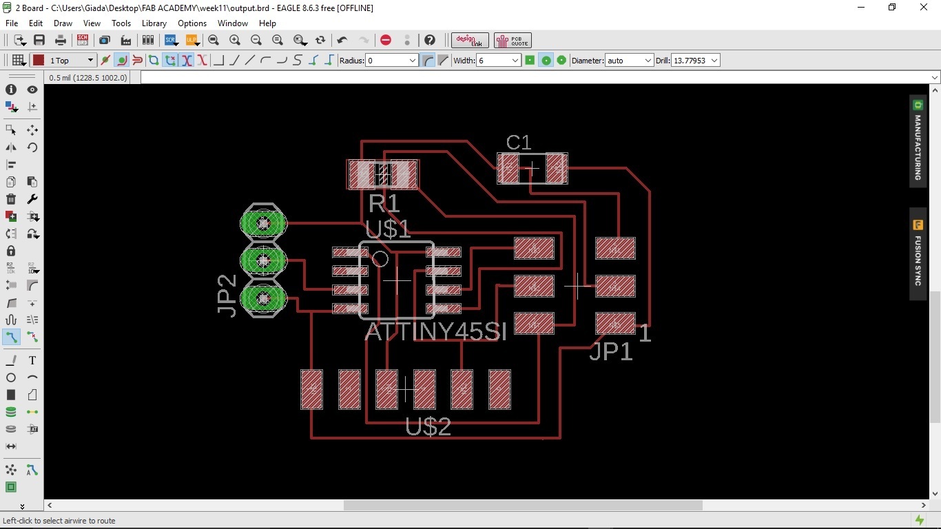
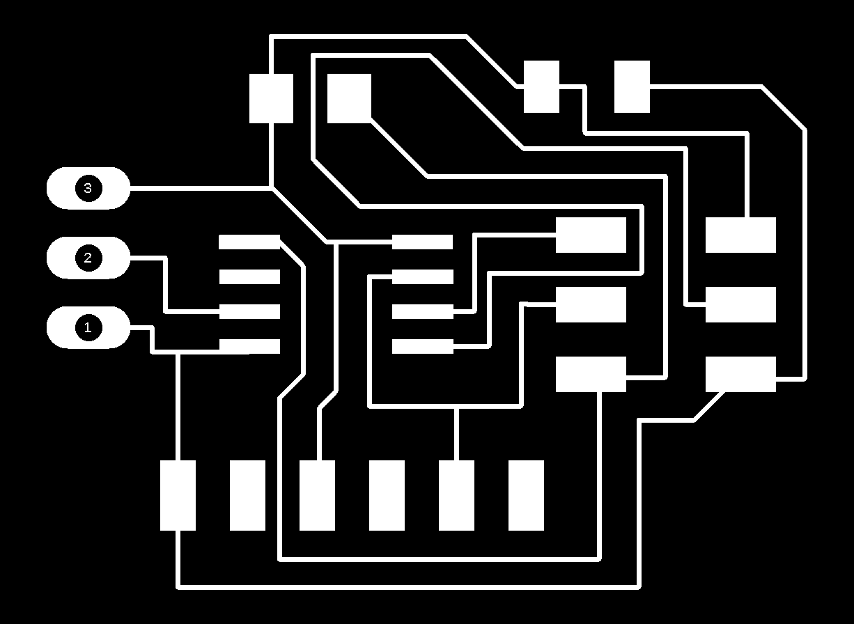
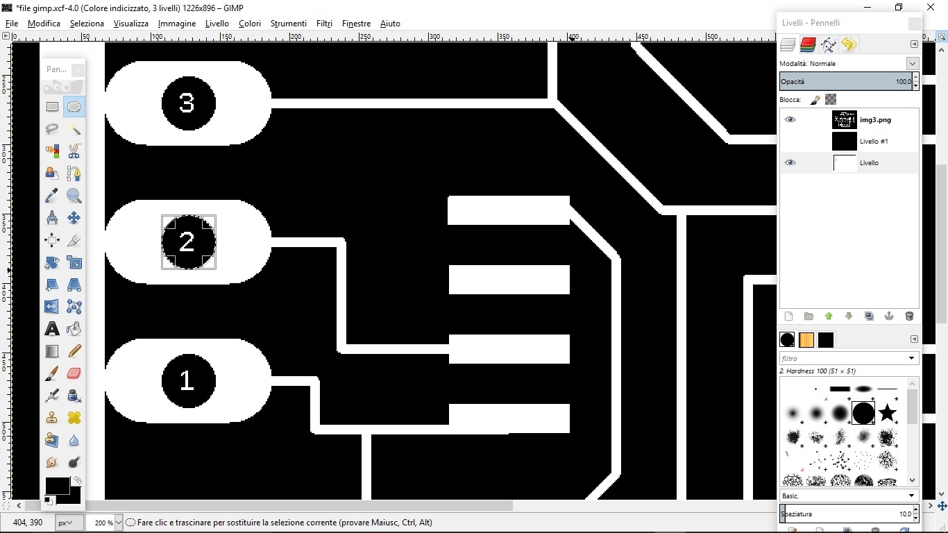
This time my board has 3 holes and I had to learn how to create holes on Gimp, so
I followed this tutorial. To make sure that the holes were aligned and in the right place, I selected
the level of the outline with the traces level visible, then I applied the method suggested by the tutorial: I created a round selection, I set the thickness
of that and finally I filled it with the appropriate tool
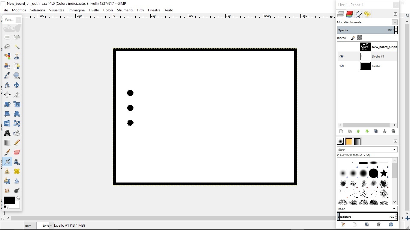
After saving the image and carrying out the steps on the fabmodules (see week 4) I milled and soldered the board.
Programming with Arduino
Now it's program time. Conceptually I have to program the board in order to send the data
of the motion sensor and print them on the serial monitor.
Honestly, I took a sketch already done (in the prevoius documentation)
and tried to understand the parts thanks also to the Arduino site.
Next, to the individual functions, I explained what they do.
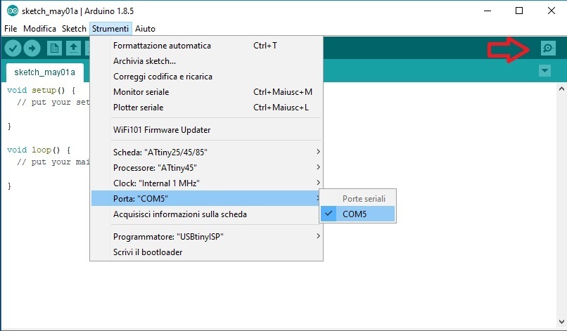
Using Arduino IDE to program it's necessary to know the corresponding wording of our microcontroller, in this case
my pin 3 of the ATtiny45 corresponds to pin 4/A2 on Arduino.
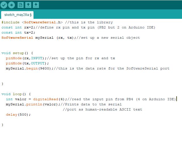
I used the SoftwareSerial library which is already in Arduino IDE. The variables must be defined before the instructions. Basically this sketch works like this: in the setup phase I inserted the instructions that the program will do at the beginning. With pinMODE I have defined the type of digital port, if it must be an output or an input. Serial.begin initializes the serial monitor in order to read the data(9600 baudrate, indicates the number of transitions per second). Using the digitalRead() function we will read the output of the sensor and if its high or if an object is detected it will activate the relay. With mySerial.println (valor) we tell the program to show us the real value. The delay tells how long it takes to execute the function before starting another one or repeating the one before, in this case the time is half a second.
This is my sketch
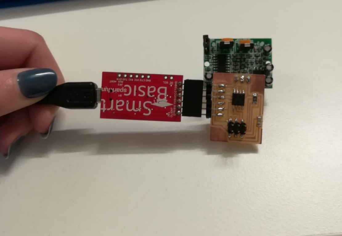
After that I loaded the program on the board, taking care to position the FTDI cable in the correct way
I used the SoftwareSerial library which is already in Arduino IDE. The variables must be defined before the instructions. Basically this sketch works like this: in the setup phase I inserted the instructions that the program will do at the beginning. With pinMODE I have defined the type of digital port, if it must be an output or an input. Serial.begin initializes the serial monitor in order to read the data(9600 baudrate, indicates the number of transitions per second). Using the digitalRead() function we will read the output of the sensor and if its high or if an object is detected it will activate the relay. With mySerial.println (valor) we tell the program to show us the real value. The delay tells how long it takes to execute the function before starting another one or repeating the one before, in this case the time is half a second.
This is my sketch
After that I loaded the program on the board, taking care to position the FTDI cable in the correct way
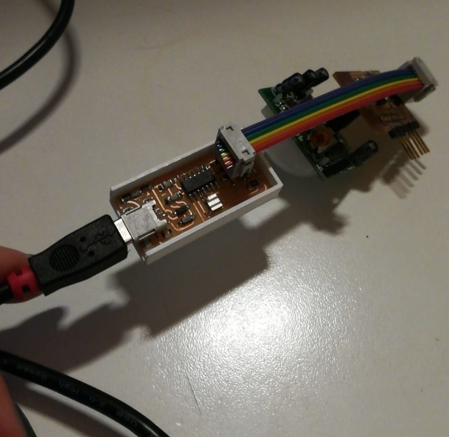
Then I connected the board to the ftdi cable.
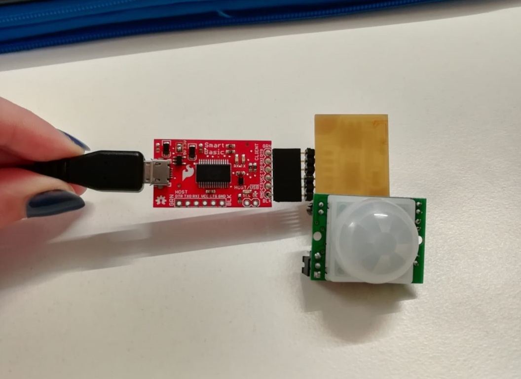
On Arduino IDE, I selected the port from which to read the data of the motion sensor and I opened
the serial monitor.
The result
How you can see when the PIR detect some movement the serial monitor
prints 1, otherwise it prints 0.
prints 1, otherwise it prints 0.
Since I'm going to use the pir in my final project I think I'll look other methods to program it in the future