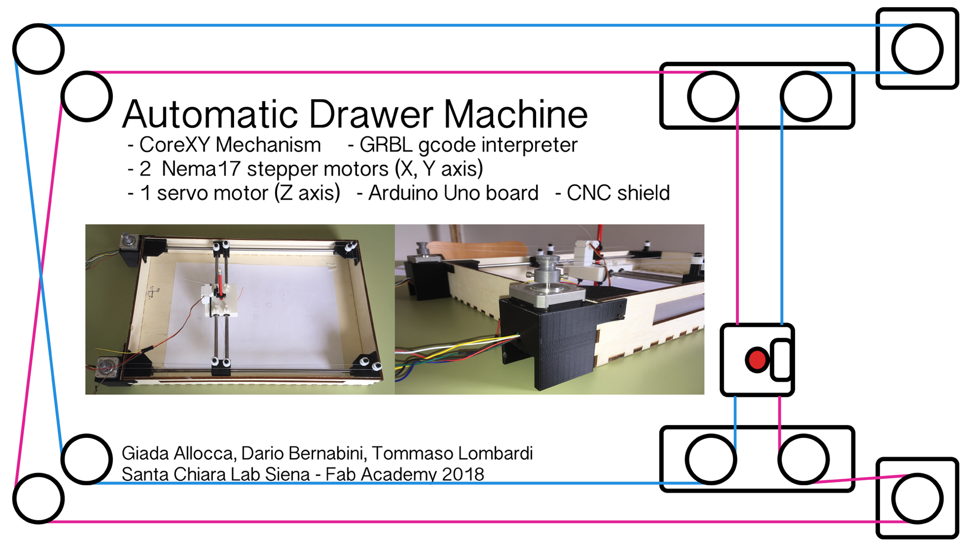
As we said for last weekly assignment, our plans are to use these hardware to move our CoreXY drawing machine:
1x Arduino Uno
1x CNC Shield
2x Pololu drivers
2x Nema17 stepper motors
1x servo motor
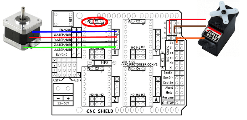
After connected the CNC Shield on the Arduino board, we put on it on X section a driver and the stepper motor using this layout, paying attention to connect properly the driver hardware (we took as reference point the ENABLE pin on upper-left corner):
In order to work with the Arduino CNC Shield and to to interpret the GCODE we use GRBL software.
A complete list of GRBL commands is available Here.
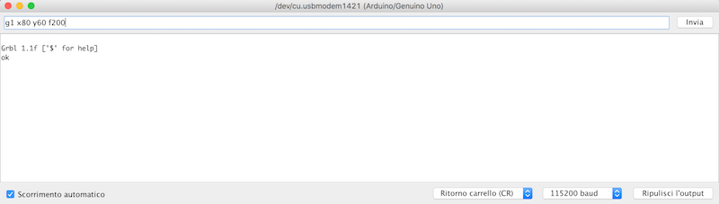
Using one of them we tried to communicate with the board using the simple command g1 x10 y10 f200 and the result was "ok", so GRBL was properly uploaded and ready to use. The command means:G1 - it's for motion mode. Means "go to coordinate X, Y... at speed F that I will tell you"
X10 - point 10 on X axis
Y10 - point 10 on Y axis
F200 - it's the feed rate
After that we searching online something could be useful for us to control a servo motor via GRBL. We found a good solution inside This Tutorial: basically it explain how to move two stepper motors for X and Y axis and use a servo for the Z. But it asks to modify GRBL software to be flashed again on Arduino board.
The first condition is to use a modified version of spindle_control.c available Here to be copied inside the GRBL replacing the original one in the folder in Arduino IDE example folder.This allows us to control the servo motor via gcode.The second is to modify the config.h file at line 189, uncommenting
Than we open again Arduino IDE and upload again GRBL using grblUpload sketch with these new changes.
--> Download modified config.h
--> Download modified spindle_control.c
During this occasion we also setted up steps and max rate for X and Y axis. According with Official GRBL Setting Guide, we launched these commands via serial monitor:
The formula to calculate steps/mm is: steps_per_mm = (steps_per_revolution*microsteps)/mm_per_rev, where:steps_per_revolution = 200
microsteps = 8
mm_per_rev = 10*π
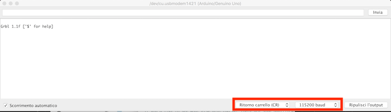
Grbl is a no-compromise, high performance, low cost alternative to parallel-port-based motion control for CNC milling. It will run on a vanilla Arduino (Duemillanove/Uno) as long as it sports an Atmega 328.Flashing it in our Arduino Uno was very simple: we downloaded the source code from Here, we unzipped the folder and we copied the grbl folder inside Arduino IDE's Libraries folder (in Mac OS Arduino app/Contents/Java/libraries). Than we connected our Arduino board and we upload the example sketch named grblUpload. Than we opened the Arduino Serial Monitor and, after setting up Return cart and 115200 baud rate this is the result:
A complete list of GRBL commands is available Here.
Using one of them we tried to communicate with the board using the simple command g1 x10 y10 f200 and the result was "ok", so GRBL was properly uploaded and ready to use. The command means:
After that we searching online something could be useful for us to control a servo motor via GRBL. We found a good solution inside This Tutorial: basically it explain how to move two stepper motors for X and Y axis and use a servo for the Z. But it asks to modify GRBL software to be flashed again on Arduino board.
The first condition is to use a modified version of spindle_control.c available Here to be copied inside the GRBL replacing the original one in the folder in Arduino IDE example folder.This allows us to control the servo motor via gcode.The second is to modify the config.h file at line 189, uncommenting
#define COREXY;. We are saying "Hey, GRBL, I want to work with a CoreXY mechanism!"
Than we open again Arduino IDE and upload again GRBL using grblUpload sketch with these new changes.
--> Download modified config.h
--> Download modified spindle_control.c
During this occasion we also setted up steps and max rate for X and Y axis. According with Official GRBL Setting Guide, we launched these commands via serial monitor:
$100=51 --> X steps/mm
$101=51 --> Y steps/mm
$110=600 --> X max rate, mm/min
$111=600 --> Y max rate, mm/min
The formula to calculate steps/mm is: steps_per_mm = (steps_per_revolution*microsteps)/mm_per_rev, where:
In our first test we connect a stepper motor to the CNC shield's X axis with a driver in order to test if everythings works fine. We also connected the shield to 12V and the Arduino to a PC. To initially test them we used Universal GCODE Sender, a very nice and powerful Java software that allows to interface with a CNC controller such as GRBL we used. In the video below you can see out very first try, moving stepper motor on X+ direction:
In our second try we insert the second stepper motor and we test again with GCODE Sender:
Finally we tested also the 5v servo motor for Z axis. Initially we had some problem to control it via serial port using Universal GCODE Sender because it send the command "Z..." to move up and down. But these kind of commands are good for stepper motor. Using a servo, we had to change command to send: Z axis could be moved up and down using M3 S200 and M5 S200. The rotation angle is given by the parameters inserted inside the spindle_control.c file at lines 48 and 49 with
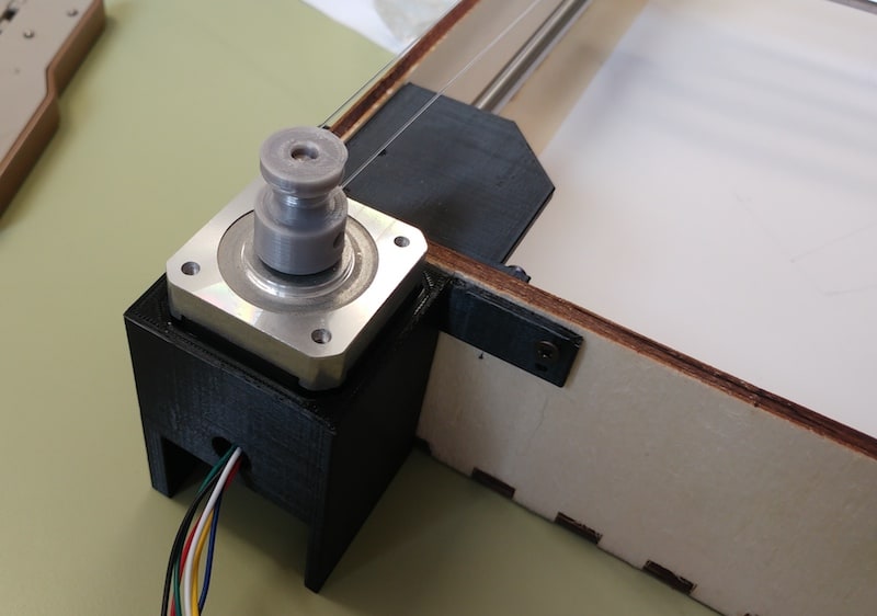
After that we made some support to keep the stepper fixed in the same position and we settled around our machine's frame.
After that we tested again our machine using UGS with some free movements and we manually wrote a simple GCODE file for drawing a square in three passes.
In our second try we insert the second stepper motor and we test again with GCODE Sender:
Finally we tested also the 5v servo motor for Z axis. Initially we had some problem to control it via serial port using Universal GCODE Sender because it send the command "Z..." to move up and down. But these kind of commands are good for stepper motor. Using a servo, we had to change command to send: Z axis could be moved up and down using M3 S200 and M5 S200. The rotation angle is given by the parameters inserted inside the spindle_control.c file at lines 48 and 49 with
#define PEN_SERVO_DOWN and #define PEN_SERVO_UP. We decided for a delta=2 (SERVO_DOWN=16 and SERVO_UP=18) because basically we need only a small movement to not overstretch the servo, but to still allow the tip not to touch the paper sheet. Thanks to modifications we made, we succesfully control the servo motor for the Z axis.
After that we made some support to keep the stepper fixed in the same position and we settled around our machine's frame.
After that we tested again our machine using UGS with some free movements and we manually wrote a simple GCODE file for drawing a square in three passes.
For the final test, we manually wrote a simple GCODE file that draws three 10mm squares in three different positions. Of course we used M3 and M5 commands to reproduce movements for Z axis.
Saving it as a .ngc file, we could open and send it via Universal GCODE Sender to our machine. The final video of our result it's at the top of this page.
--> Download GCODE_TEST.ngc
We fixed it by configurating correctly some values of GRBL.In particular the $100,$101 parameters. Here is the official description :
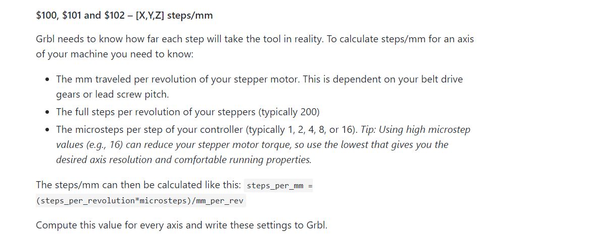
For the last Formula is useful to know that we used 2 Nema17 Stepper motor that needs 200 steps per revolution.We setted the microsteps per step by 8 so the last variables to know was mm_per_rev.To find the mm per revolution was enough to use the formula for the circumference length 2*Pi*Radius,where the Radius is the radius of the pulley we designed(5mm in our case).
Once we found the correct values we setted them by serial comunication using UGS and the reasults were pretty satisfying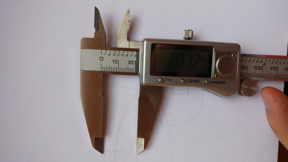
Saving it as a .ngc file, we could open and send it via Universal GCODE Sender to our machine. The final video of our result it's at the top of this page.
--> Download GCODE_TEST.ngc
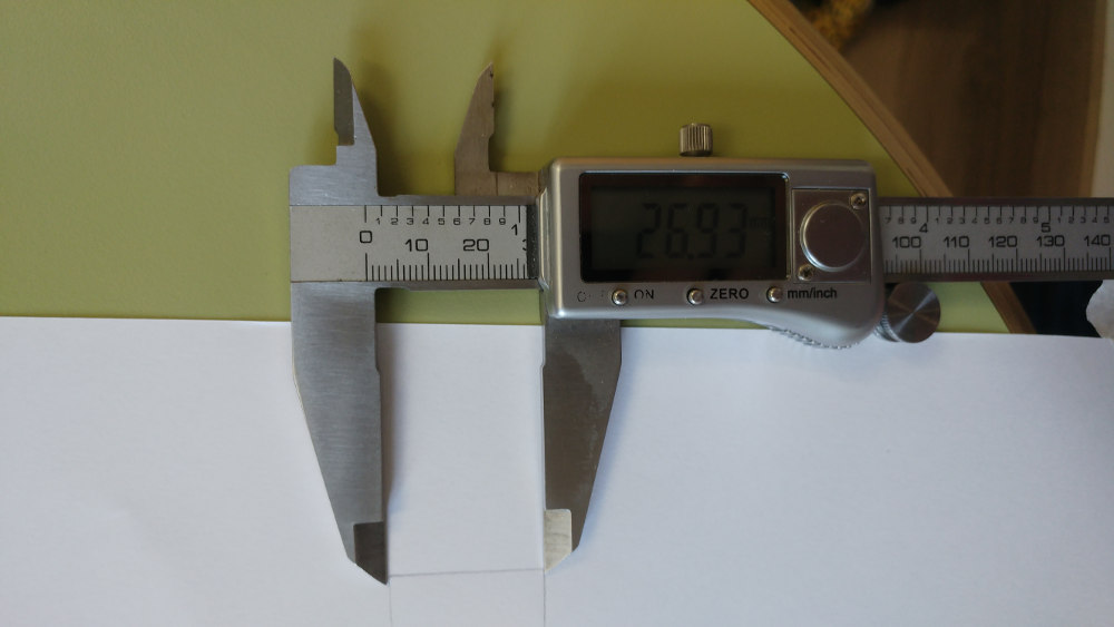
Some Problems
We draw a 2cm square to test if the measure we wanted were respected. The lenght of each side of the square were wrong :We fixed it by configurating correctly some values of GRBL.In particular the $100,$101 parameters. Here is the official description :
For the last Formula is useful to know that we used 2 Nema17 Stepper motor that needs 200 steps per revolution.We setted the microsteps per step by 8 so the last variables to know was mm_per_rev.To find the mm per revolution was enough to use the formula for the circumference length 2*Pi*Radius,where the Radius is the radius of the pulley we designed(5mm in our case).
Once we found the correct values we setted them by serial comunication using UGS and the reasults were pretty satisfying
Plans for future improvements are to apply some modifications to the machine: