Design a machine that includes mechanism+actuation+automation and build the mechanical parts and operate it manually
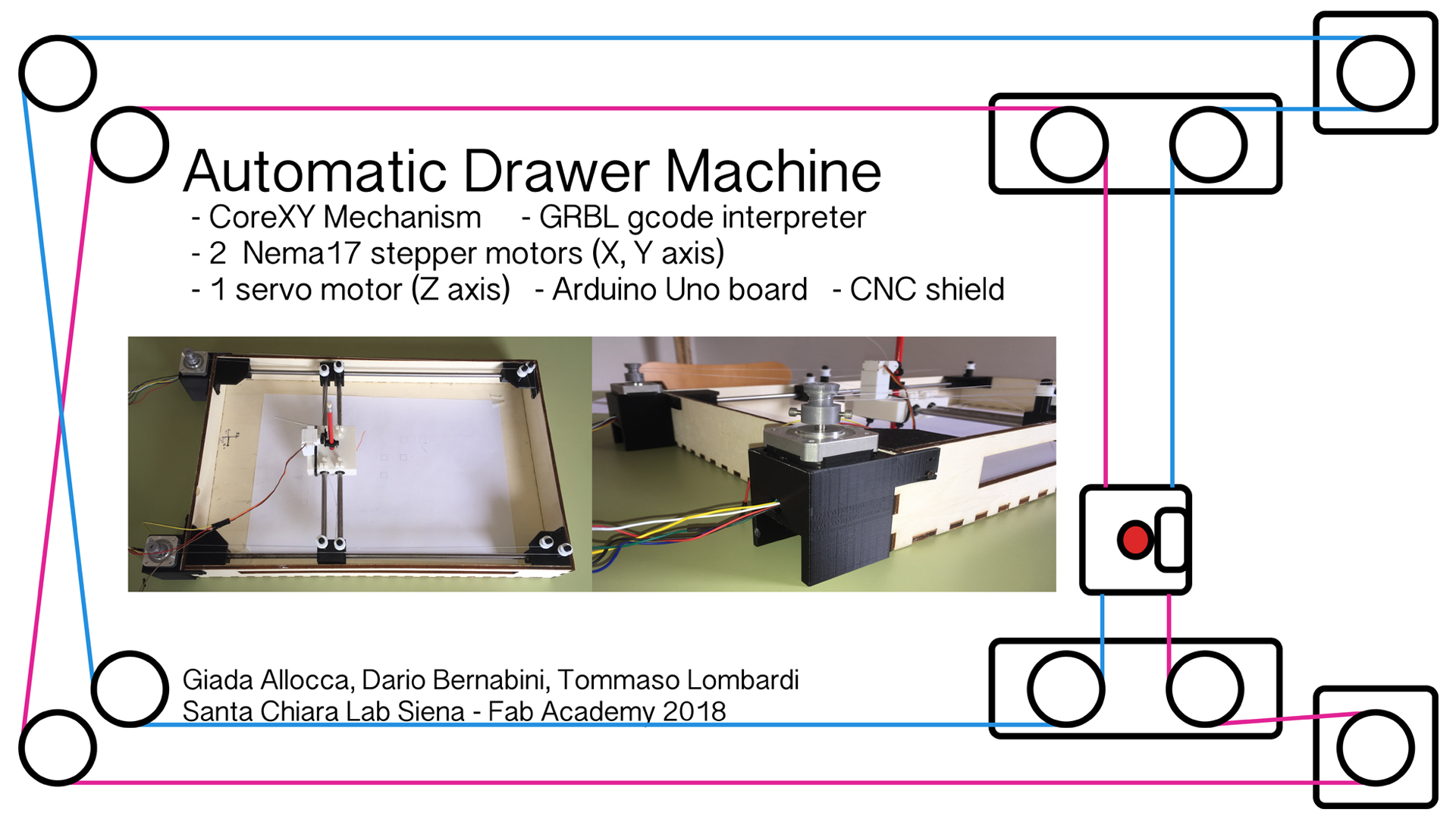
The purpose for this weekly assignment is to create an automatic drawing machine using the CoreXY mechanism. We take ispiration founding on YouTube two interesting videos that show two CoreXY machines, one passive moved manually and the other one automatic that is able to draw a simple figure with a pen.
We choosed this kind of mechanism because we found it very amazing and flexible to create. The theory behind a CoreXY machine is available at This Link.
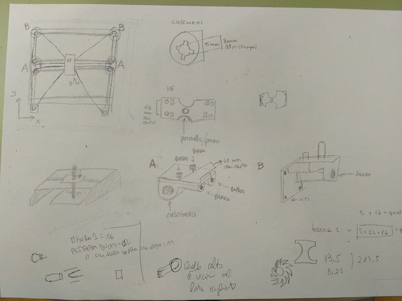
As first step we draw a simple sketch on a paper to make it clearer what to do.
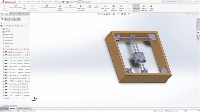
Than, starting from this drawing, we realize a 3D assembly on SolidWorks: in this way we had a concrete view of our idea.
We choosed this kind of mechanism because we found it very amazing and flexible to create. The theory behind a CoreXY machine is available at This Link.
As first step we draw a simple sketch on a paper to make it clearer what to do.
Than, starting from this drawing, we realize a 3D assembly on SolidWorks: in this way we had a concrete view of our idea.
In order to assemble properly the entire machine as we want we needed to design and create some 3D objects. In particular we created:
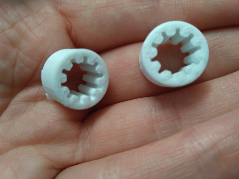
Linear Bearings - See on SketchFab - Download
Pulleys - See on SketchFab - Download
Lateral Holders - See on SketchFab - Download
Central Holder - See on SketchFab - Download
Angular Holder #1 - See on SketchFab - Download
Angular Holder #2 - See on SketchFab - Download
Angular Holder #3 - See on SketchFab - Download
Angular Holder #4 - See on SketchFab - Download
Cubes - See on SketchFab - Download
Plain Pulleys - See on SketchFab - Download
---> Download All Files (ZIP Archive)
In our first test we connect a stepper motor to the CNC shield's X axis with a driver in order to test if everythings works fine. We also connected the shield to 12V and the Arduino to a PC. To initially test them we used Universal GCODE Sender, a very nice and powerful Java software that allows to interface with a CNC controller such as GRBL we used. In the video below you can see out very first try, moving stepper motor on X+ direction:
In our second try we insert the second stepper motor and we test again with GCODE Sender:
Finally we tested also the 5v servo motor for Z axis. Initially we had some problem to control it via serial port using Universal GCODE Sender because it send the command "Z..." to move up and down. But these kind of commands are good for stepper motor. Using a servo, we had to change command to send: Z axis could be moved up and down using M3 S200 and M5 S200. The rotation angle is given by the parameters inserted inside the spindle_control.c file at lines 48 and 49 with #define PEN_SERVO_DOWN and #define PEN_SERVO_UP. Thanks to modifications we made, we succesfully control the servo motor for the Z axis.
We decided to created the external frame in plywood with our laser cutter because it's cheap, easy to design and fast to be produced. As first thing we obviusly calculated the kerf, that in this case was around 0,1 mm. Than we designed a parametric external frame as a sort of box with a gap in one side to allow to insert easily a paper inside.
-->Download AI
-->Download AI
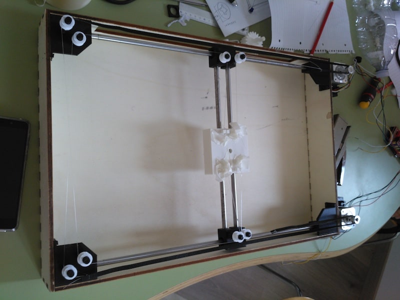
First of all we fixed the bars guides inside the corners of the frame with some screws, then mounted the frame by matching its joints. So we inserted the central piece and inserted the bars in such a way that everything was closed properly. We also oiled the bars so that the mechanism ran out better. Given the momentary lack of straps of the ideal length for our machine, we used those few that we only had for the pulley attached to the stepper and for the rest of the simple fishing nylon. The connection is the same as the figure below:
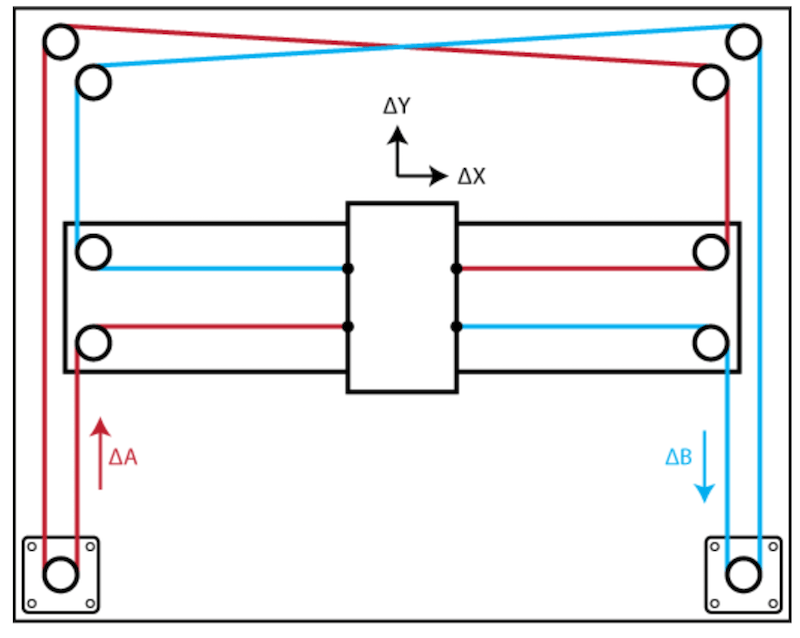
And here is the result after assembling all components:
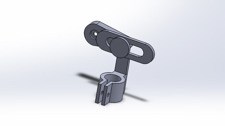
The purpose for next weekly assignment it's obviusly to automate this machine using an Arduino Uno board with a CNC Shield and GRBL as GCODE interpreter. We also need to find a solution for Z axis: infact we think to use a servo motor instead a stepper. We used a scotch yoke mechanism to move the pen on the Z axis and this is the model on Solidworks.
And here is the result after assembling all components:
The purpose for next weekly assignment it's obviusly to automate this machine using an Arduino Uno board with a CNC Shield and GRBL as GCODE interpreter. We also need to find a solution for Z axis: infact we think to use a servo motor instead a stepper. We used a scotch yoke mechanism to move the pen on the Z axis and this is the model on Solidworks.

--> Click Here to go to next weekly assignment "Machine Design"