WEEK 6 - ELECTRONICS DESIGN
SIXTH ASSIGNMENT
- Use the test equipment in your lab to observe the operation of a microcontroller circuit board
- Redraw the echo hello-world board.
- Add (at least) a button and LED (with current-limiting resistor).
- Check the design rules, make it, and test it.
- Extra credit: simulate its operation.
- Extra credit: render it.
Group assignment:
Individual assignment:
This week was difficult, we learned about components use to create boards (resistors, capacitors, LEDS, etc), some basic principles of how a PCB works (VCC, Ground, current flow, etc) and different ways to design circuits with a software named Eagle.
USE THE TEST EQUIPMENT IN YOUR LAB TO OBSERVE THE OPERATION OF A MICROCONTROLLER CIRCUIT BOARD
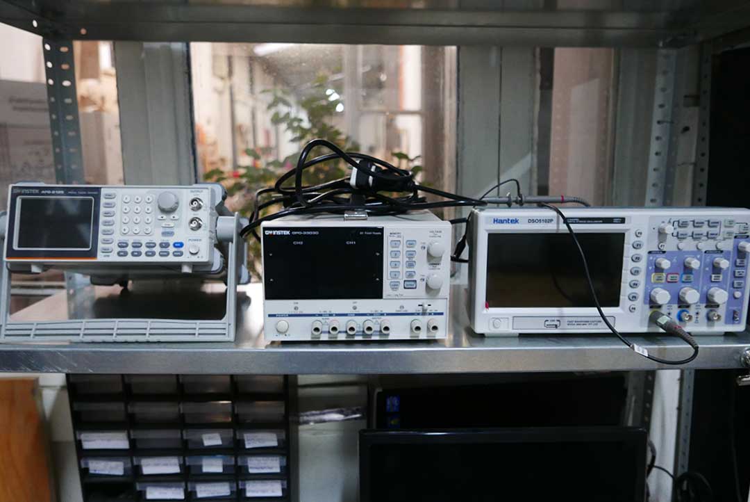
For this assignment we learned and practice with the equipment in our Fab Lab that helps us to measure our electronics circuits. For example:
REDRAW THE ECHO HELLO-WORLD BOARD
For this week´s assignment we had to redraw the Echo Hello_World board that Neil provided us with.
My instructor suggested me to use the softwareEagle because of it´s great user-friendly interphase and also because since it´s an Autodesk program, it has some compatibility with other softwares.
After installing Eagle I began a new Project/Schematic and downloaded the Fab Library that contains most the components used for the Fab Academy boards, after I downloaded I added it to the Eagle Library folder.
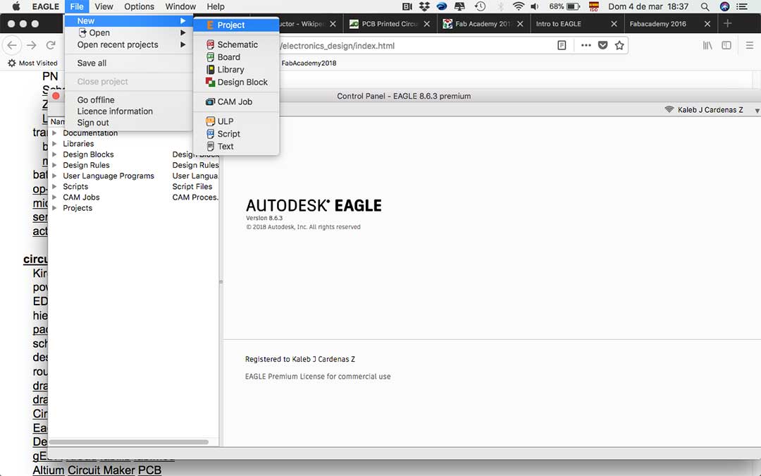
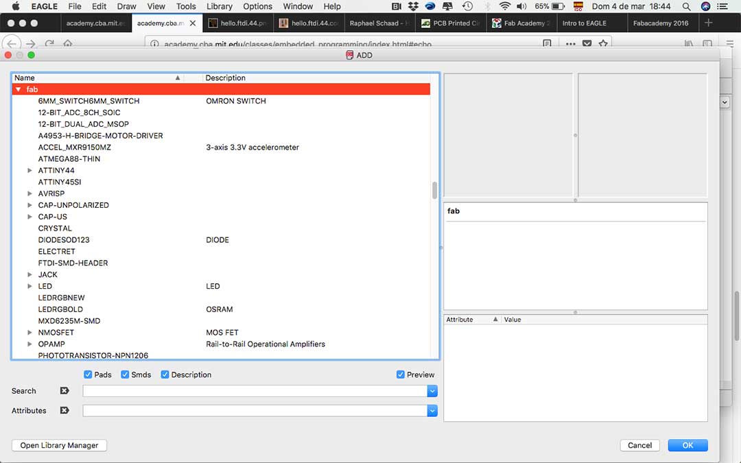
Then it was time to explore the software in order to understand how it works, our instructor mentioned some of the tools in Eagles schematic. Then I imported the schematic from the Fab library and star adding all the components for my board.
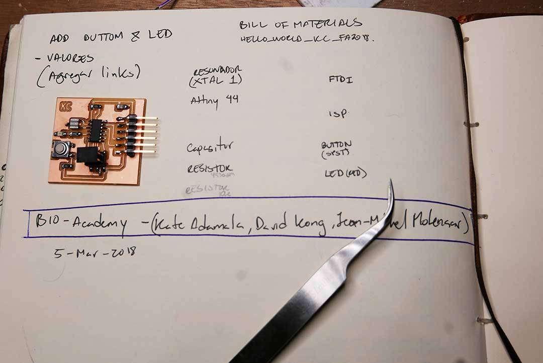
This is the bill of materials used for the Echo Hello-World board:
The commands I used to start putting my schematic together were the following:
You have to be very careful with the connections you make on the schematic, also it is important to double check the values you give to your components like the Resistor, Capacitor and Cristal (Resonator).

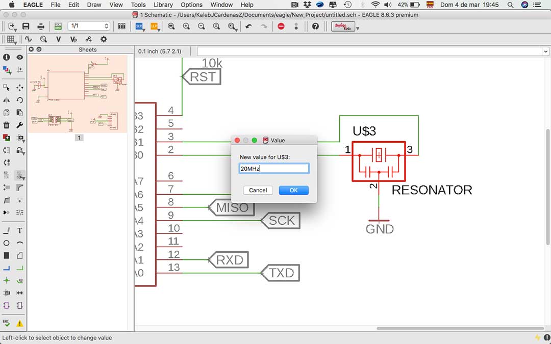
Then it was time to change to the board with the following command: Menu – File – Switch to board
All your components will appear disorganized you must place them in order to star designing your board. You can also use a command named grid to help you make your traces more accurate.
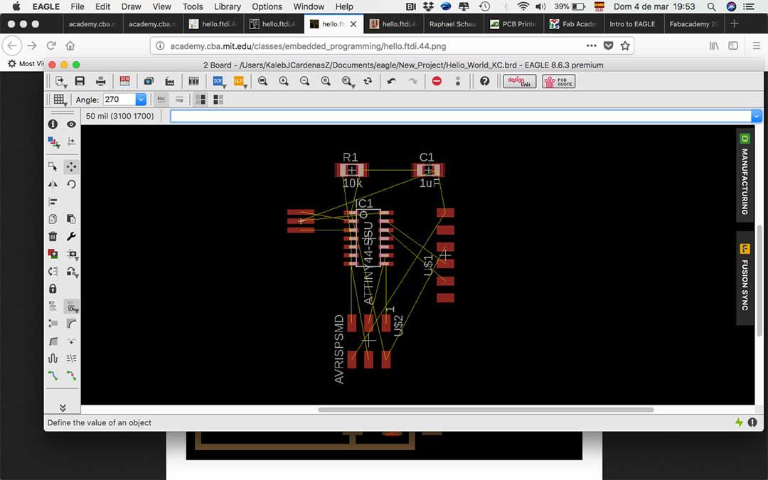
Then it was time to add the new components.
ADD (AT LEAST) A BUTTON AND LED (WITH CURRENT-LIMITING RESISTOR
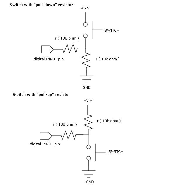
I first checked which LED, button and resistors I could use for my new components on the board. I had to do some research and came to the conclusion that a pull down button (see image below) was much better because when it´s not in use it keeps the VCC (energy) turned down. Since it’s connected to the ground, it keeps the circuit closed. Then I did some research on which resistor to use with a link from Sparkfun
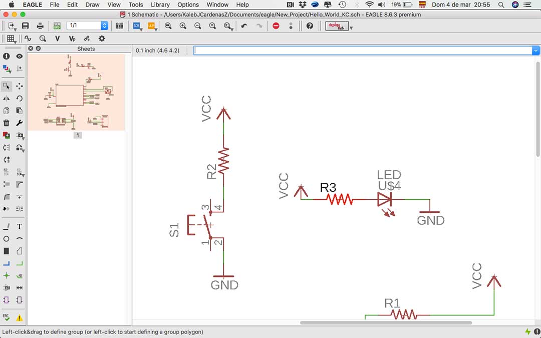
Then it was time to add the LED and its resistor as well. I had to calculate the value of resistance and I saw that I needed 680 Ohms, I decided to use 499 Ohms resistor, which is the one we have in our Fab Lab.
CHECK THE DESIGN RULES, MAKE IT AND TEST IT
Check
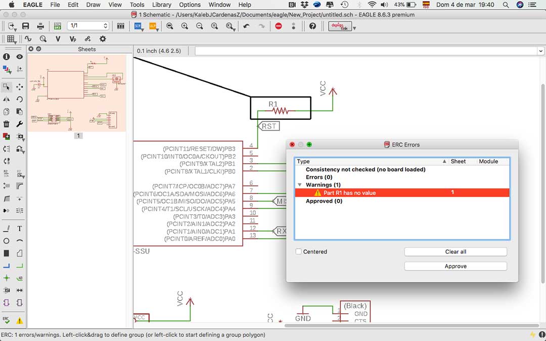
I began by making an ERC (Electric Rule Check) , this test helped me find out I haven’t placed the value to one of my resistances, I corrected the errors and continued.
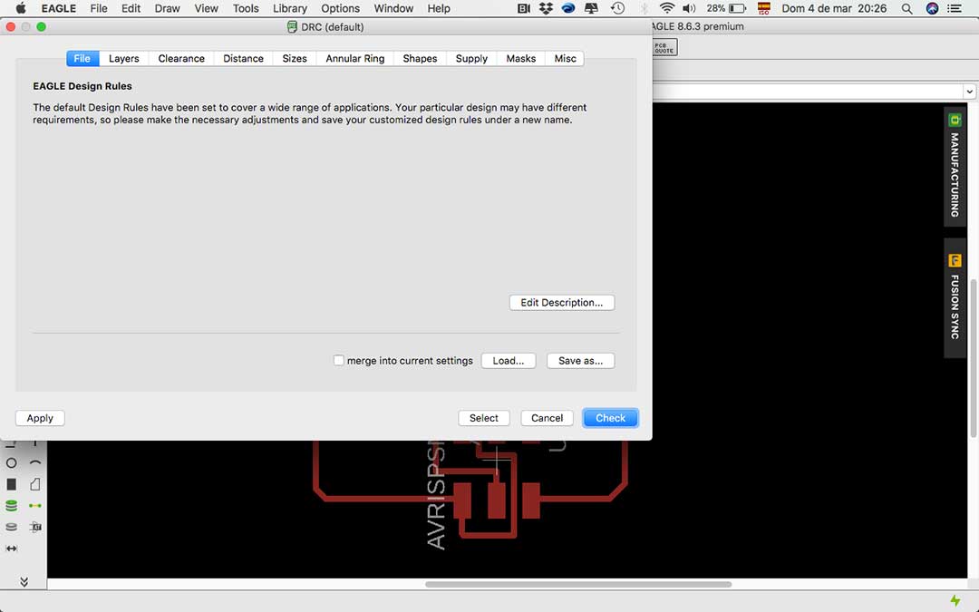
After that, I manage to set all my traces width with 1/64mill (0.4mm) and connected my board properly. Then, I made a DRC (Design Rule Check), I assigned the clearance for my traces, clicked on the “check” button and was good to go.
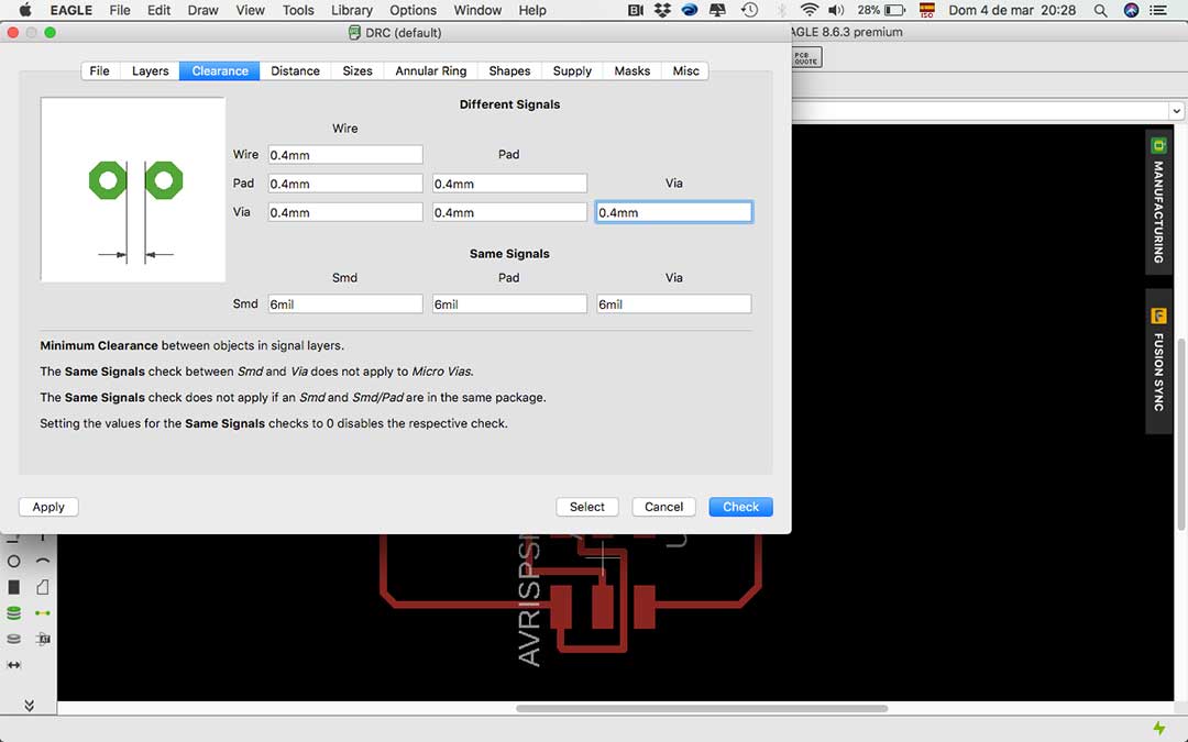
I had to change some clearance with some components that were going to give me trouble making the board, I made the correction them and continue.
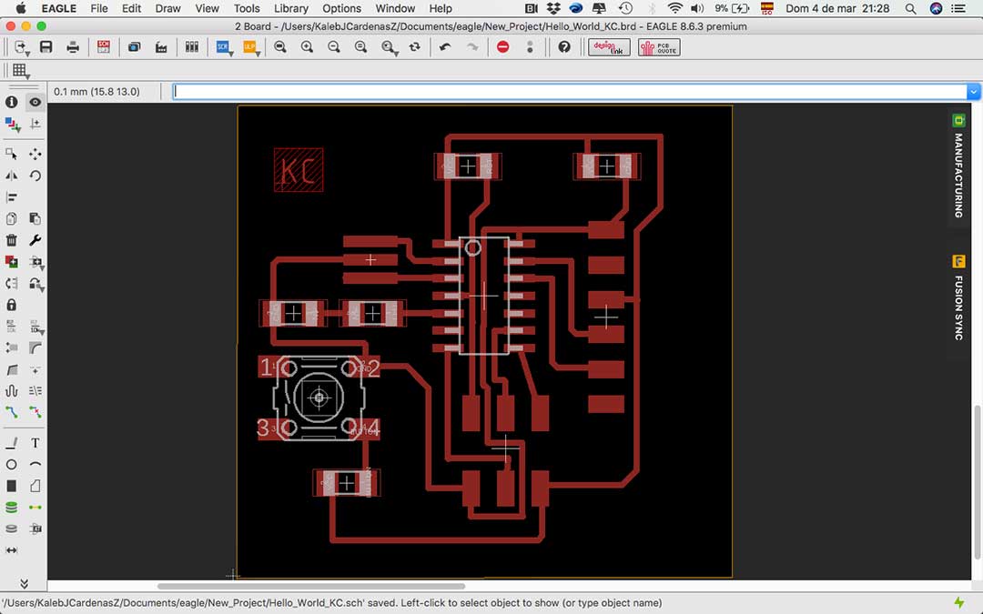
Finally, I decided to place a Ground plane that would help me optimize my board production, I gave it a 0.8mm offset between the traces so I could have enough space to solder the components.
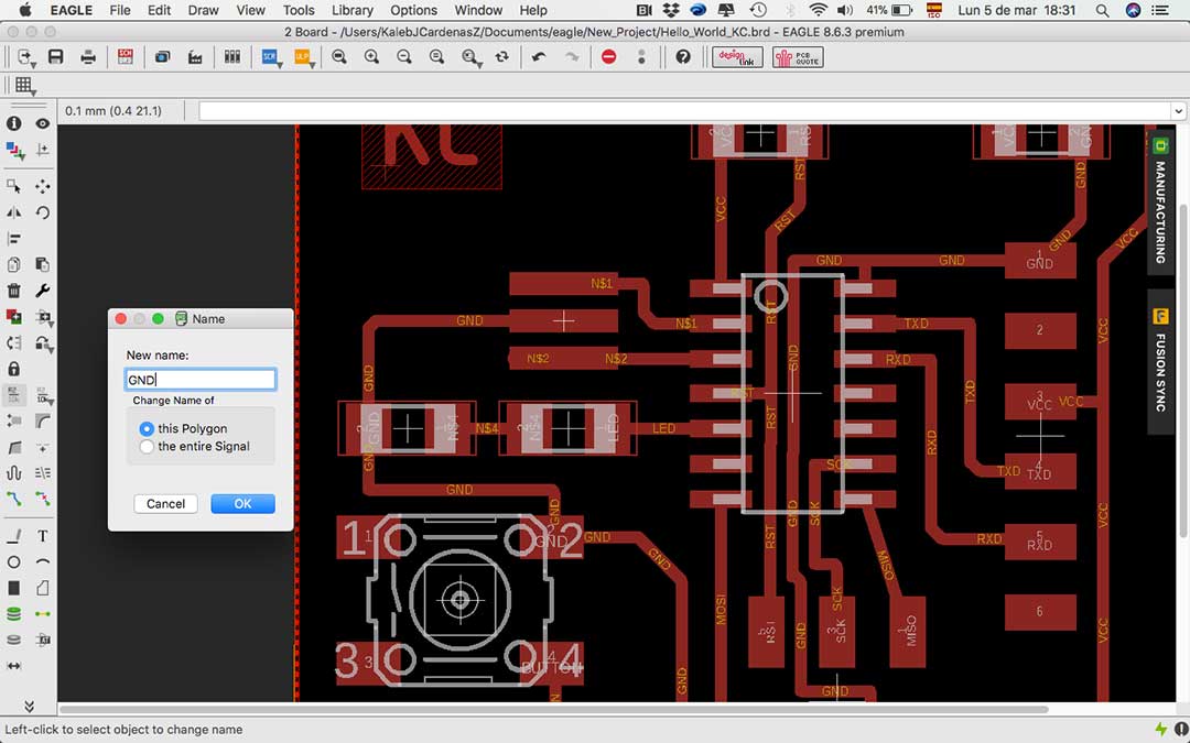
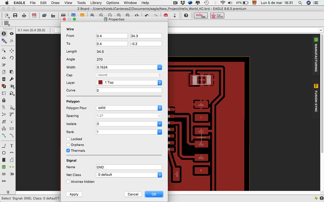
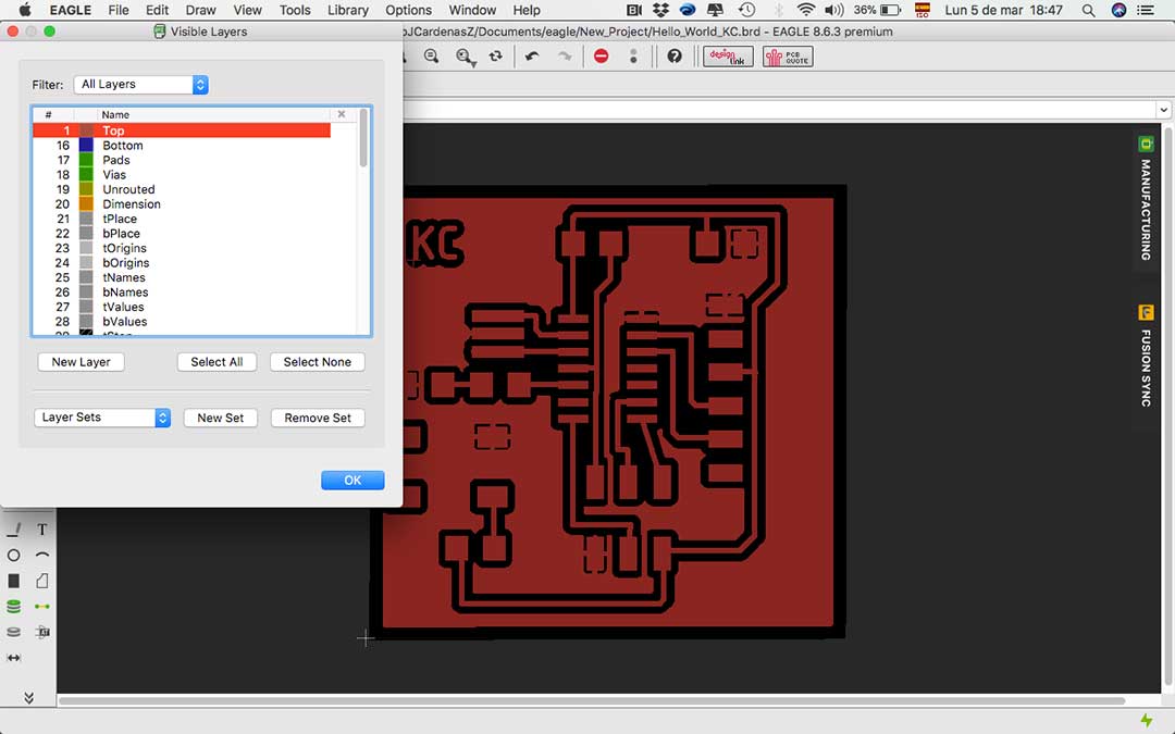
I am now ready to generate my production files.
Make it
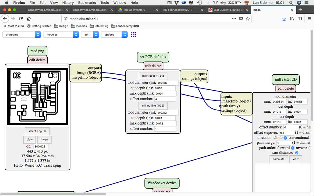
I exported my traces and outlines to png files, and then imported these files into mods in order to generate the g-code for the Roland machine. This process can also be read from my week 4 assignment.

I realized that I had exported my file with 300 Dpi to mods, this were not enough pixels because my trace wasn't correct, I then changed it to 1000 DPIS and it worked fine. I then exported my traces and outline files to the Roland.

Now is time to make the board. I followed the same steps from last time, first set my “origin” in X/Y and after in Z. I’m using the 1/64mill to make the trace. I turned on the Rolland Machine and start my code.
After the trace was finished I changed to 1/32in mill and cut out the outline. It also went well.
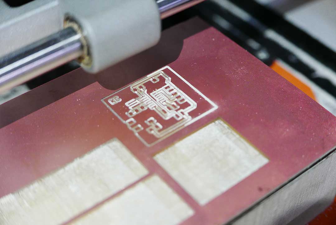
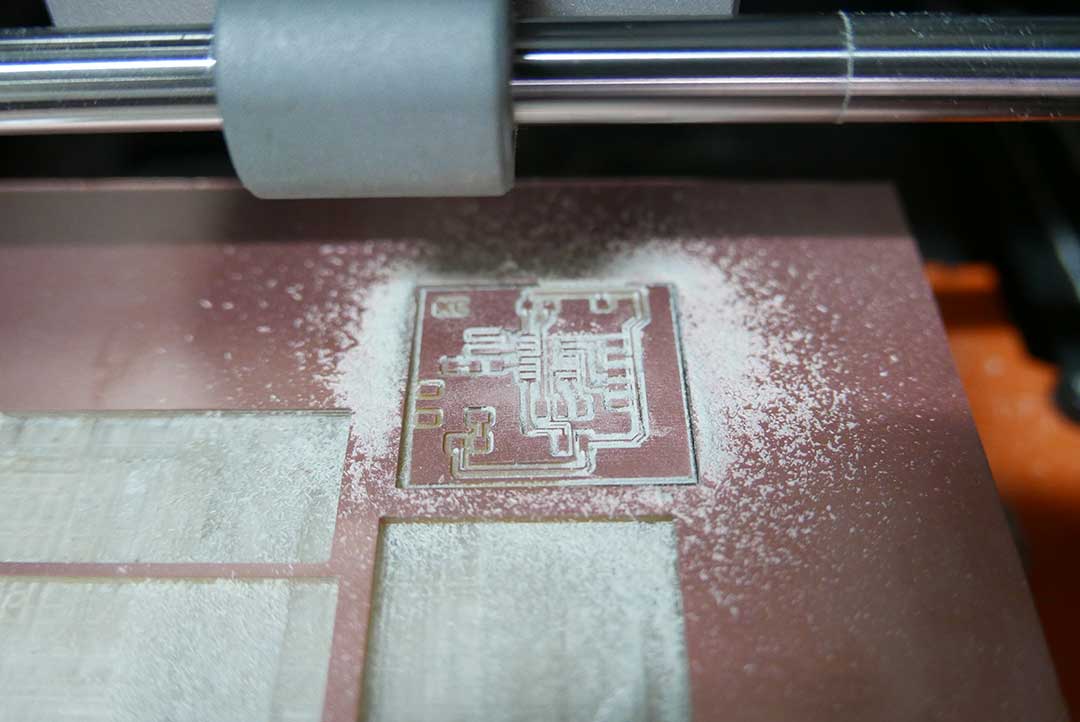
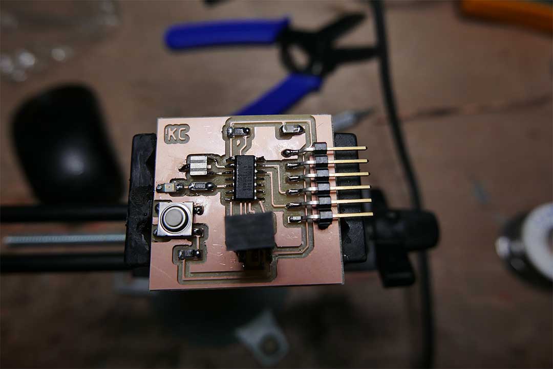
Luckily the board was successful, I then gathered all my components and began to solder. I used a similar order to solder my components from last time, first the smaller ones like resistors, LED and capacitors. Then came the ISP because later the Attiny would generate trouble due to the lack of space. Afterwards came the Attiny, button, resonator and FTDI.
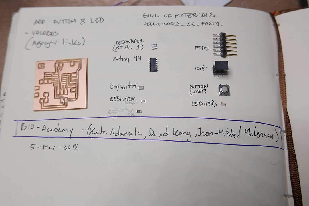
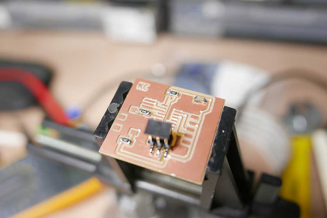
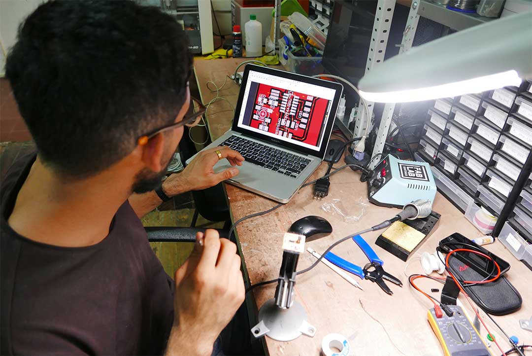
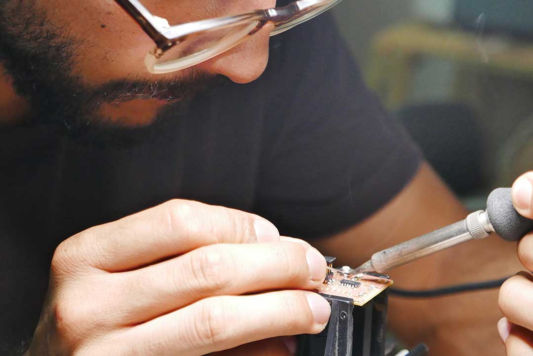
Finally after successfully soldering all my components and checking that I had no mistakes with my circuit using the Voltmeter, I continued to test my board.
Test
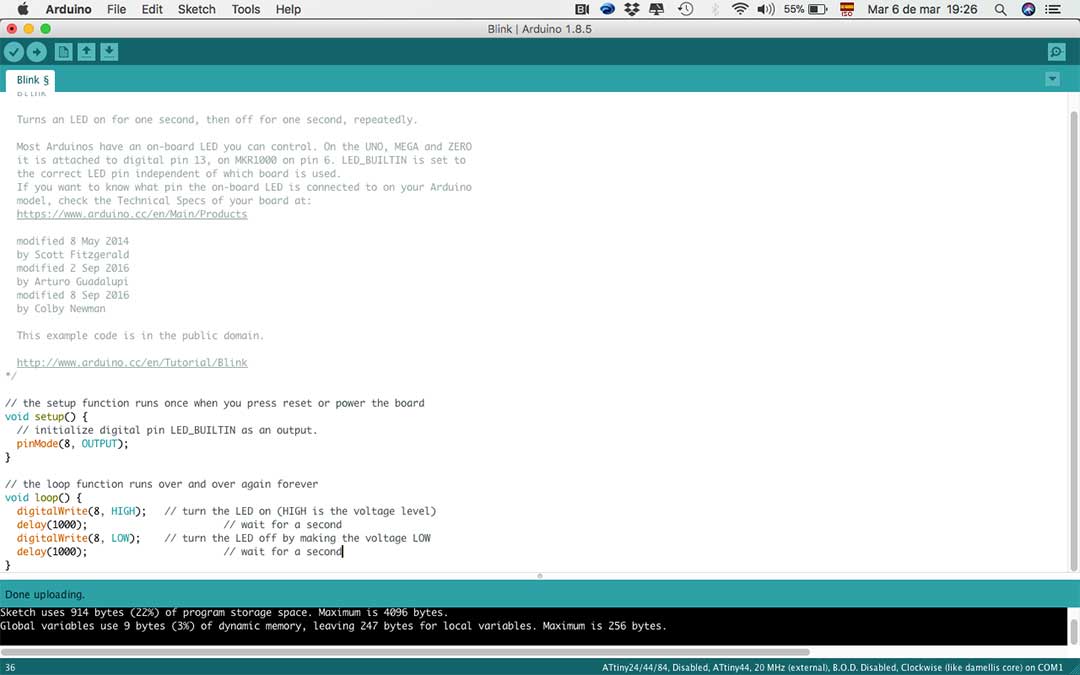
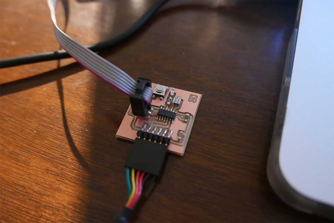
For the test I connected my board to the AVR ISP motherboard, I had green light and was happy because my board worked. Then, I decided to use Arduino software to program my board.
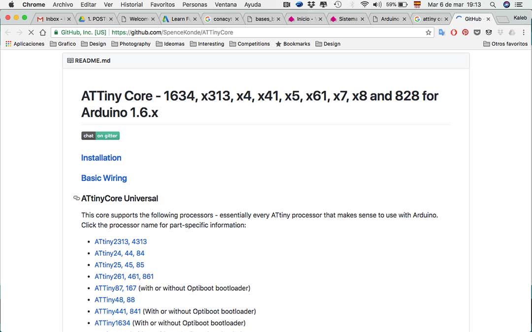
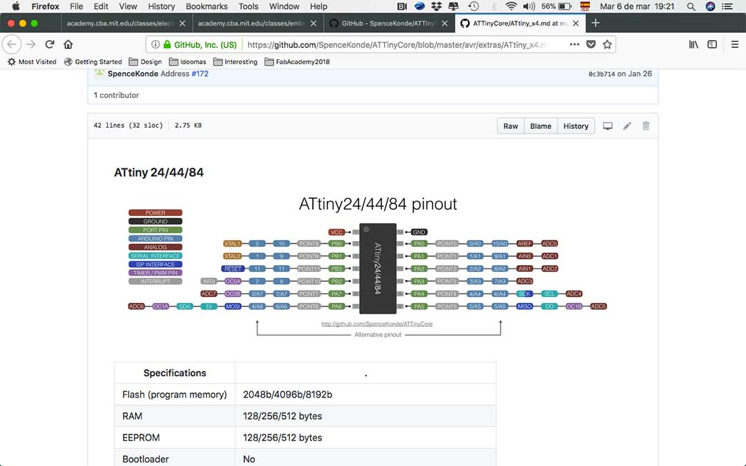
I downloaded it and then downloaded installed the Attiny core for Arduino in my computer. I checked the arduino board layout for the pinouts. Then chose the Attiny 44 in Arduino and chose the 20Mhx External.
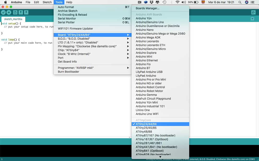
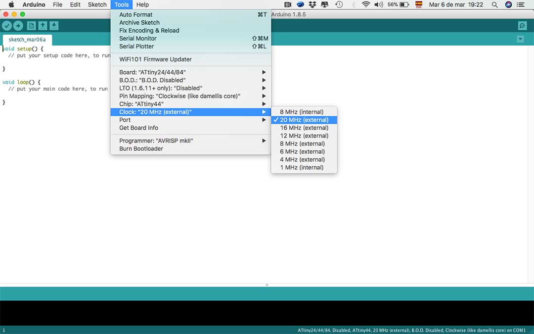
I tried an example from Arduino to program my LED, I set the pinmodes for my Outputs and Inputs coming from my board. I succeeded in uploading the file to my board, the test worked.
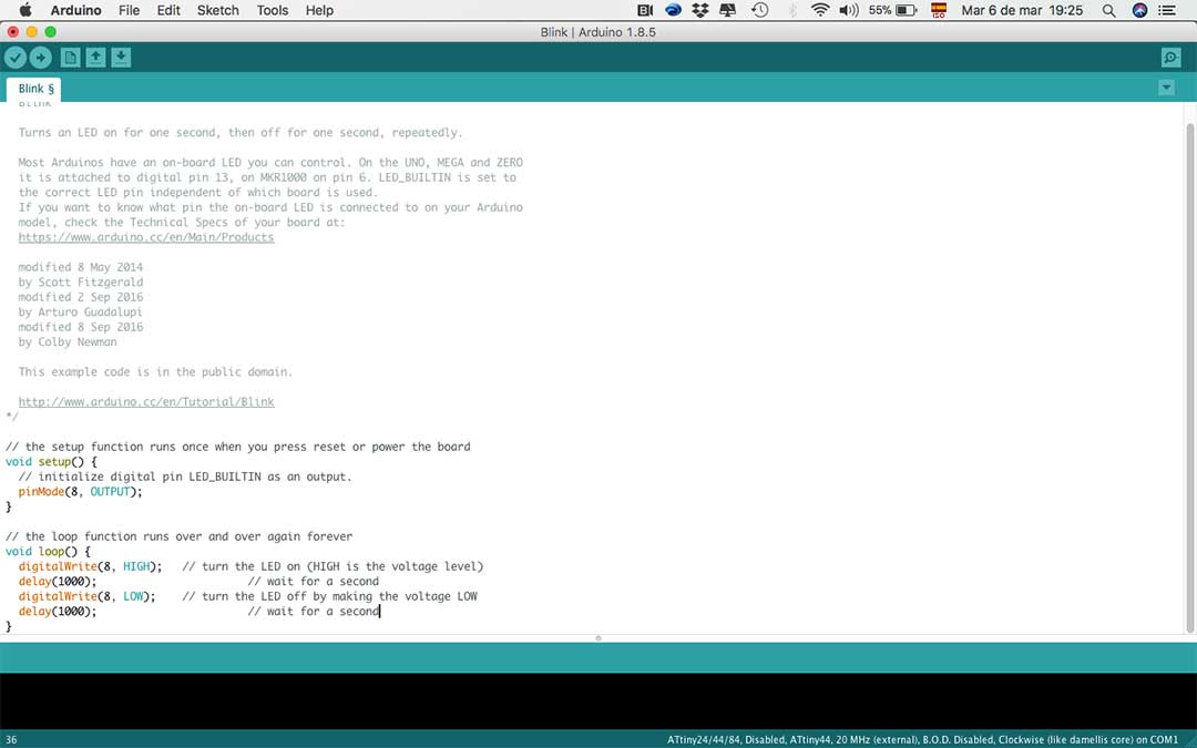
The green LED on my board turned on and off as the code was written, I was very pleased to see this, it was a long week and task but I manage to make it! ☺

FILES
All the files can be downloaded
here: