WEEK 4 - ELECTRONICS PRODUCTION
FOURTH ASSIGNMENT
- Characterize the specifications of your PCB production process.
- Make an in-circuit programmer by milling the PCB, then optionally trying other processes.
Group assignment:
Individual assignment:
CHARACTERIZE THE SPECIFICATIONS OF YOUR PCB PRODUCTION PROCESS - GROUP ASSIGMENT
For this week assignment I was a bit nervous, I had never made an electronic board or solder one, therefore, it was a big challenge for me to pull this off, I’m proud because I even push myself and manage to program my PCB.

To begin with, I read many of the websites suggested by Neil in order to understand what I was doing, after that, I had a good starting point.
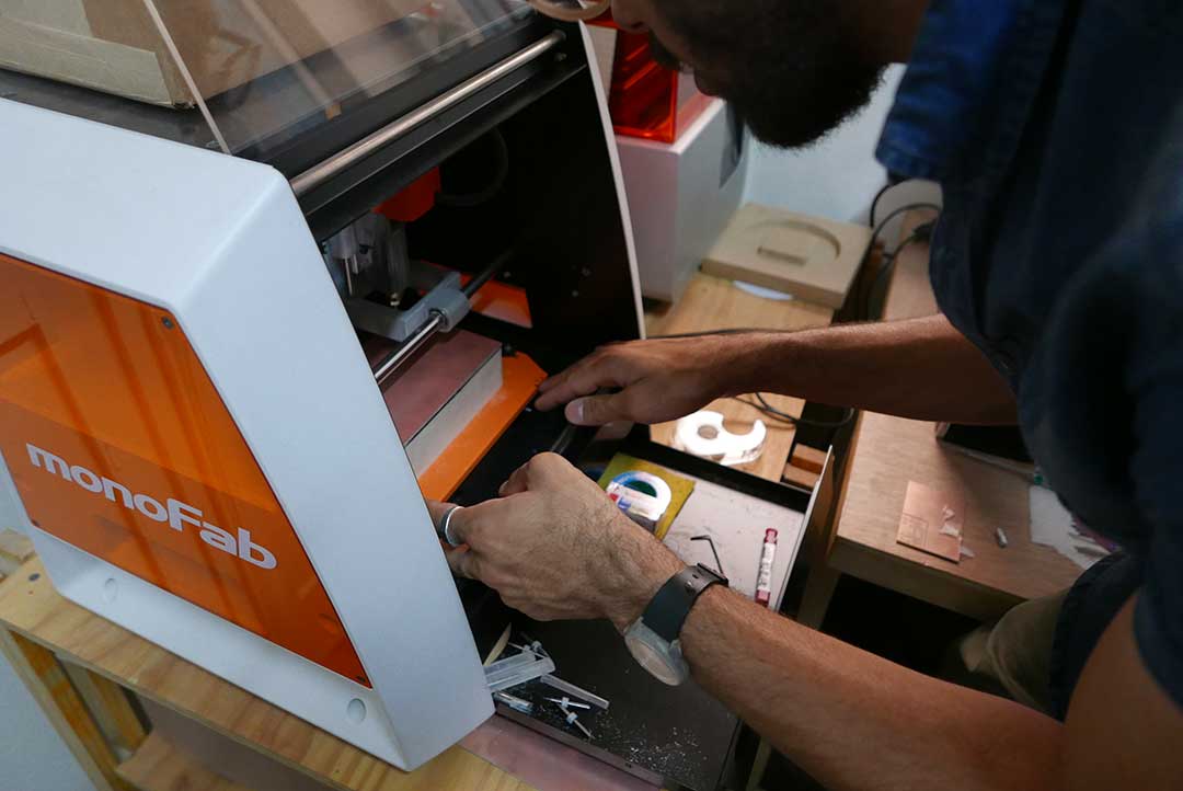
The first term I learned was PCB: Printed Circuit Board. The machine we use to mill the boards in our Fab Lab is a Roland monoFab SRM-20, we first explored the machine and learned how it worked and how to set up our tools.
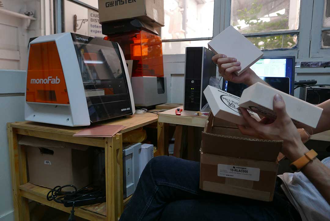
The base where you place the copper board is made of high-density foam. The Roland needs to be calibrated like any other CNC machine. To generate the g-code we need 3 types of files:
There are two types of elements on boards:
Also, PCB´s can have insulation coatings and silkscreens to be able to print info like logos or texts on boards.
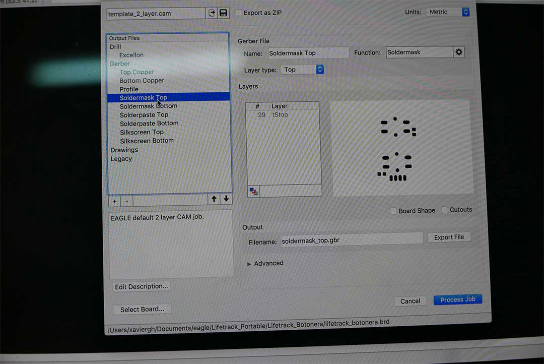
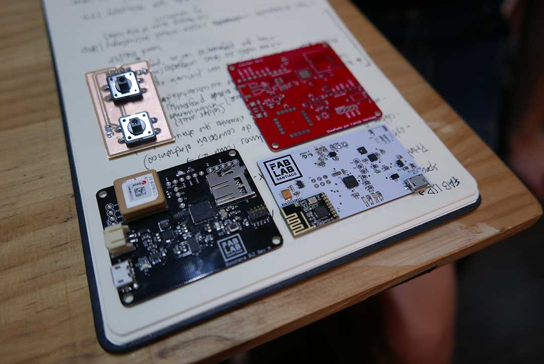
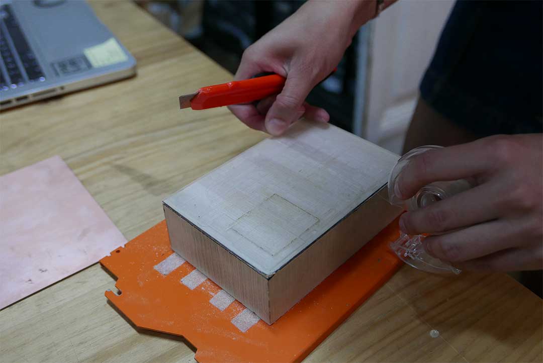
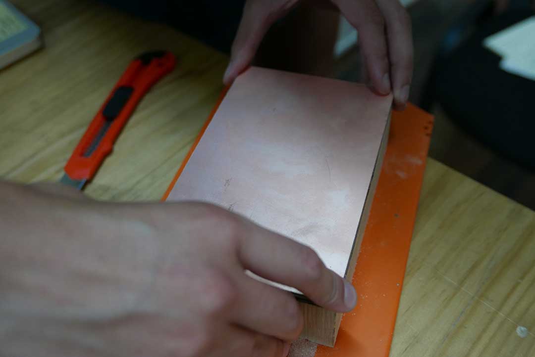
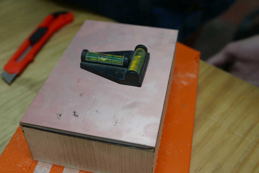
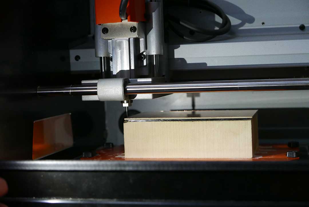
After this introduction it was time to set up the machine, we first placed a new copper sheet on the foam with double tape, we made sure it was leveled and then mounted it to the bed.
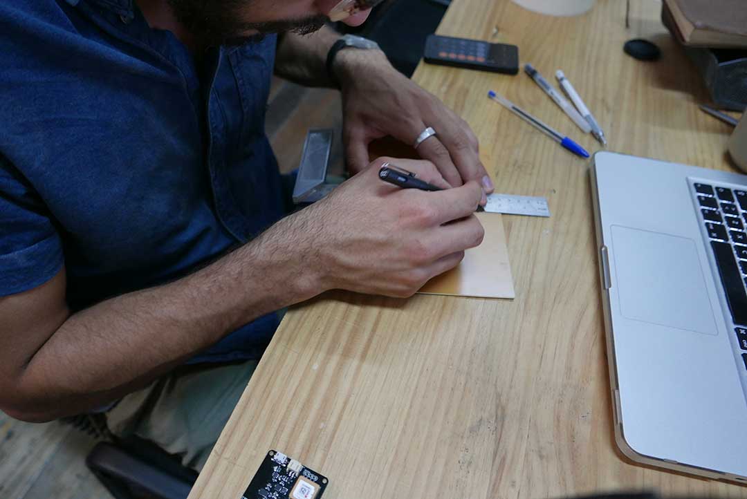
Then it was time to set up the mills, the 2 most used mills for this kind of boards are:
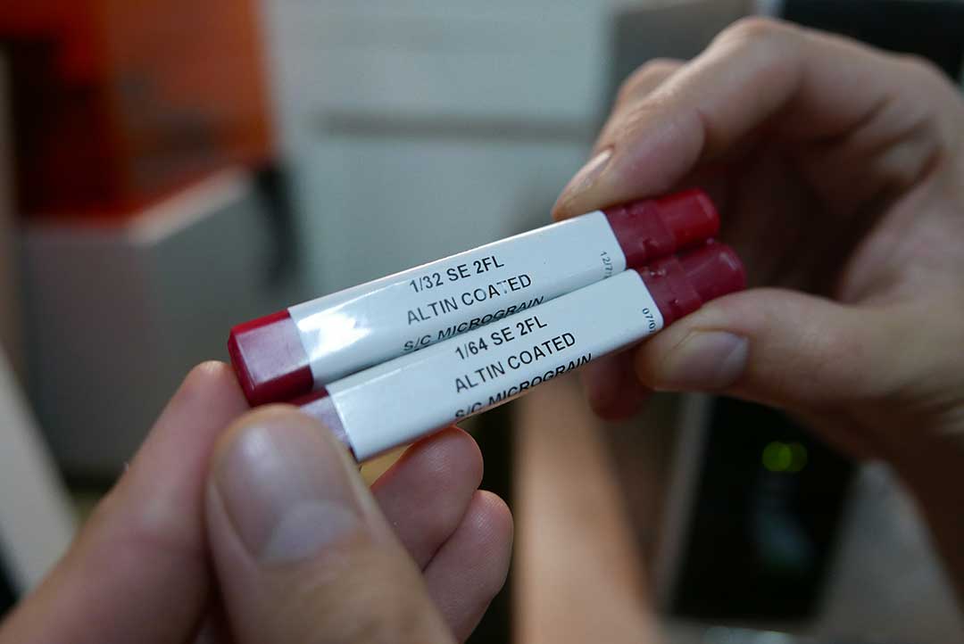
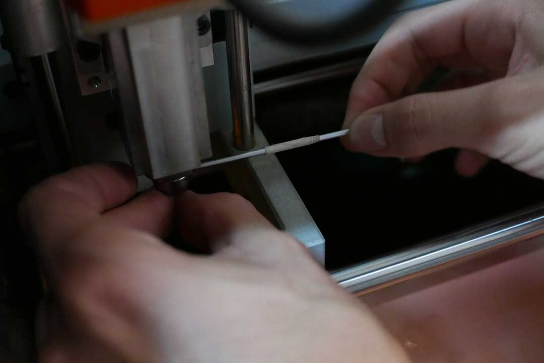
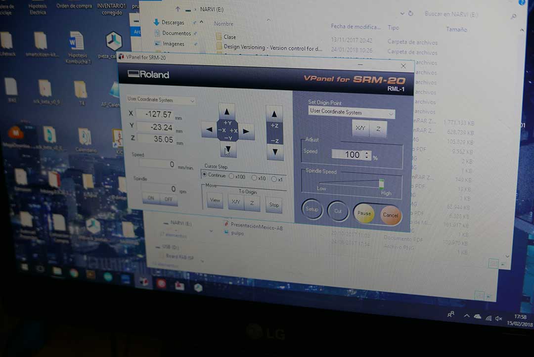
Then it was time to set up the machine for milling, we mounted the 1/64-inch mill and set our “origin” on X-Y and Z-axis. We had to be very careful with the mills, since they are very thin, they can break pretty easily.
Now the machine is ready to fabricate.
MAKE AN IN-CIRCUIT PROGRAMMER BY MILLING THE PCB
For this assignment we decided to go with the FabTinyISP, this file was modified by Bas, considering that it is a good PCB to start with as a beginner.
The files inside the .rar file are:
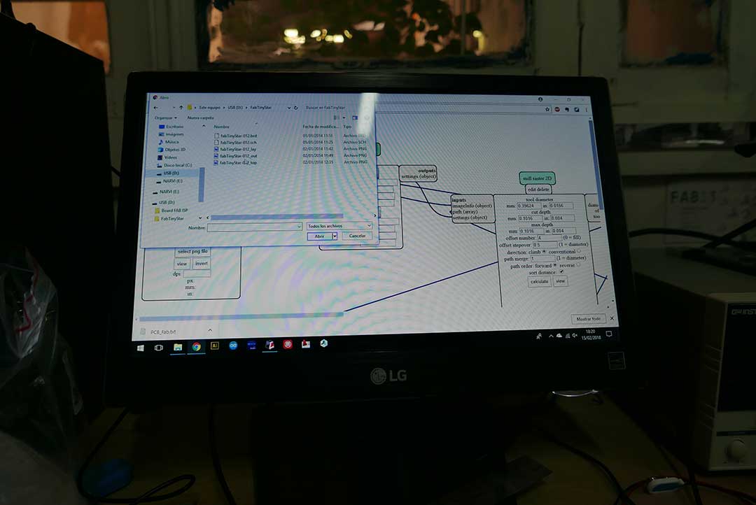
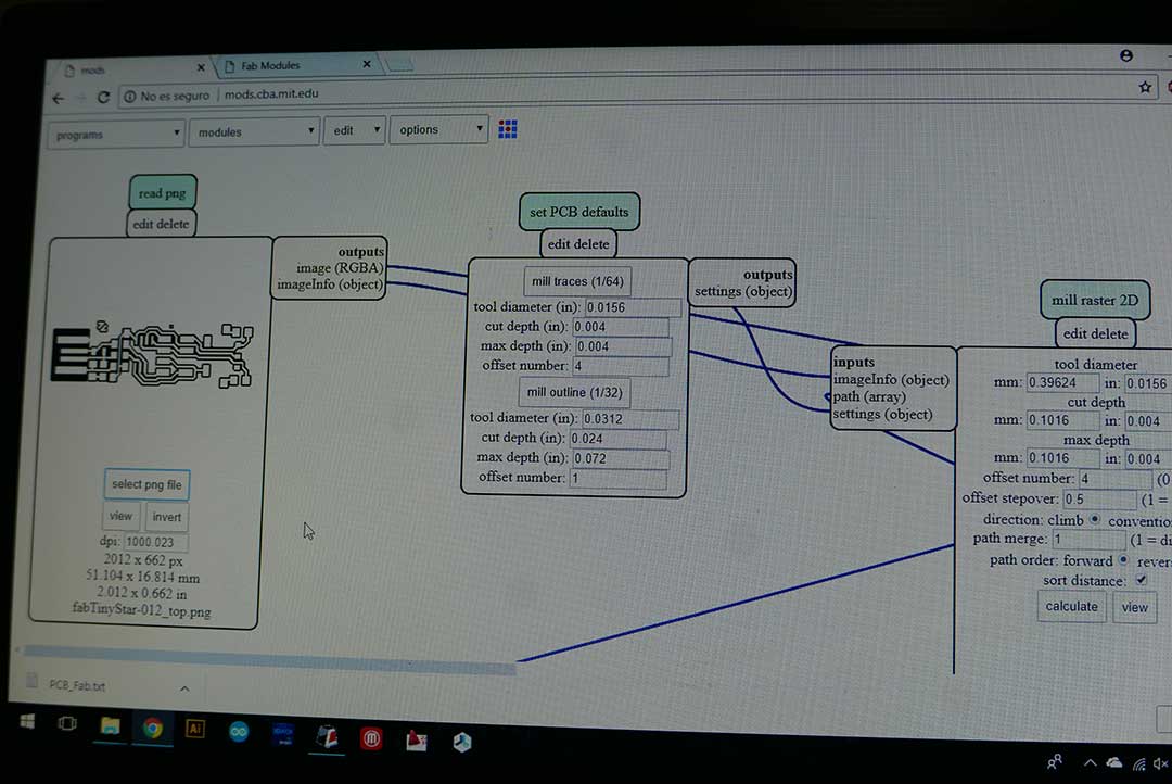
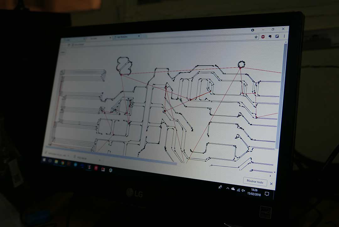
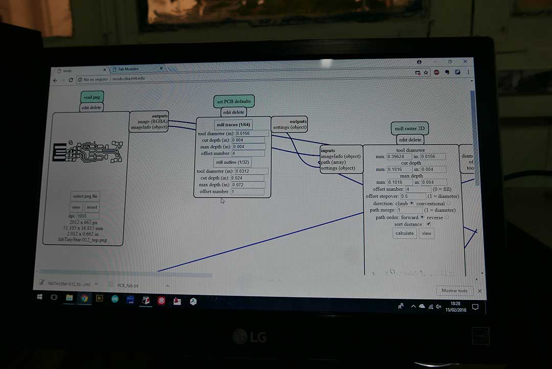
Then it was time make the g-code, I decided to use mods. To make the inside cut I uploaded the file named “top” and for the outline I used the file “out”. Each file with it´s specific mill traces, then added a module and the file was created.
Then the first file was sent to the machine with the 1/64-inch mill, this created the inside cut trace.
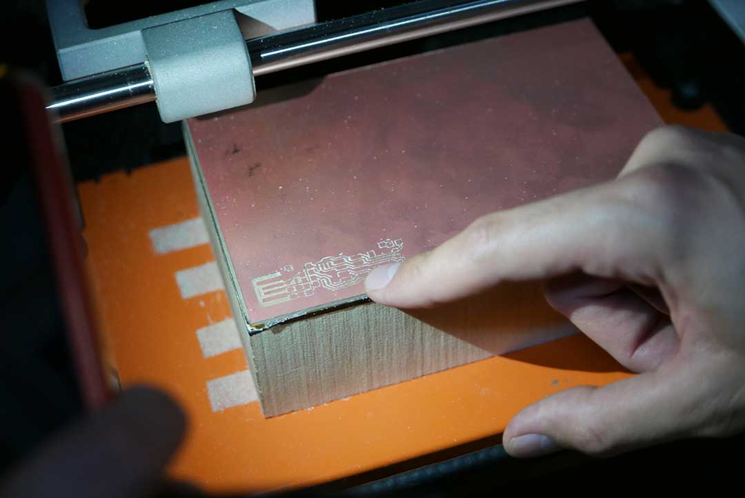
Once finished I changed the mill for the 1/32-inch and began to cut the outline. One of the holes in the board was missing. This happened because the code cut the outline first and not the holes, this made the PCB move and the mill missed the second hole.
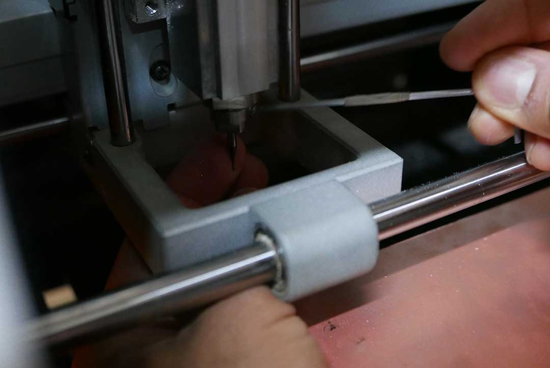
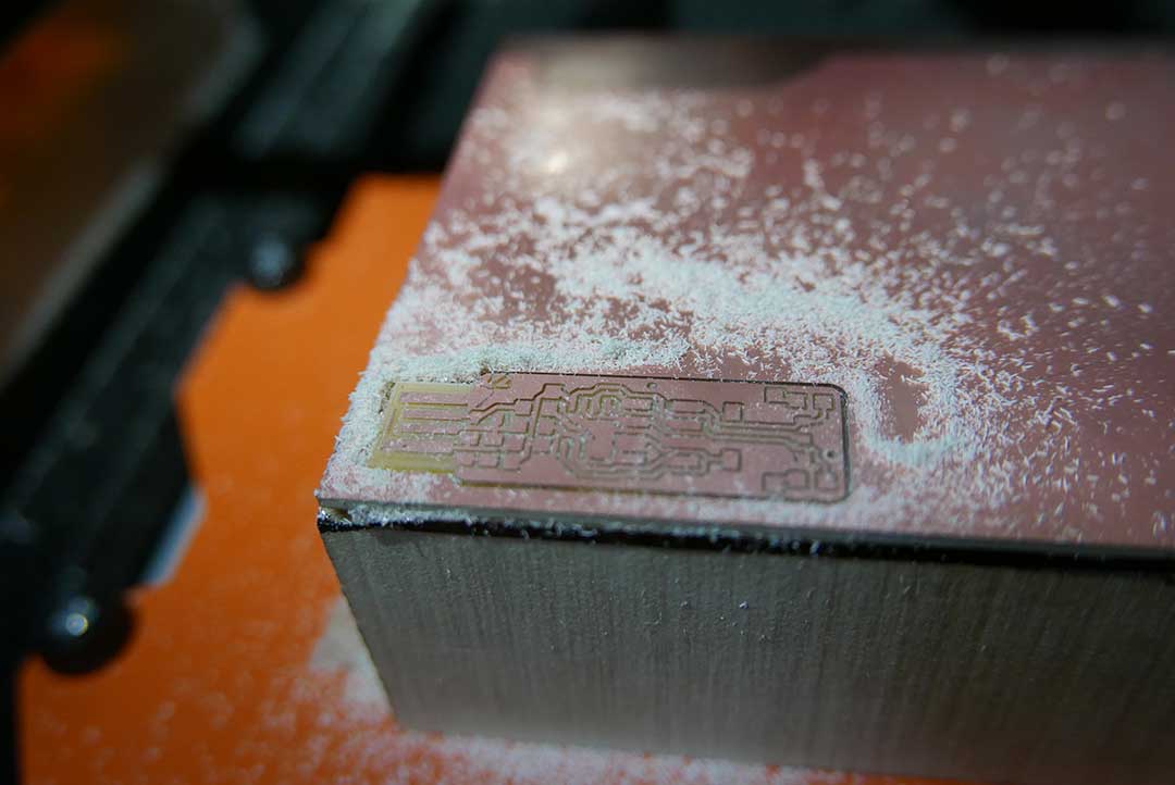
The way to correct this is to send the outline file in reverse, this will make the machine to make the holes first and then the outside cut.
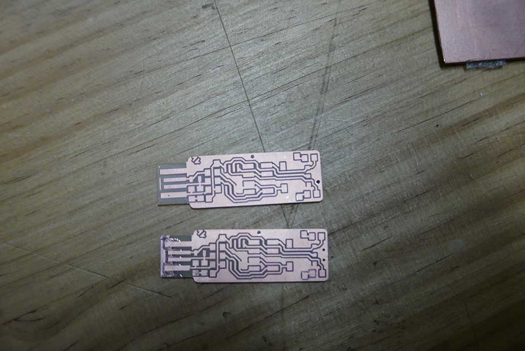
SOLDERING AND PUTTING IT ALL TOGETHER
This part of the exercise was one of the most difficult because it requires concentration in many steps, first you need to be very organized with your “bill of materials”. You can easily get confused with the components and also place them in the wrong order.
Also soldering requires great precision, you can ruin your board if the solder wire goes to another division in you PCB. Great attention is essential.
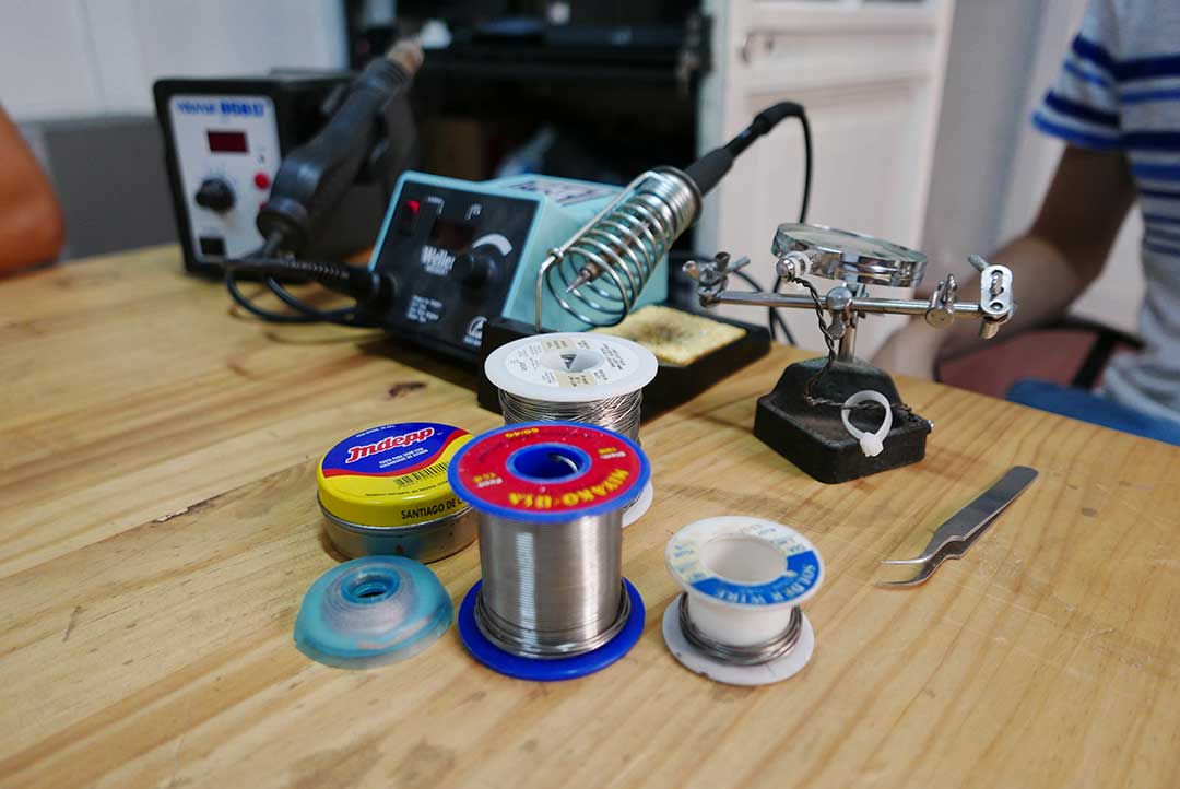
Some of the tools required to solder are:
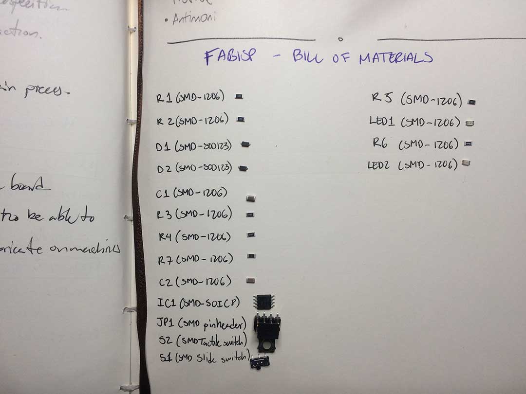
Then it was time to choose the components for the FabTinyISP, these are the components: "Bill of Materials". We have all the components at our Fab Lab, so then I began to classify them and prepared to solder.
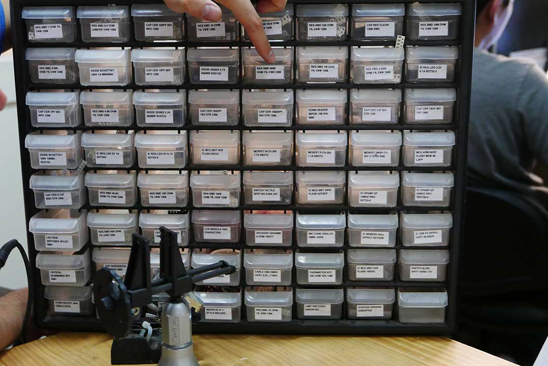
After preparing everything to solder, I decided to practice a bit. I placed many components trying to be as clean as possible with the solder wire, I messed up many times but I started to gain confidence and balance in my hands.
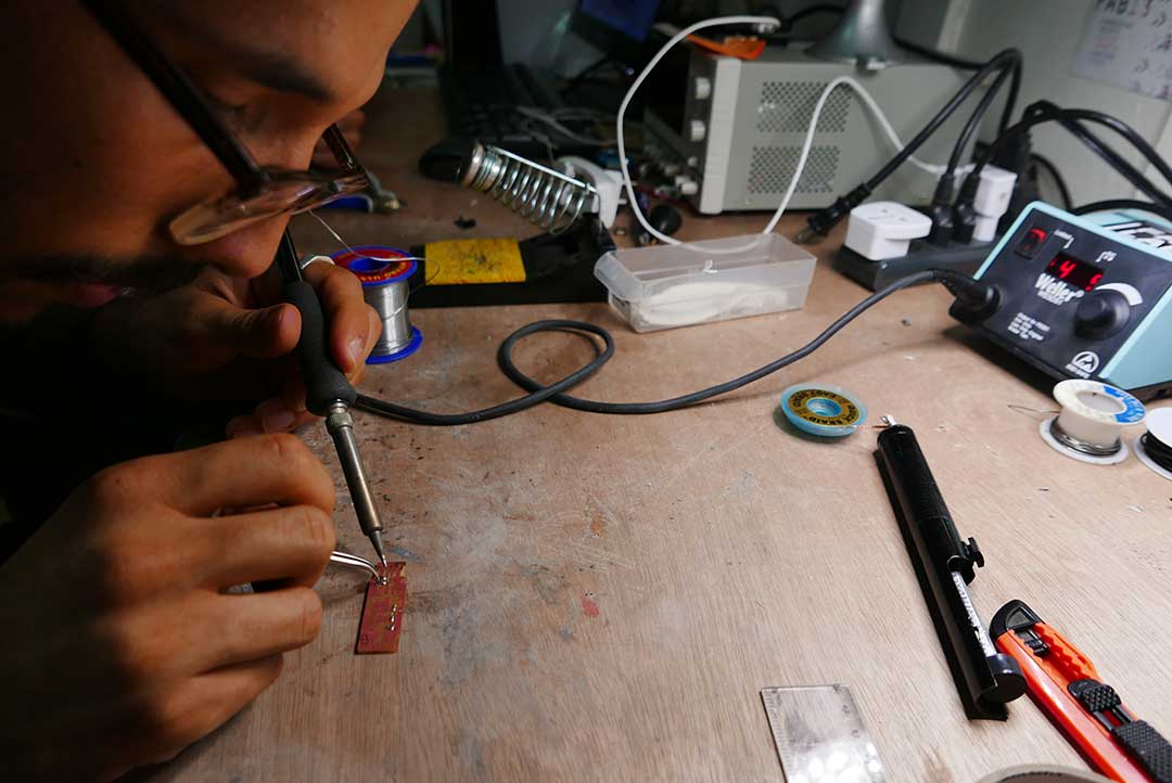
Then came the chance to make my PCB board. I was still a bit nervous but motivated about the idea.
The right way to solder is to have you solder station at the right temperature (a suggestion is 450ºC or 500ºC), then always pre-heat the copper, this will make the solder wire attach to it more easily.
Then hold your piece with the tweezers in one hand and solder wire in the other, start melting the wire with the solder station and try to make a rounded but flat surface. This will make the parts of your board attach perfectly and also make it cleaner.
The order I followed to have a cleaner solder was: first the resistors, followed by the diodes and capacitors. Then I solder the ATTiny 45 and the 2x4 jumper. After came the tactile switch, followed by the slide switch (If you made it this far, finishing the rest of the components is easy). To finish, I placed the LEDS and ended my board with the last resistors.
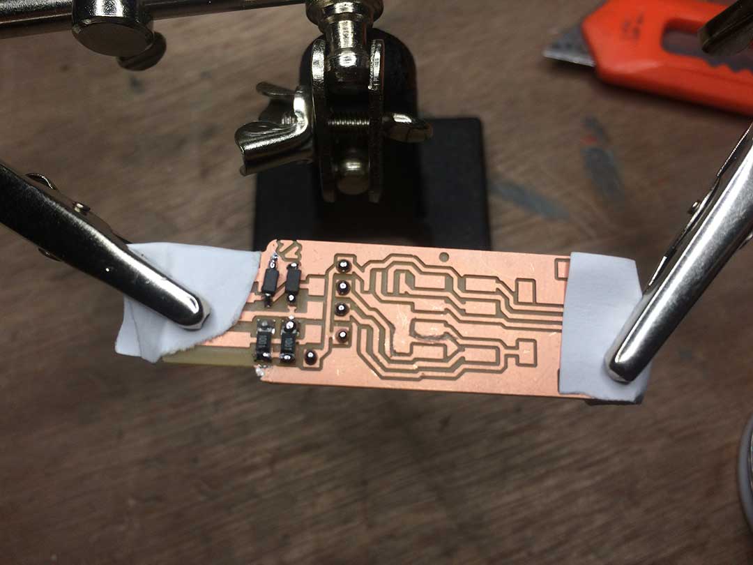
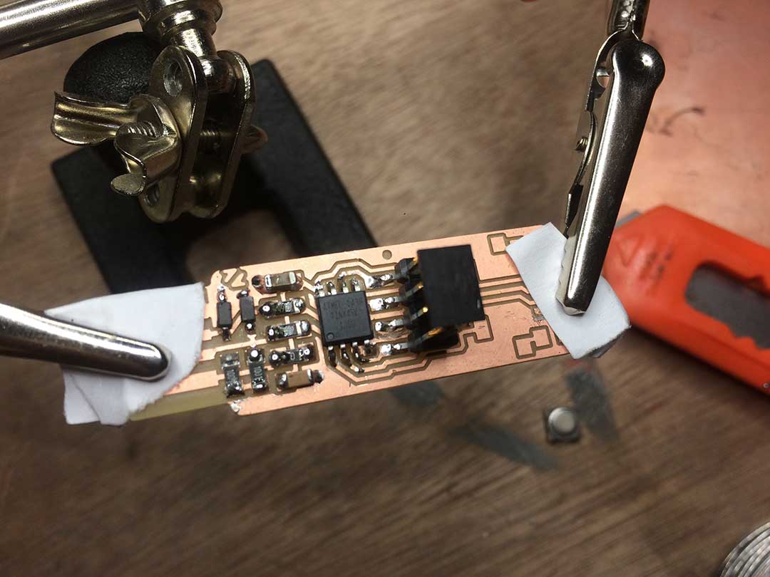
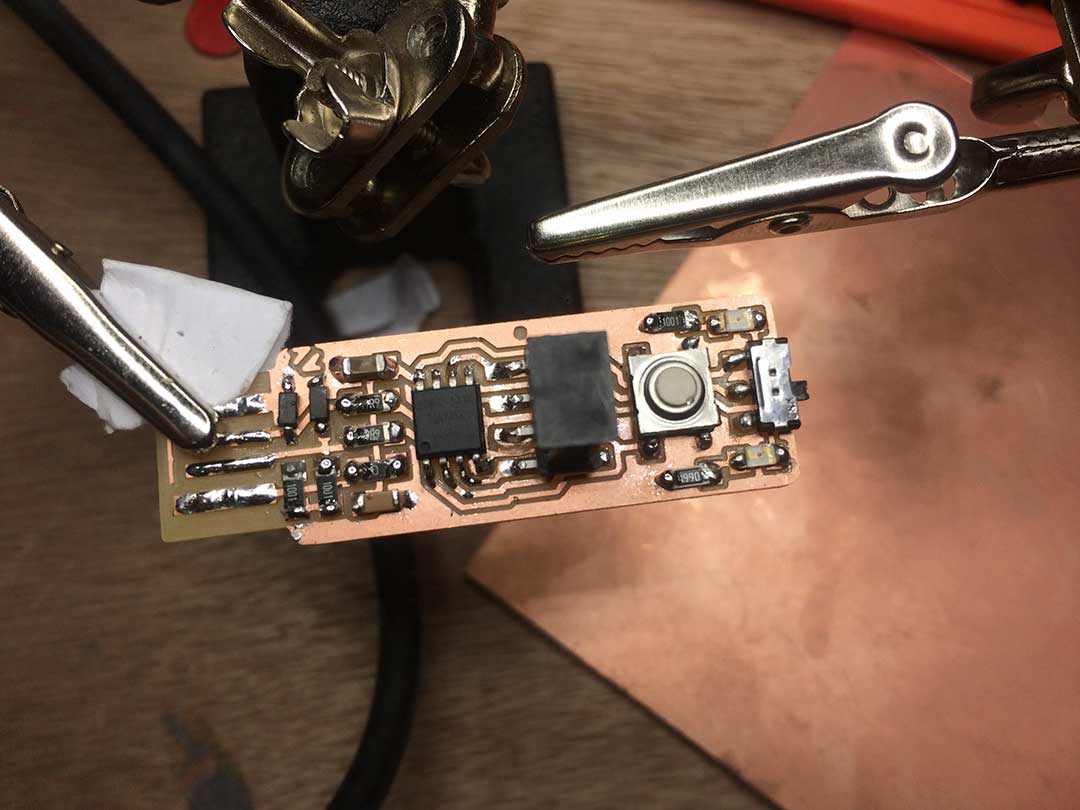
Then finally I checked my board with a DMM, and I was glad to realize there was no problem with the PCB. ☺
PROGRAMMING MY FABTINYISP
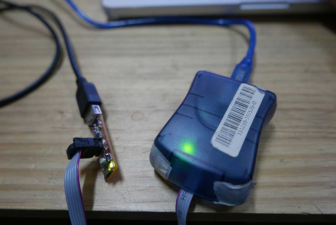
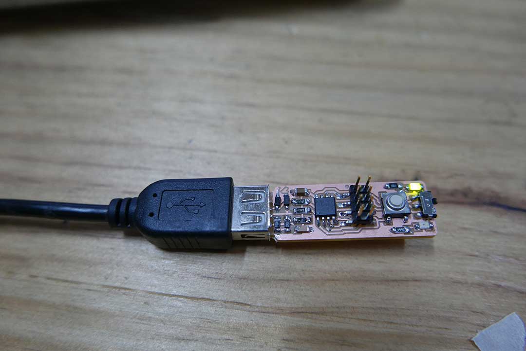
I plug my PCB to the USB AVRISP, then to my computer and it turned on, this means that my board is well solder and I can start programing it.
I first began by installing some of the requirements to create the right environment to program the board. This included “make”, "avr-gcc" and "avrdude". Since I’m programing with a AVRISP, I needed to assign it to my terminal with "avrisp2 -P/dev/ttyACM0 -b19200".
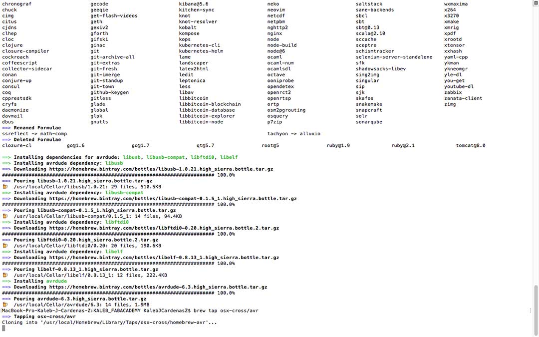
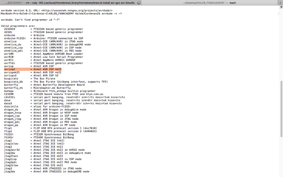
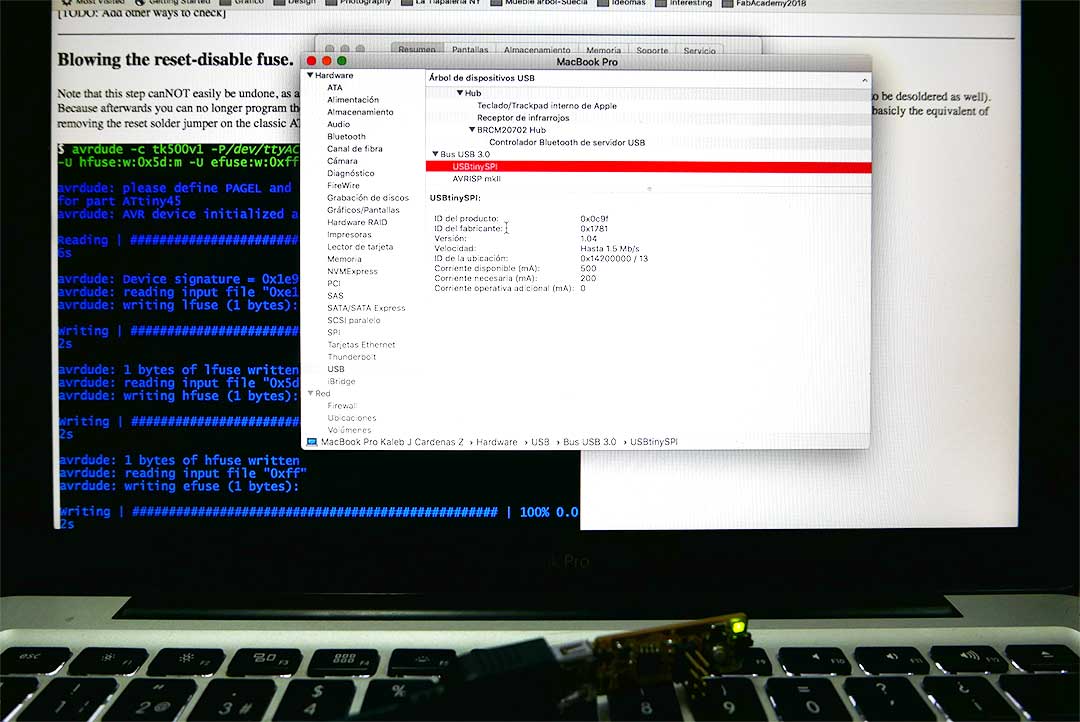
After that I programed the fuses with this code: avrdude -c avrisp2-P/dev/ttyACM0 -b19200 -p t45 -V -U lfuse:w:0xe1:m -U hfuse:w:0xdd:m -U efuse:w:0xff:m. So good so far.
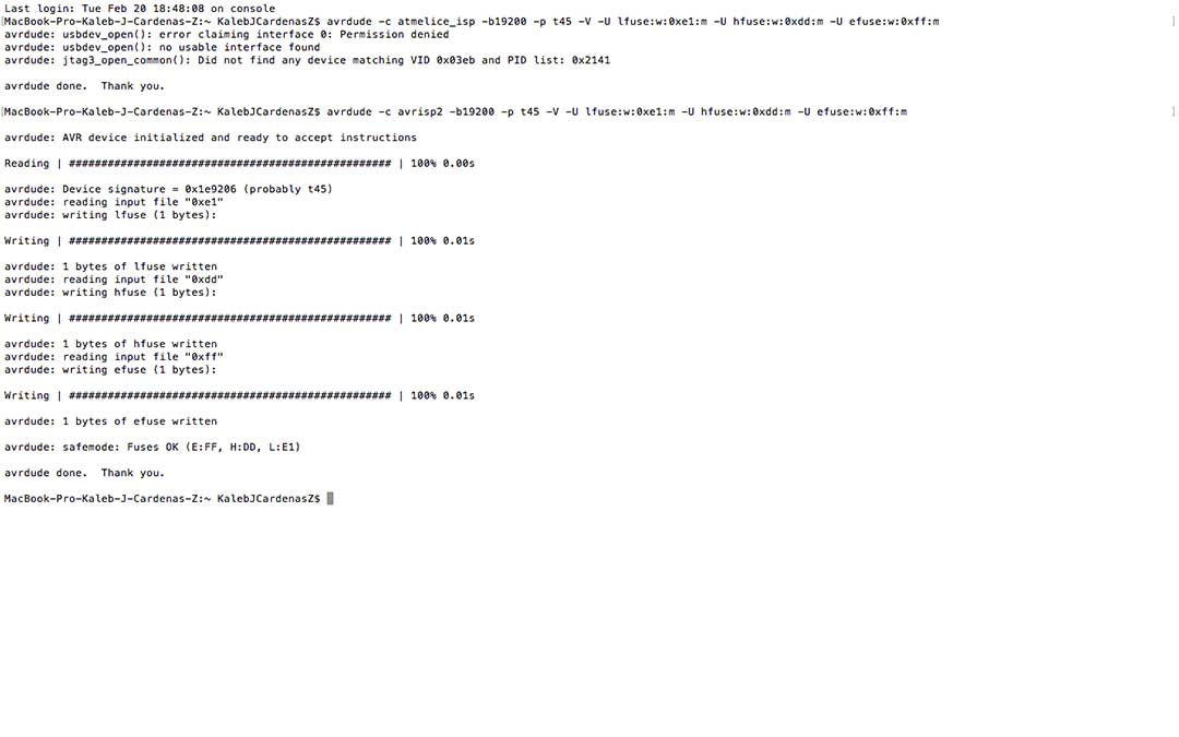
Now that I had a working programmer I could obtain the firmware. I downloaded the vusbtiny-fabtinystar.zip and upacked it in my terminal with this line: $ wget http://www.simpleavr.com/avr/vusbtiny/vusbtiny.tgz
I edited the usbconfig.h to swap the pins used for USB communication: //#define USB_CFG_DMINUS_BIT 4 #define USB_CFG_DMINUS_BIT 3 //#define USB_CFG_DPLUS_BIT 3 #define USB_CFG_DPLUS_BIT 4
To flash the firmware I enter “make install” command: $ make install. The Leds blinked in both boards, I then finished my process.
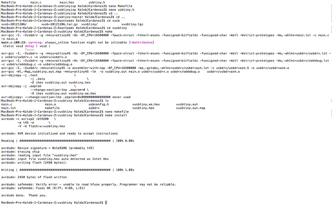
I then became owner of a new In-System-Programmer. I had a lot of help and tuition from our electronic engineer, Xavier García, from our Fab Lab. I don’t think I would have been able to pull this off without him.
CONCLUSION
My conclusion from this assignment is that I need to concentrate more on my programming skills, I think I manage to learn to solder pretty well being the first time I did it. I honestly enjoyed this but it was still a bit stressful, luckily it all worked fine in the end.
FILES
All the files can be downloaded
here: