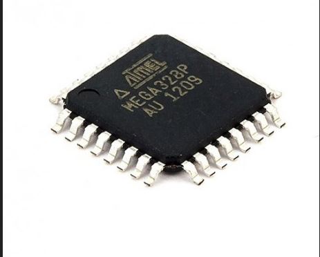
intoduction to microcontroller.
Features.
• High Performance, Low Power AVR® 8-Bit Microcontroller.
• Advanced RISC Architecture.
– 131 Powerful Instructions – Most Single Clock Cycle Execution.
– 32 x 8 General Purpose Working Registers.
– Fully Static Operation.
– Up to 20 MIPS Throughput at 20 MHz.
– On-chip 2-cycle Multiplier.
• High Endurance Non-volatile Memory Segments.
– 4/8/16/32K Bytes of In-System Self-Programmable Flash progam memory(ATmega48PA/88PA/168PA/328P.
– 256/512/512/1K Bytes EEPROM (ATmega48PA/88PA/168PA/328P).
– 512/1K/1K/2K Bytes Internal SRAM (ATmega48PA/88PA/168PA/328P).
– Write/Erase Cycles: 10,000 Flash/100,000 EEPROM.
– Data retention: 20 years at 85°C/100 years at 25°C(1).
– Optional Boot Code Section with Independent Lock Bits
In-System Programming by On-chip Boot Program True Read-While-Write Operation .
– Programming Lock for Software Security.
• Peripheral Features.
– Two 8-bit Timer/Counters with Separate Prescaler and Compare Mode.
– One 16-bit Timer/Counter with Separate Prescaler, Compare Mode, and Capture Mode.
– Real Time Counter with Separate Oscillator.
– Six PWM Channels.
– 8-channel 10-bit ADC in TQFP and QFN/MLF package
Temperature Measurement.
– 6-channel 10-bit ADC in PDIP Package
Temperature Measurement.
– Programmable Serial USART.
– Master/Slave SPI Serial Interface.
– Byte-oriented 2-wire Serial Interface (Philips I2
C compatible).
– Programmable Watchdog Timer with Separate On-chip Oscillator.
– On-chip Analog Comparator.
– Interrupt and Wake-up on Pin Change.
• Special Microcontroller Features.
– Power-on Reset and Programmable Brown-out Detection.
– Internal Calibrated Oscillator.
– External and Internal Interrupt Sources.
– Six Sleep Modes: Idle, ADC Noise Reduction, Power-save, Power-down, Standby,
and Extended Standby.
• I/O and Packages.
– 23 Programmable I/O Lines.
– 28-pin PDIP, 32-lead TQFP, 28-pad QFN/MLF and 32-pad QFN/MLF
.
• Operating Voltage:
– 1.8 - 5.5V for ATmega48PA/88PA/168PA/328P
.
• Temperature Range:.
– -40°C to 85°C.
• Speed Grade:
– 0 - 20 MHz @ 1.8 - 5.5V.
• Low Power Consumption at 1 MHz, 1.8V, 25°C for ATmega48PA/88PA/168PA/328P:
– Active Mode: 0.2 mA
– Power-down Mode: 0.1 µA
– Power-save Mode: 0.75 µA (Including 32 kHz RTC)
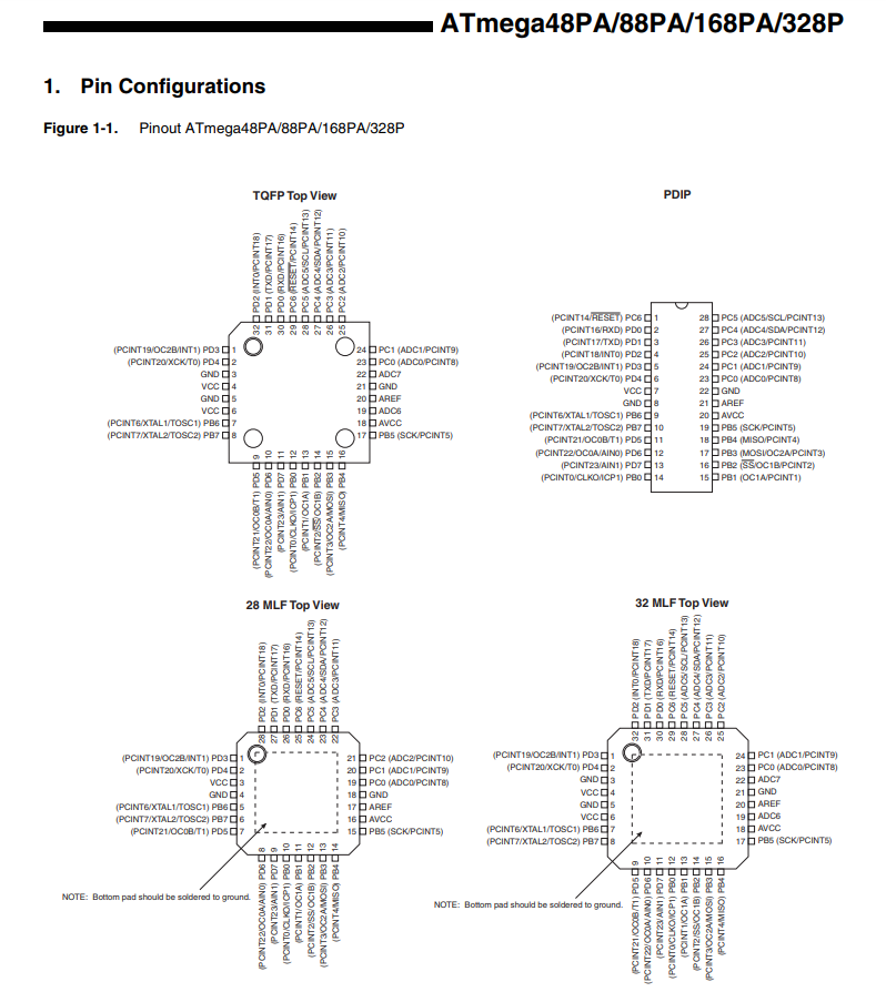
pin out of microcontroller
you can downloard the datasheet of Atmega 328p click here
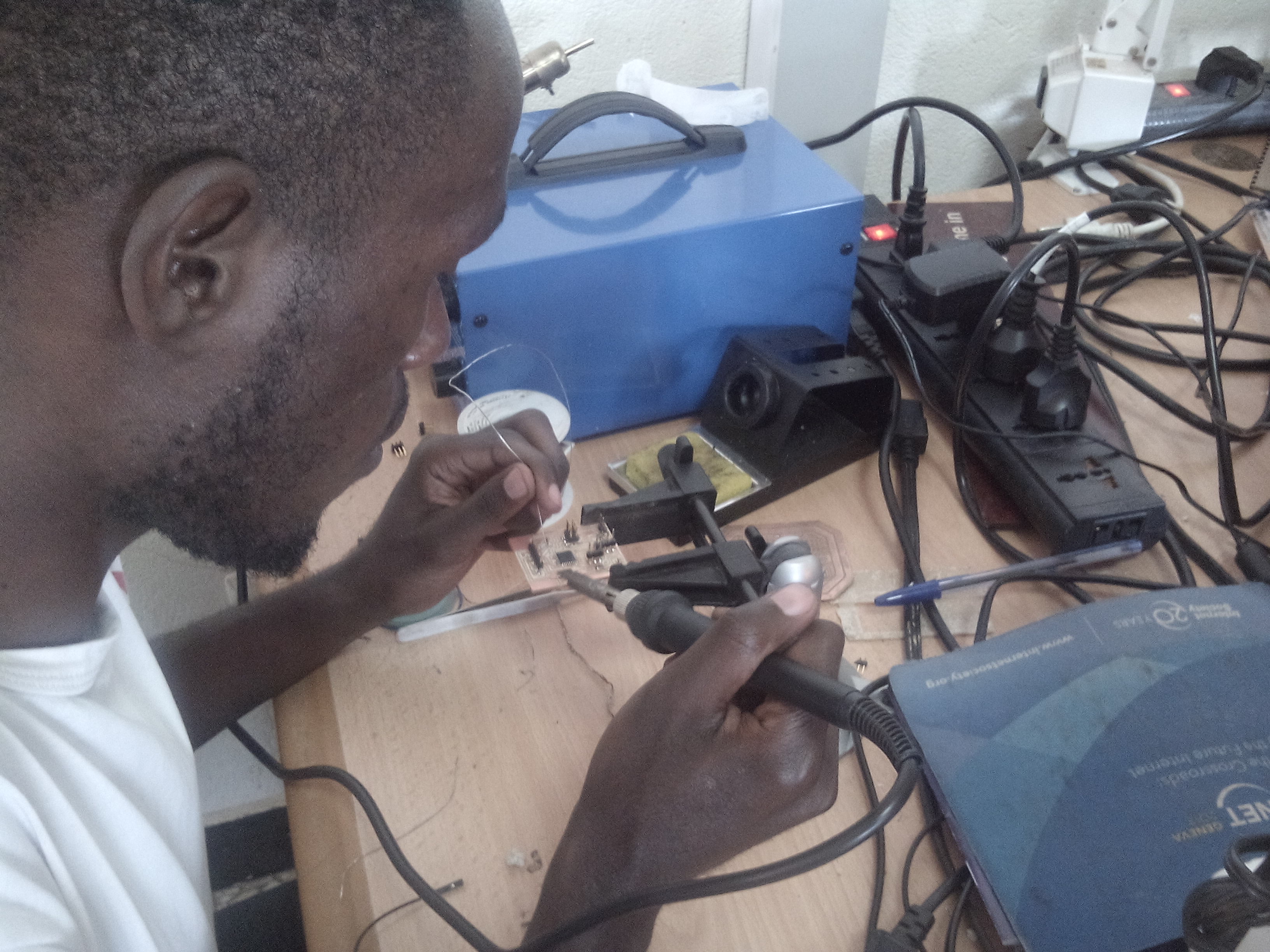
in that embedded programming i can programme my controller of my project i can begin our circuit.
we can begin to skech in software called eagle
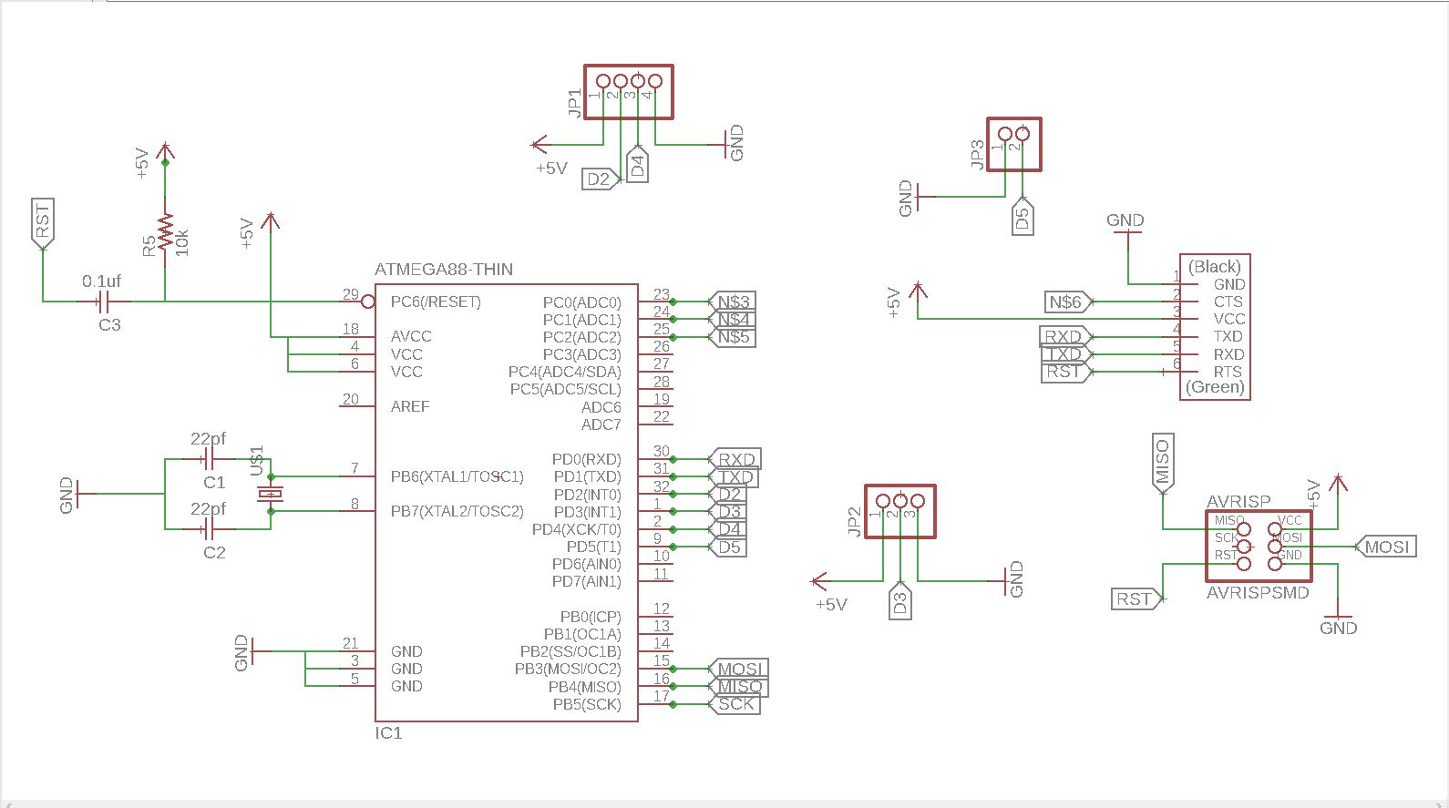
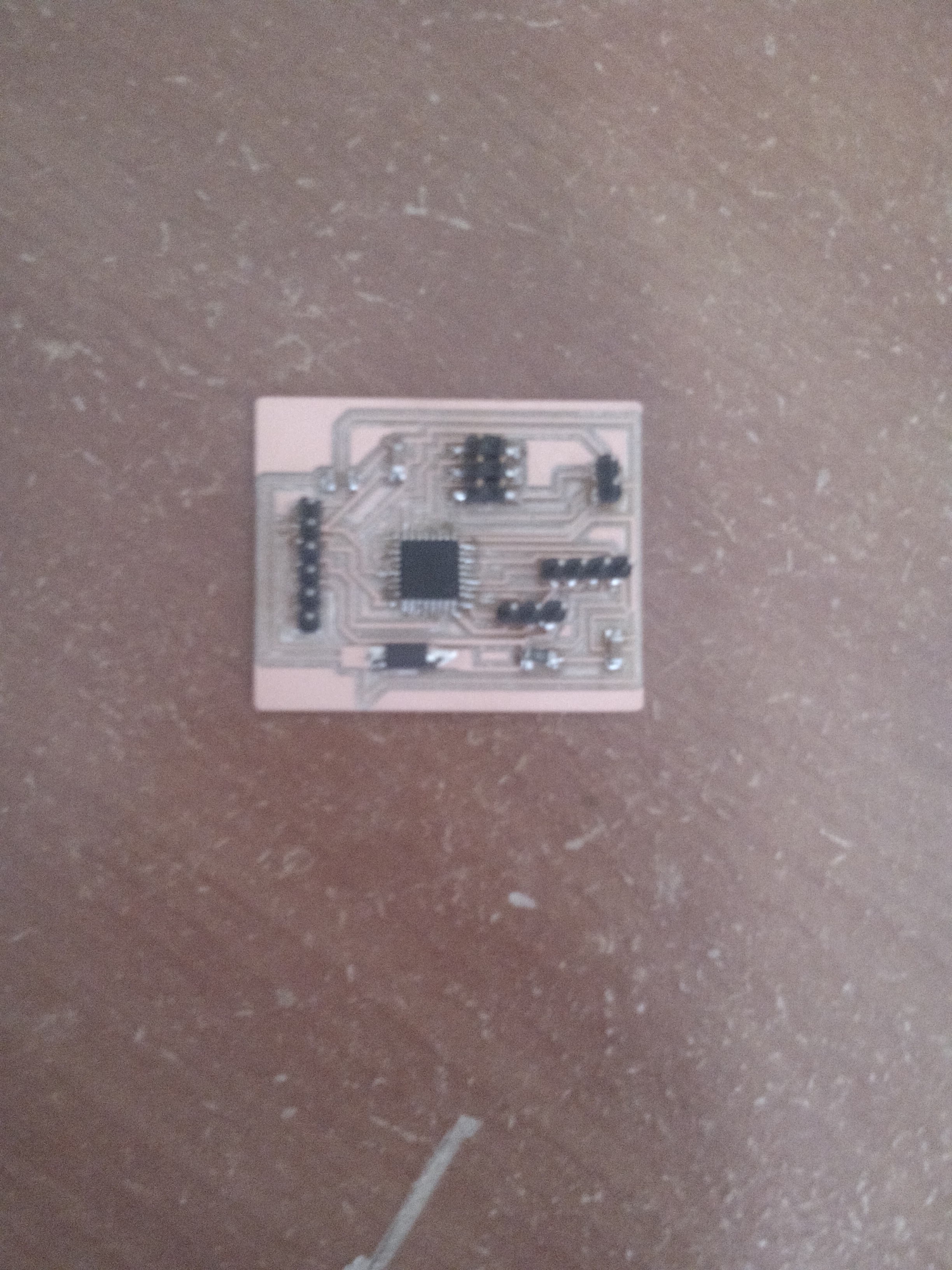
we can convert the schematics that are design in eagle into to board.
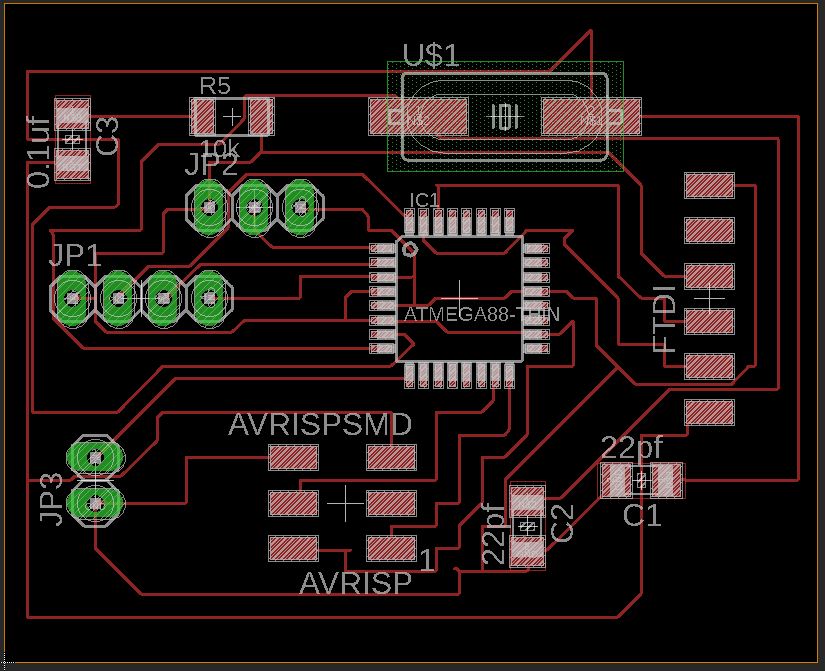
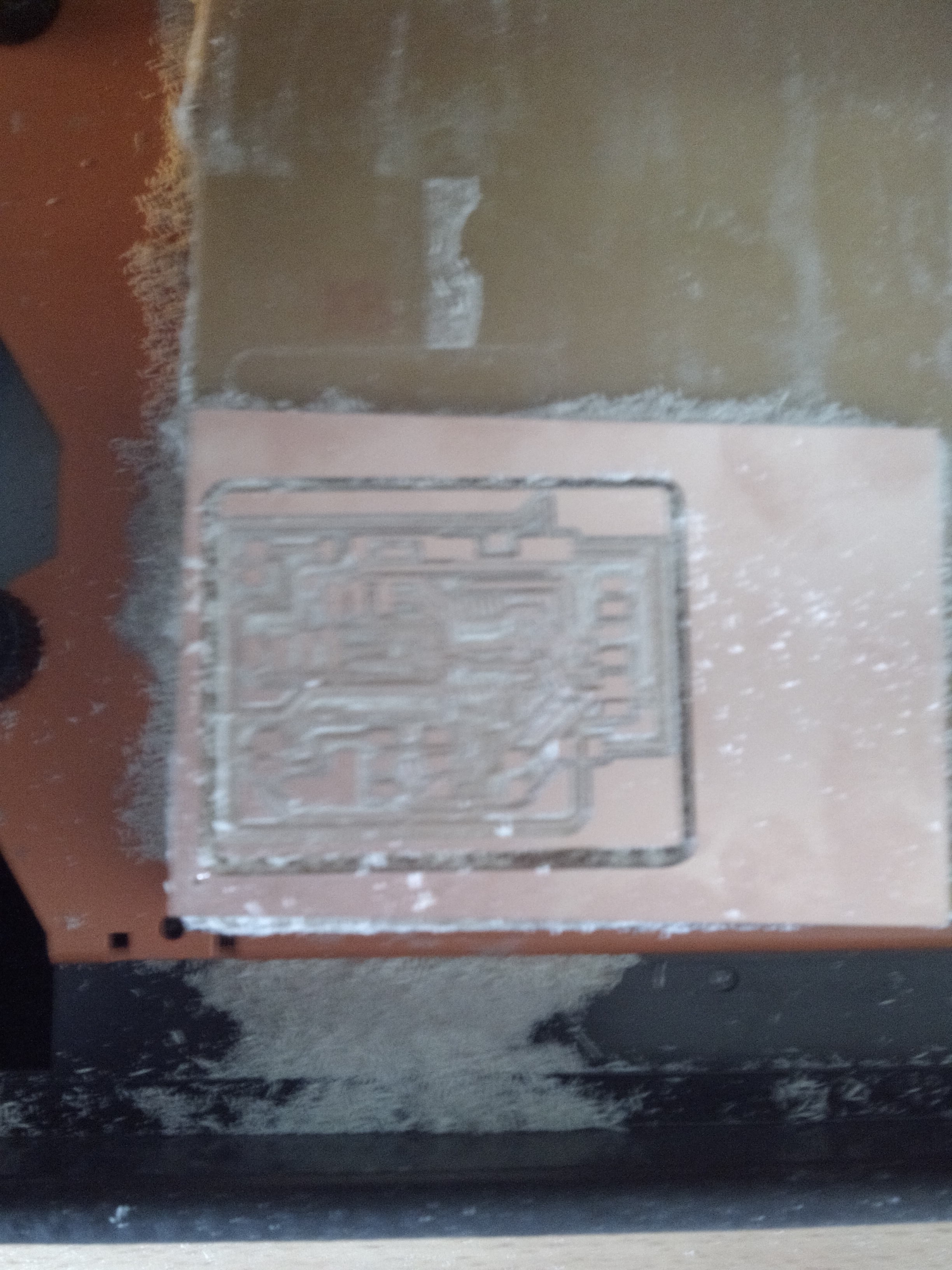
conevert the board into the png in trace.
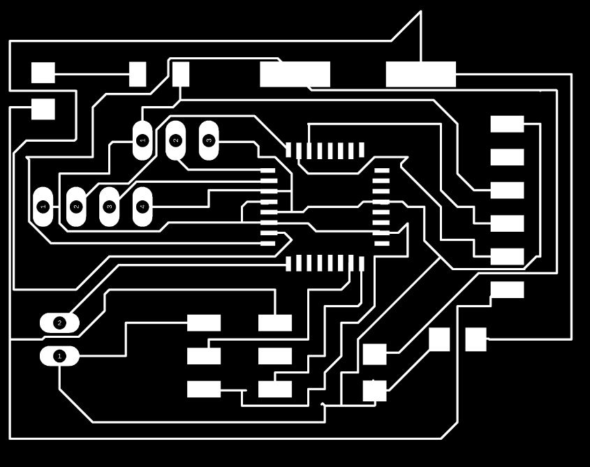
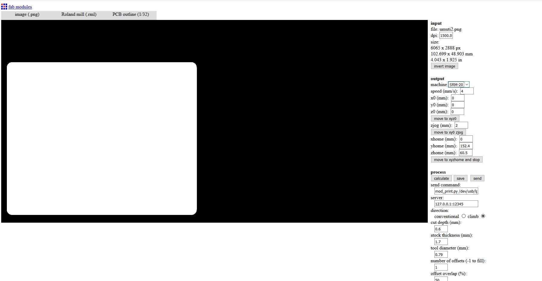
create the png of outline.

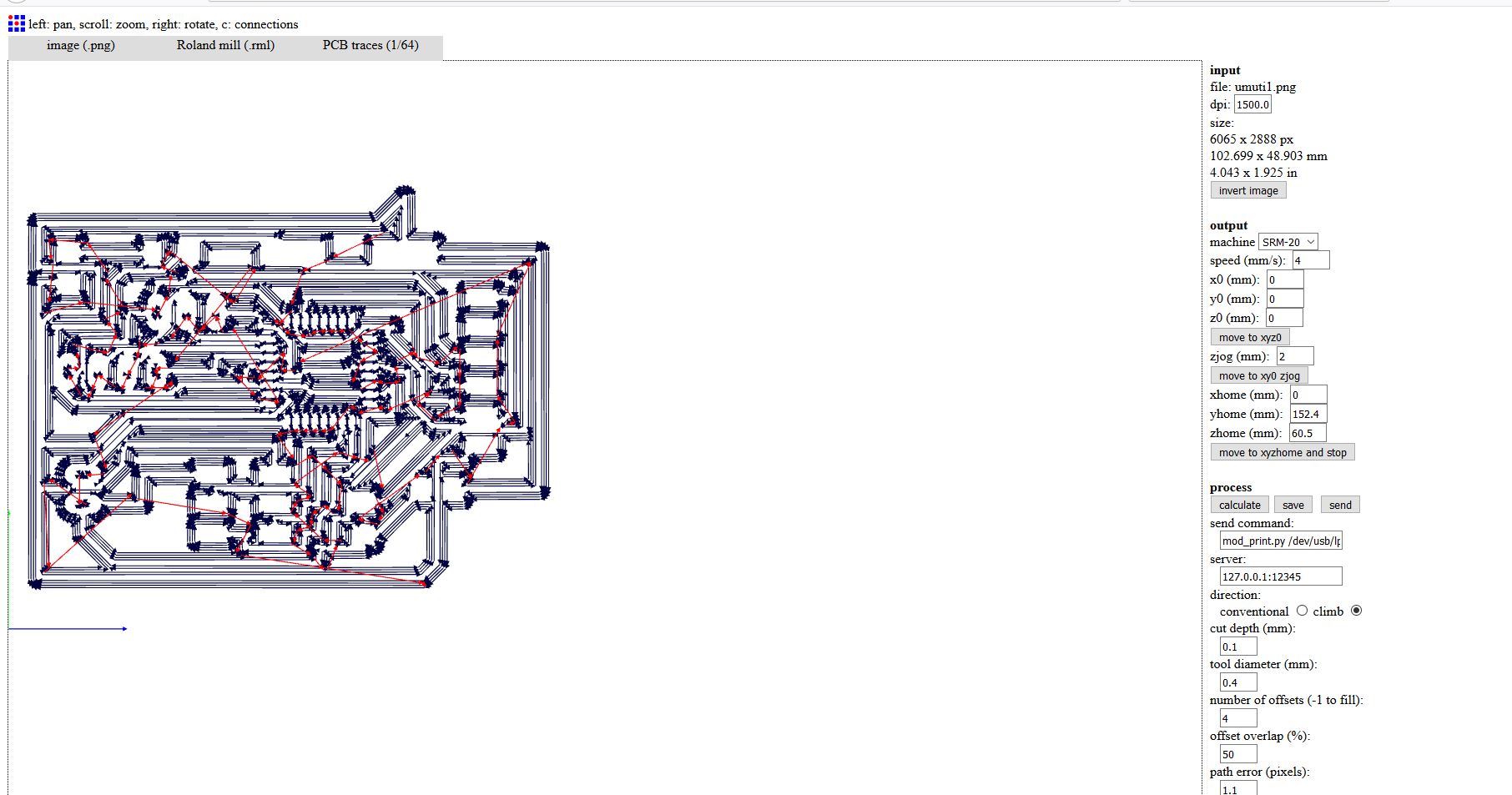
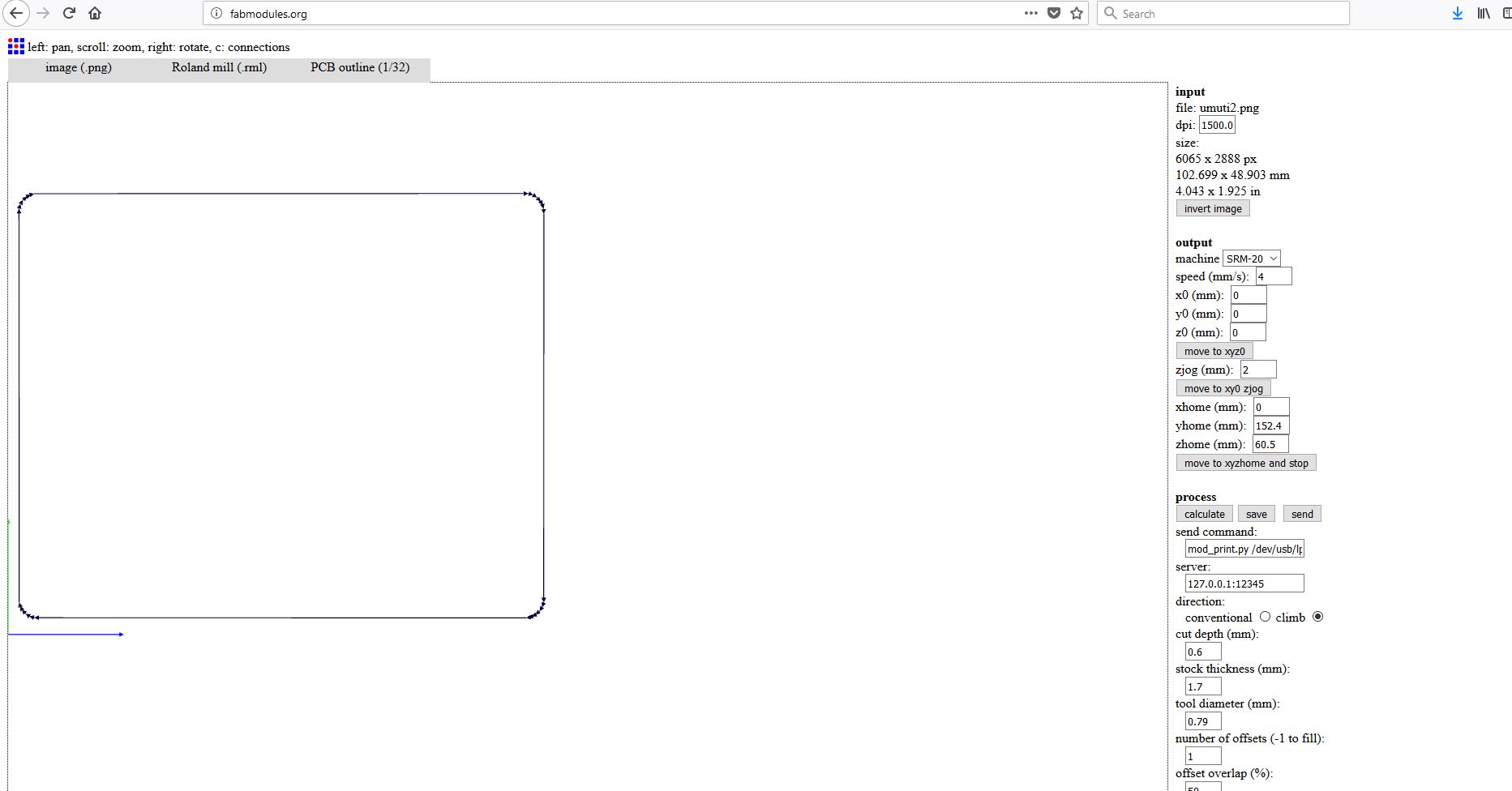
I have first converted my images from .png to .rml since its what the milling machine takes as input. I used fabmodules to convert fabISP images to rml. On Input format drop down I choosed image(.png), on output format I choosed Roland mill(.rml), and on process I choosed PCB traces(1/64). And continued selecting on machine I choosed SRM-20, other settings were made automatically then I clicked on Calculate button for converting it.
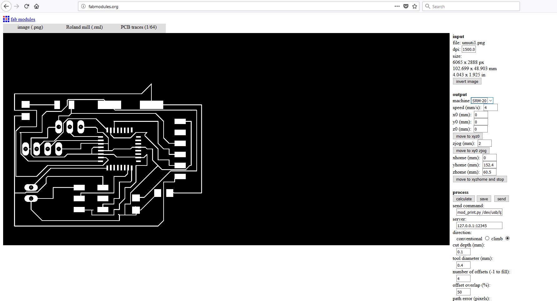
that schematics show some configuration by using fab modules
After calculation done on the image, the rml file is generated .
Now I have done the same thing on the edge cut file with some modification like on process I selected PCB outline(1/32) and on cut depth (mm): I entered 1.6 cause I want to cut through the board. .
After calculating the path for the tool the RML file is generated.
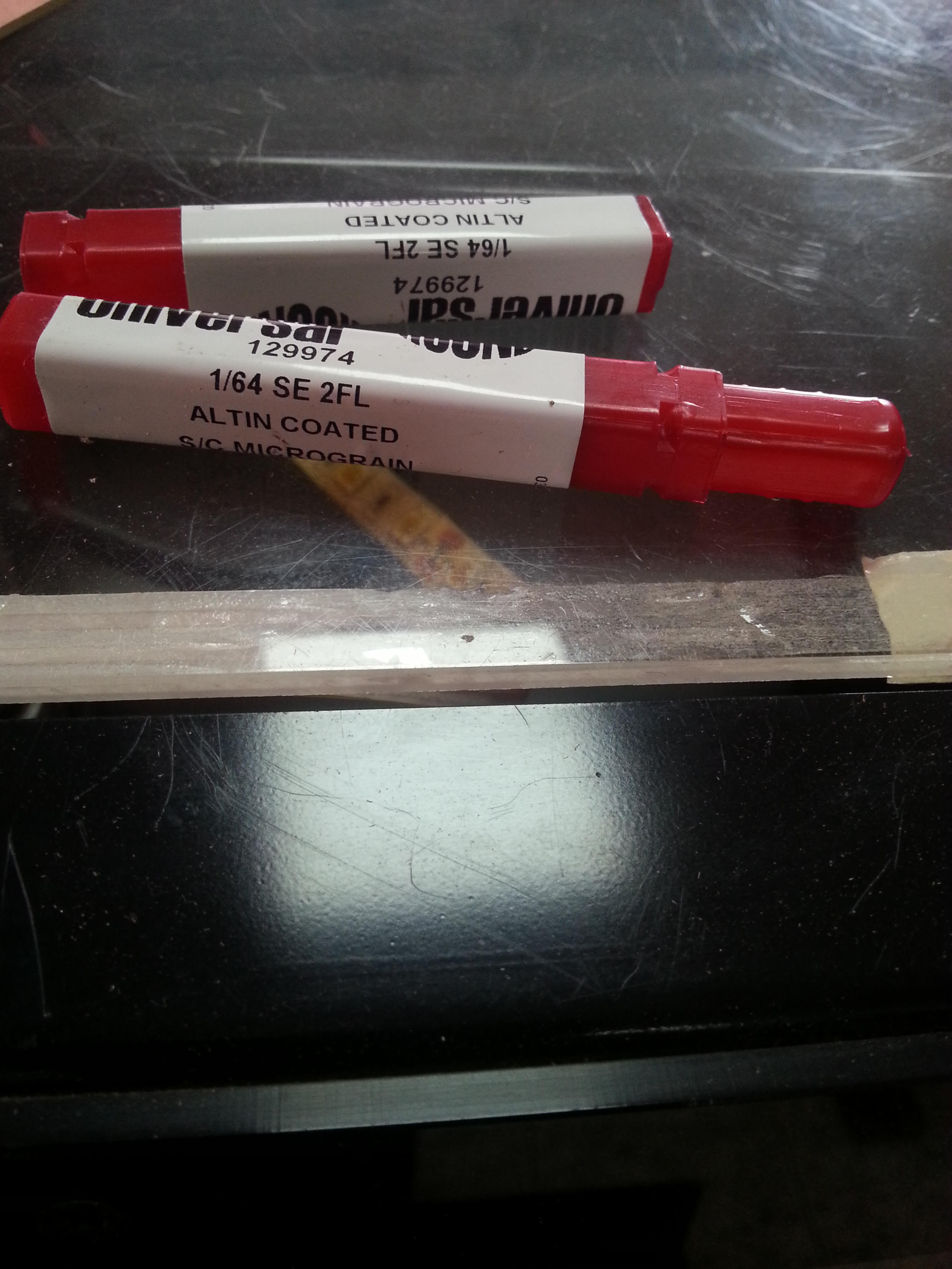
that are tools using to design the circuit in board.
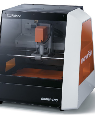
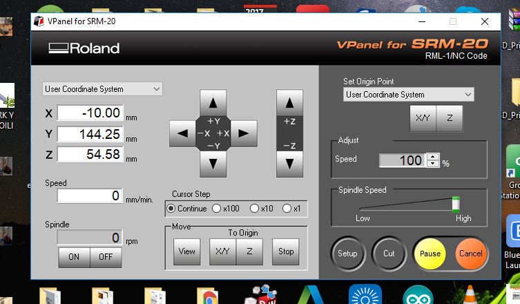
we use the software called v panel to set the machine.

Arduino IDE.
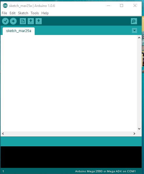
protocol in programming.
my coding how it communicate in my coding communicate by using class first we create the class in c++ and after we can call it.
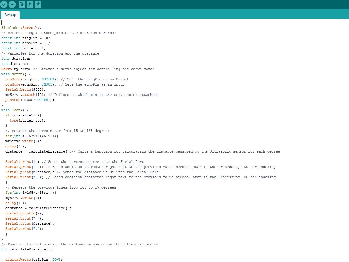
in that week we use one language the first is C++ .
All file used in that week we can Downloard here
that are the test.
– Up to 20 MIPS Throughput at 20 MHz.
– On-chip 2-cycle Multiplier.
• High Endurance Non-volatile Memory Segments.
– 4/8/16/32K Bytes of In-System Self-Programmable Flash progam memory(ATmega48PA/88PA/168PA/328P.
– 256/512/512/1K Bytes EEPROM (ATmega48PA/88PA/168PA/328P).
– 512/1K/1K/2K Bytes Internal SRAM (ATmega48PA/88PA/168PA/328P).
– Write/Erase Cycles: 10,000 Flash/100,000 EEPROM.
– Data retention: 20 years at 85°C/100 years at 25°C(1).
– Optional Boot Code Section with Independent Lock Bits In-System Programming by On-chip Boot Program True Read-While-Write Operation .
– Programming Lock for Software Security.
• Peripheral Features.
– Two 8-bit Timer/Counters with Separate Prescaler and Compare Mode.
– One 16-bit Timer/Counter with Separate Prescaler, Compare Mode, and Capture Mode.
– Real Time Counter with Separate Oscillator.
– Six PWM Channels.
– 8-channel 10-bit ADC in TQFP and QFN/MLF package Temperature Measurement.
– 6-channel 10-bit ADC in PDIP Package Temperature Measurement.
– Programmable Serial USART.
– Master/Slave SPI Serial Interface.
– Byte-oriented 2-wire Serial Interface (Philips I2 C compatible).
– Programmable Watchdog Timer with Separate On-chip Oscillator.
– On-chip Analog Comparator.
– Interrupt and Wake-up on Pin Change.
• Special Microcontroller Features.
– Power-on Reset and Programmable Brown-out Detection.
– Internal Calibrated Oscillator.
– External and Internal Interrupt Sources.
– Six Sleep Modes: Idle, ADC Noise Reduction, Power-save, Power-down, Standby, and Extended Standby.
• I/O and Packages.
– 23 Programmable I/O Lines.
– 28-pin PDIP, 32-lead TQFP, 28-pad QFN/MLF and 32-pad QFN/MLF .
• Operating Voltage:
– 1.8 - 5.5V for ATmega48PA/88PA/168PA/328P .
• Temperature Range:.
– -40°C to 85°C.
• Speed Grade:
– 0 - 20 MHz @ 1.8 - 5.5V.
• Low Power Consumption at 1 MHz, 1.8V, 25°C for ATmega48PA/88PA/168PA/328P:
– Active Mode: 0.2 mA
– Power-down Mode: 0.1 µA
– Power-save Mode: 0.75 µA (Including 32 kHz RTC)
pin out of microcontroller
you can downloard the datasheet of Atmega 328p click here
in that embedded programming i can programme my controller of my project i can begin our circuit.
we can begin to skech in software called eagle
we can convert the schematics that are design in eagle into to board.
conevert the board into the png in trace.
create the png of outline.
I have first converted my images from .png to .rml since its what the milling machine takes as input. I used fabmodules to convert fabISP images to rml. On Input format drop down I choosed image(.png), on output format I choosed Roland mill(.rml), and on process I choosed PCB traces(1/64). And continued selecting on machine I choosed SRM-20, other settings were made automatically then I clicked on Calculate button for converting it.
that schematics show some configuration by using fab modules
After calculation done on the image, the rml file is generated .
Now I have done the same thing on the edge cut file with some modification like on process I selected PCB outline(1/32) and on cut depth (mm): I entered 1.6 cause I want to cut through the board. .
After calculating the path for the tool the RML file is generated.
that are tools using to design the circuit in board.
we use the software called v panel to set the machine.
Arduino IDE.
protocol in programming.
my coding how it communicate in my coding communicate by using class first we create the class in c++ and after we can call it.
in that week we use one language the first is C++ .