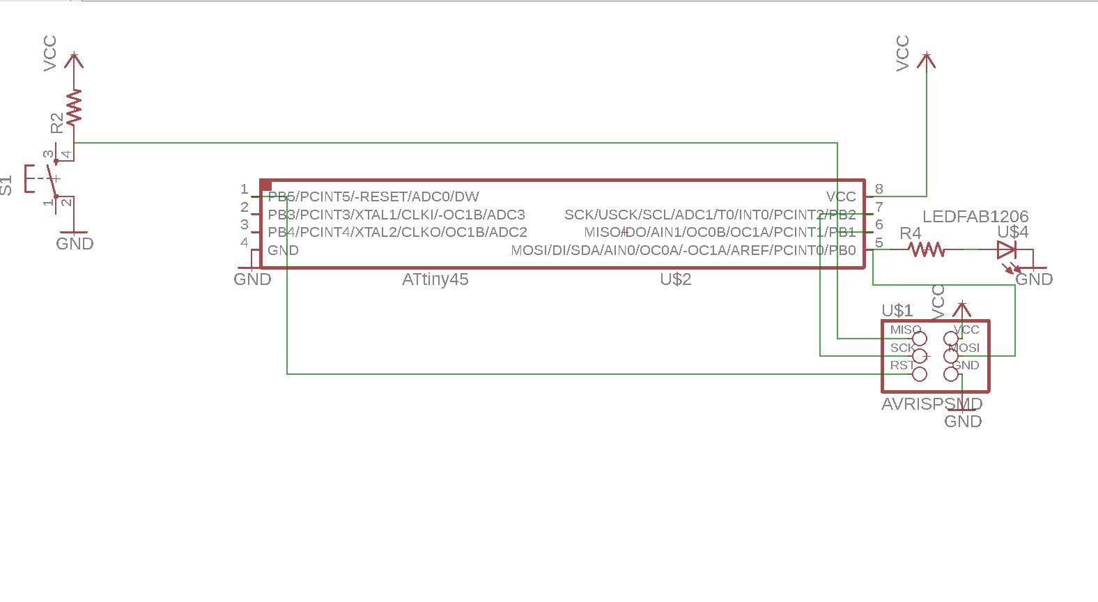
the second is to convert the schematics into the board.
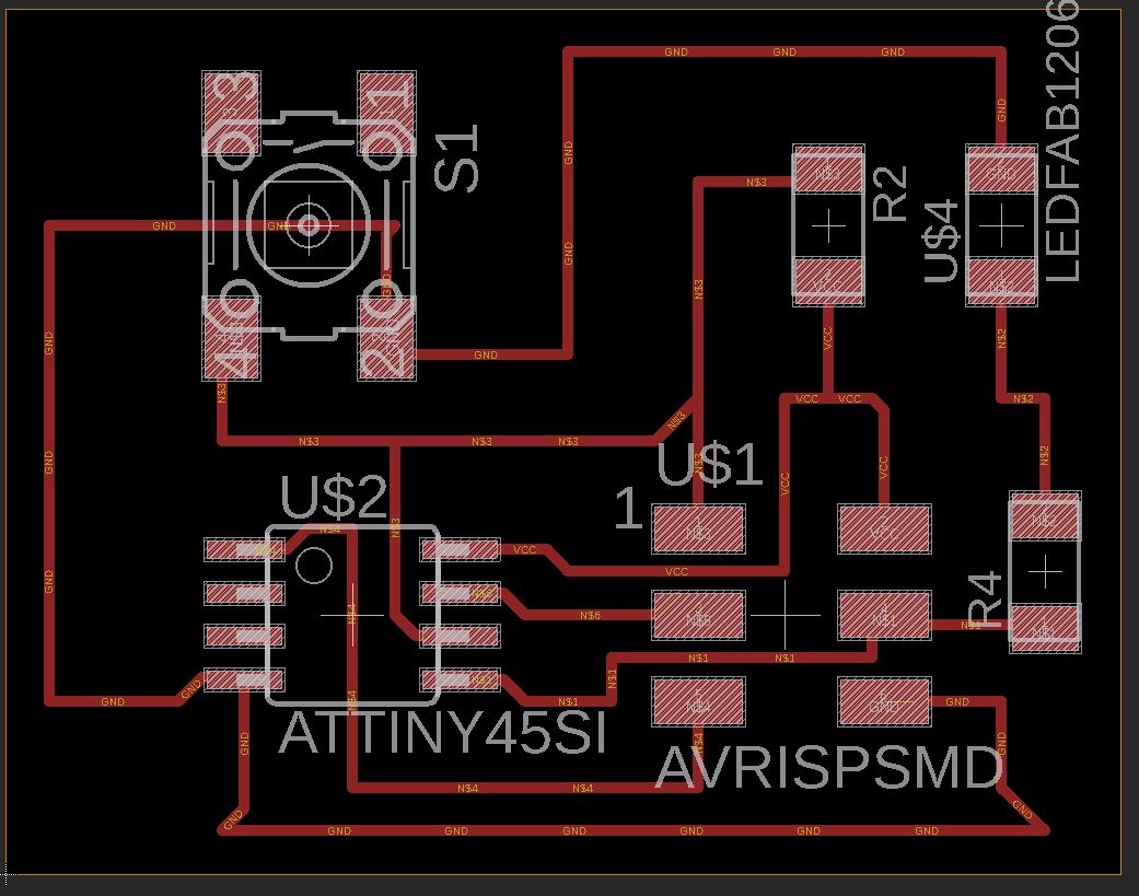
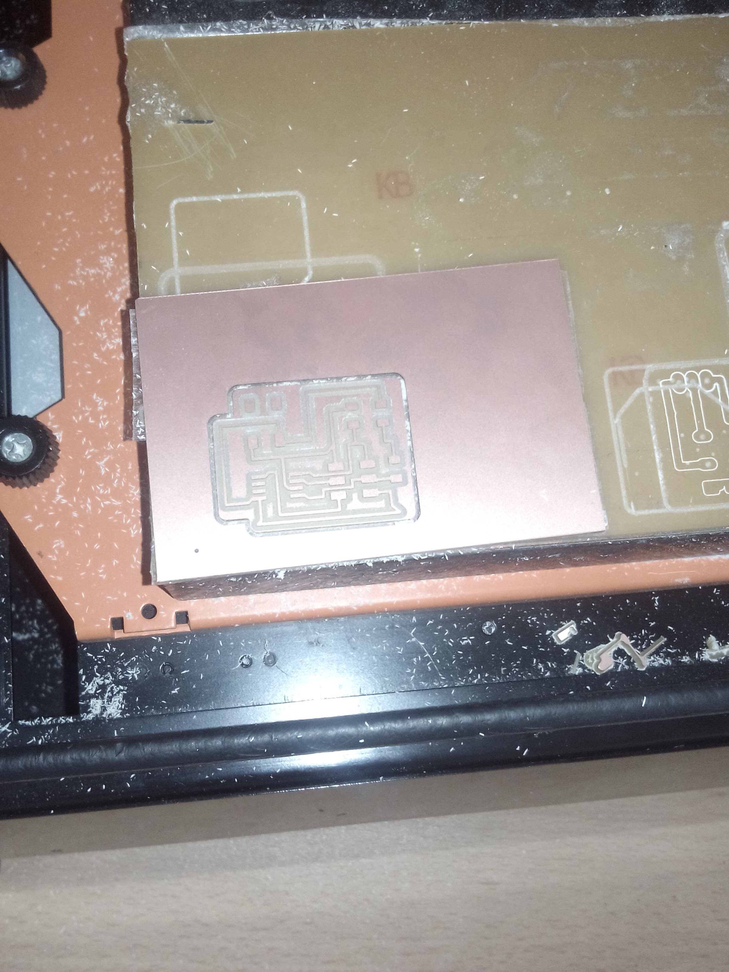
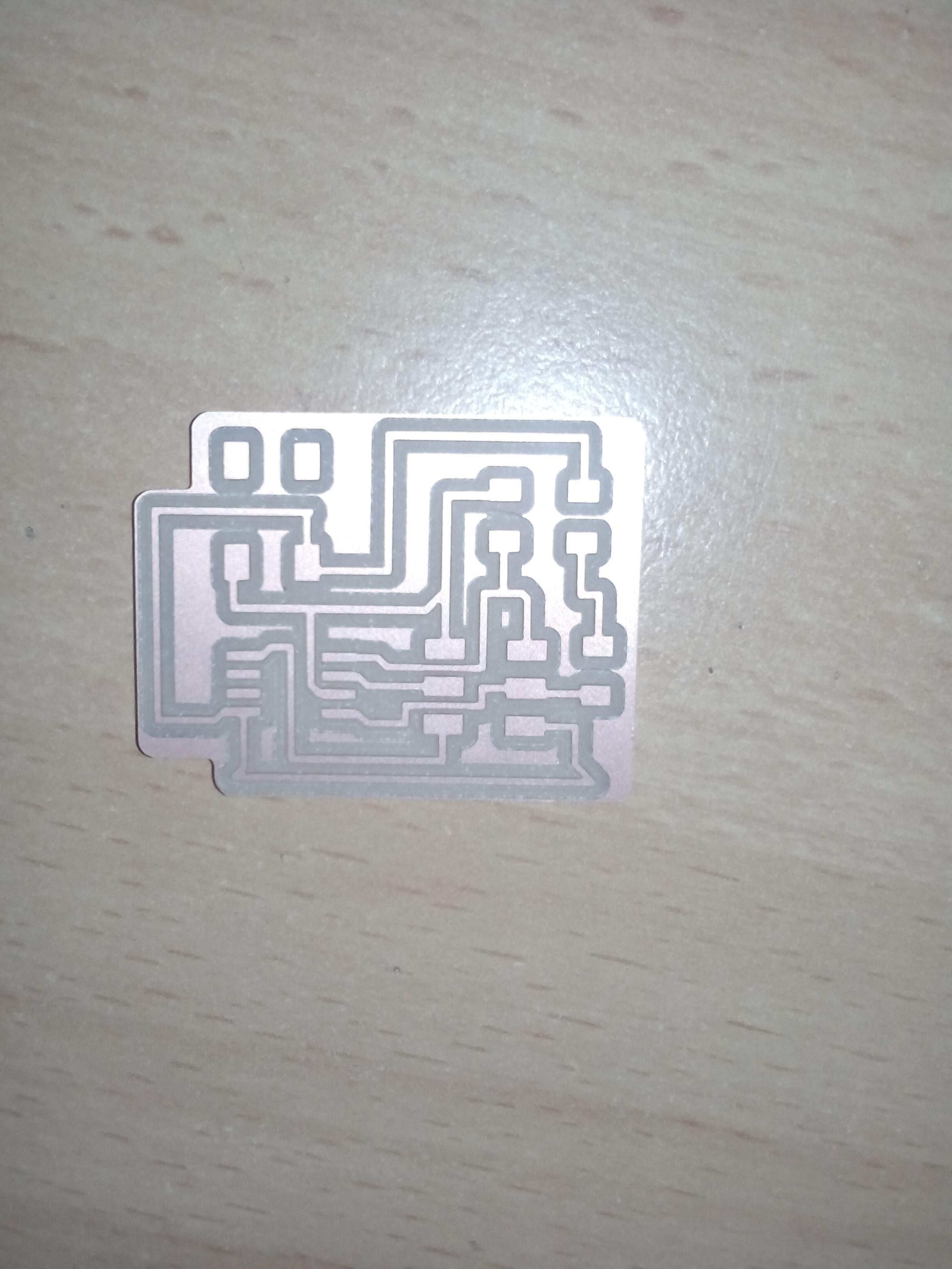
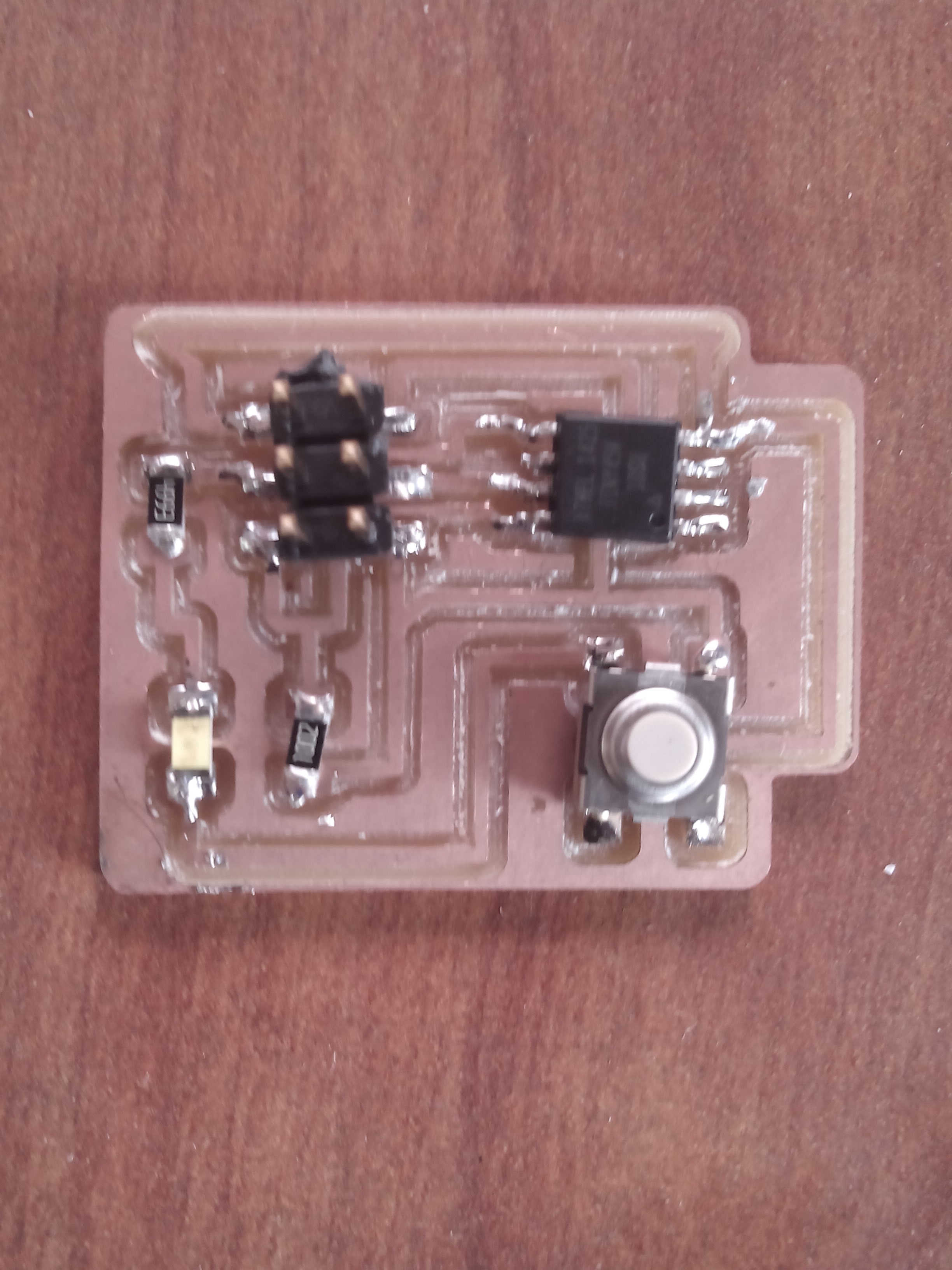
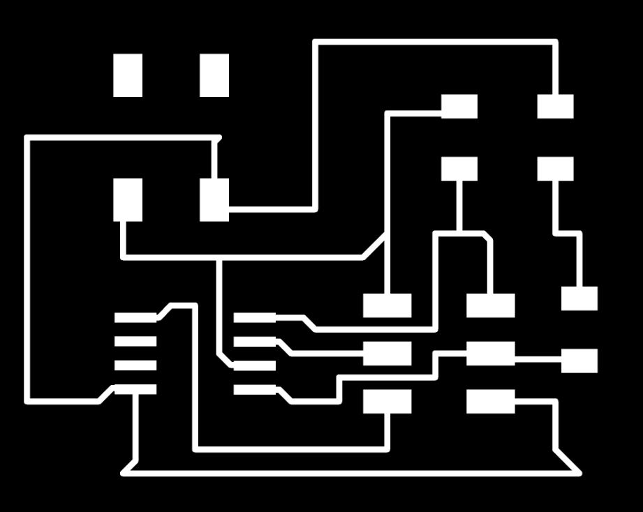
convert design of circuit that are design in board into the png Next step is to arrange the components on the board. For that there is an option "Switch to board". Click on that. Here we have to arrange the components as wee need to be in the PCB. After arranging, click on the Auto route option to route it. I forgot to take the scree shot od that. But i have the exprted monochrom png image I used to mill. See it here: .
and to create the PCB outline.

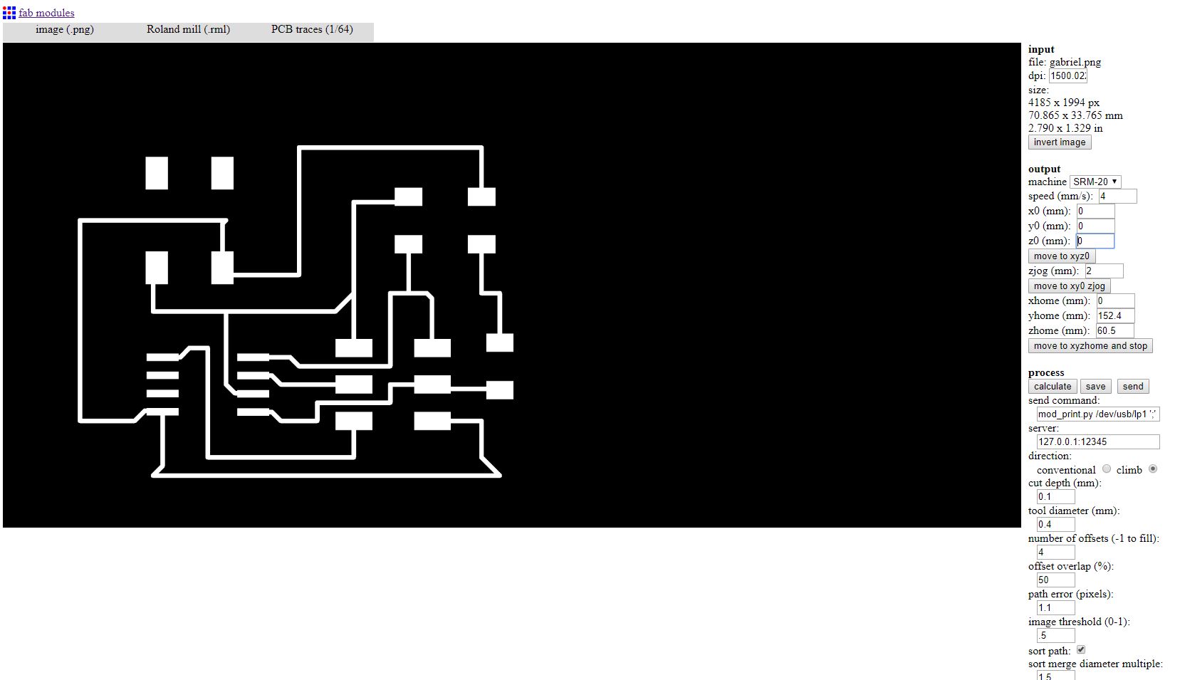
I have converted my images from .png to .rml since its what the milling machine takes as input. I used fabmodules to convert input circuit images to rml. On Input format drop down I choosed image(.png), on output format I choosed Roland mill(.rml), and on process I choosed PCB traces(1/64). And continued selecting on machine I choosed SRM-20, other settings were made automatically then I clicked on Calculate button for converting it. .
that schematics show some configuration by using fab modules.
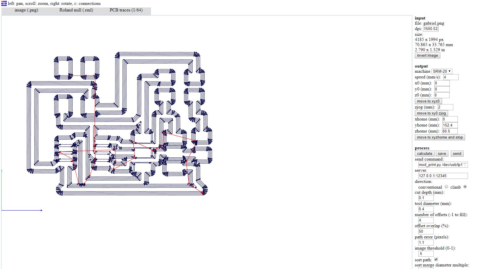
After calculation done on the image, the rml file is generated .
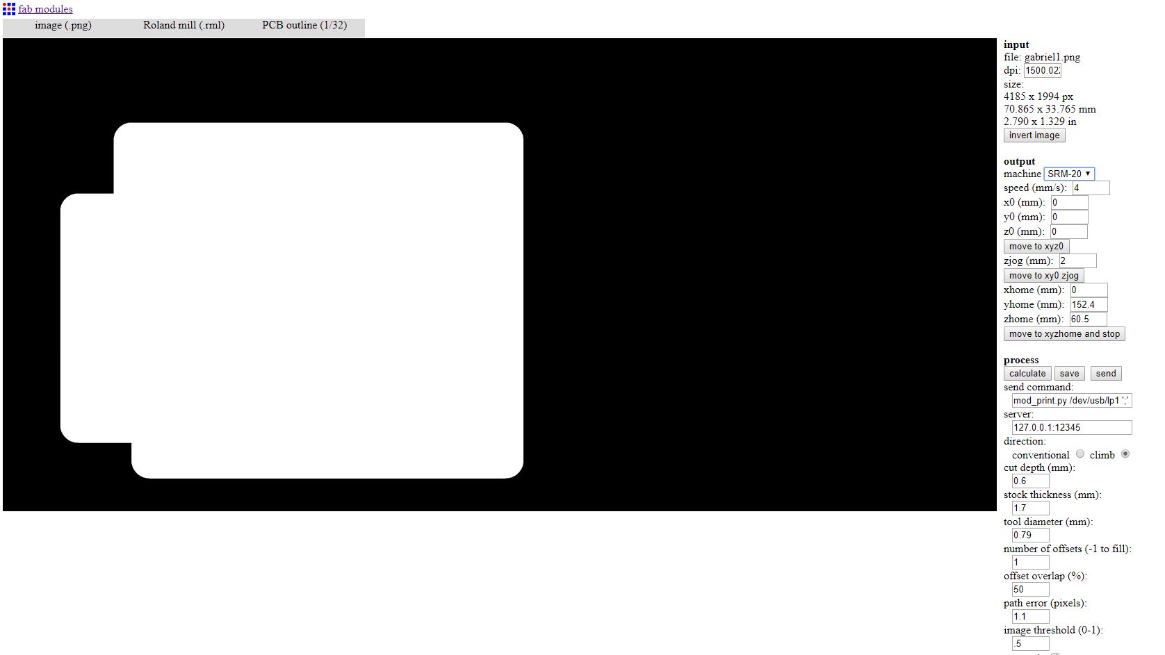
Now I have done the same thing on the edge cut file with some modification like on process I selected PCB outline(1/32) and on cut depth (mm): I entered 1.6 cause I want to cut through the board.
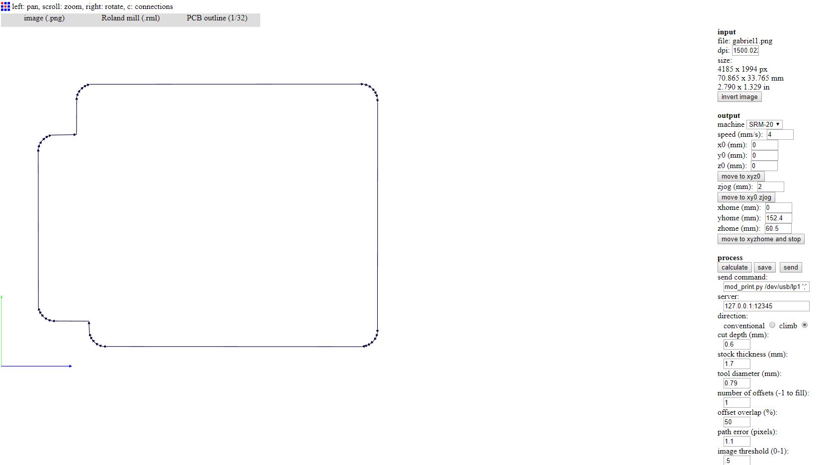
After calculating the path for the tool the RML file is generated.
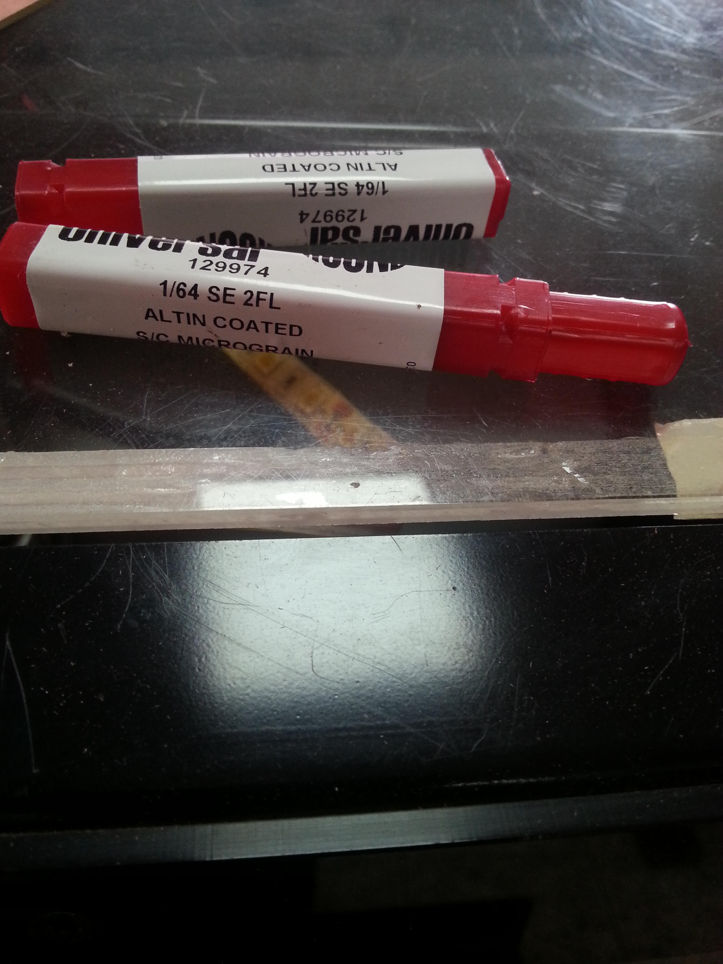
that are tools using to design the circuit in board.
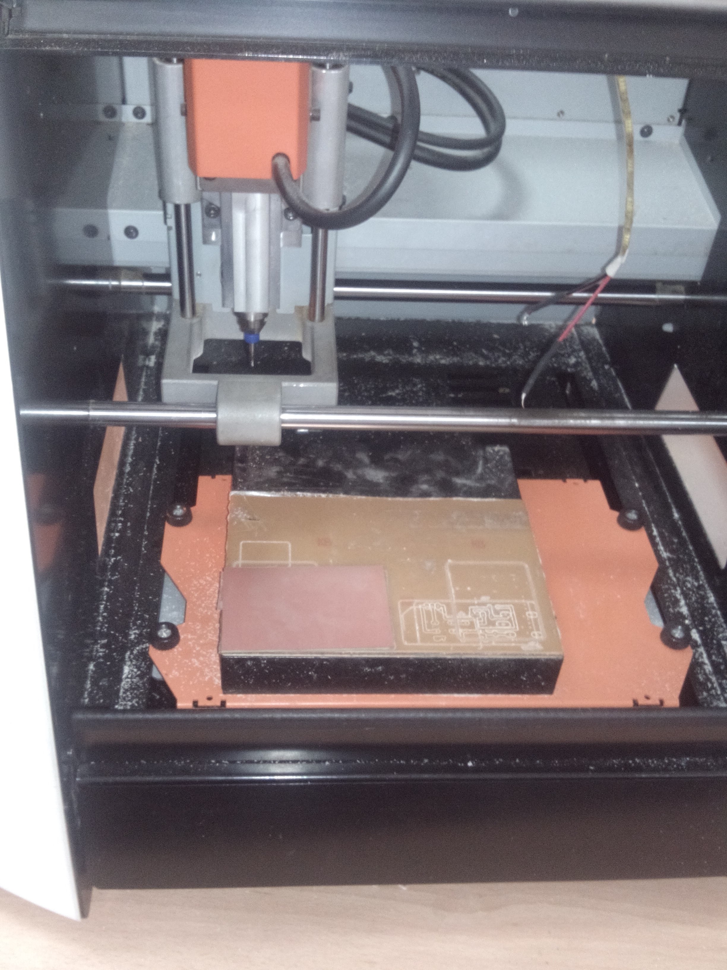
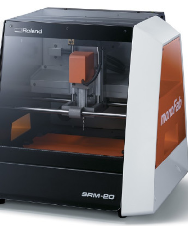
we use the software called v panel to set the machine.
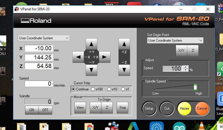
Now that I have fixed the board on the bed, I am ready to setup the machine and start milling.