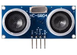
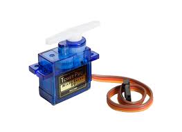
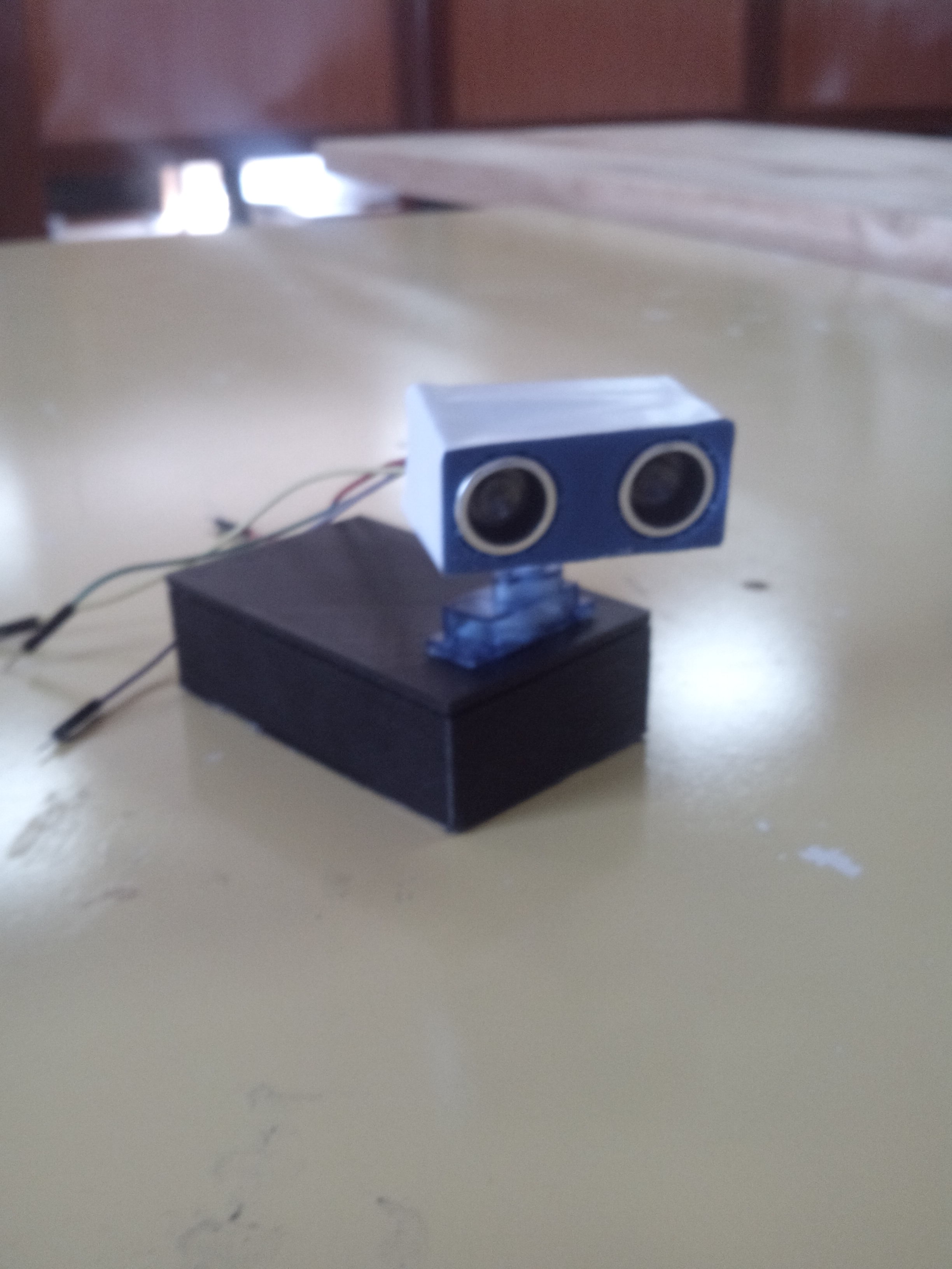
sevor motor
buzzer
In parts of programming
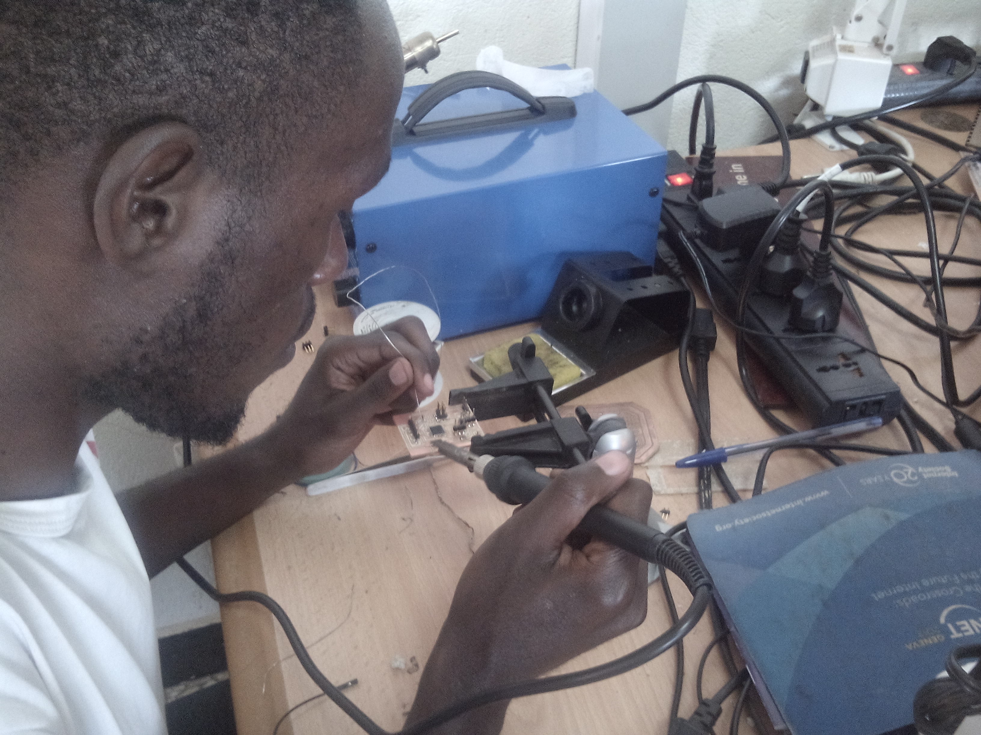
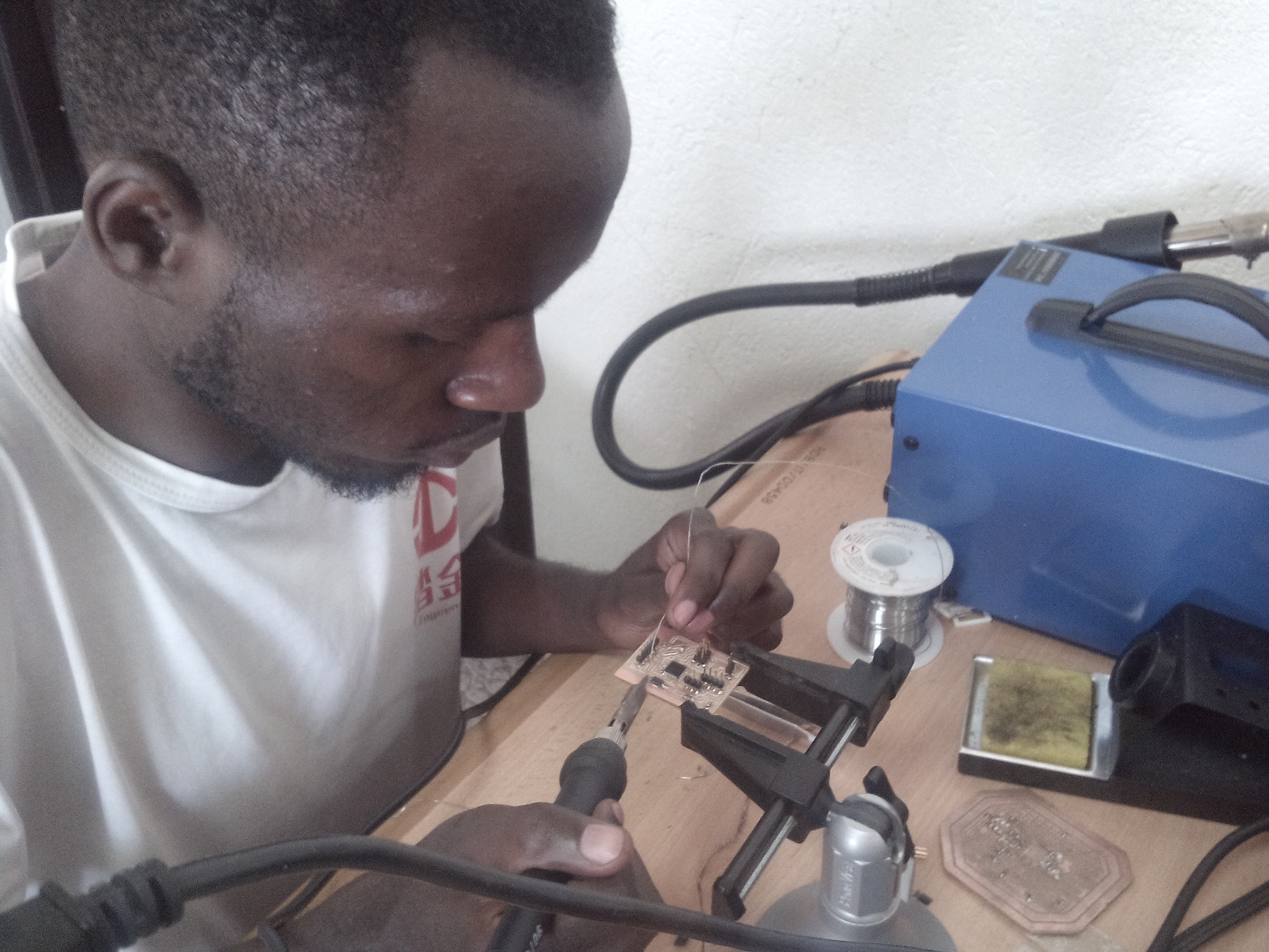
we can begin in programming of my board
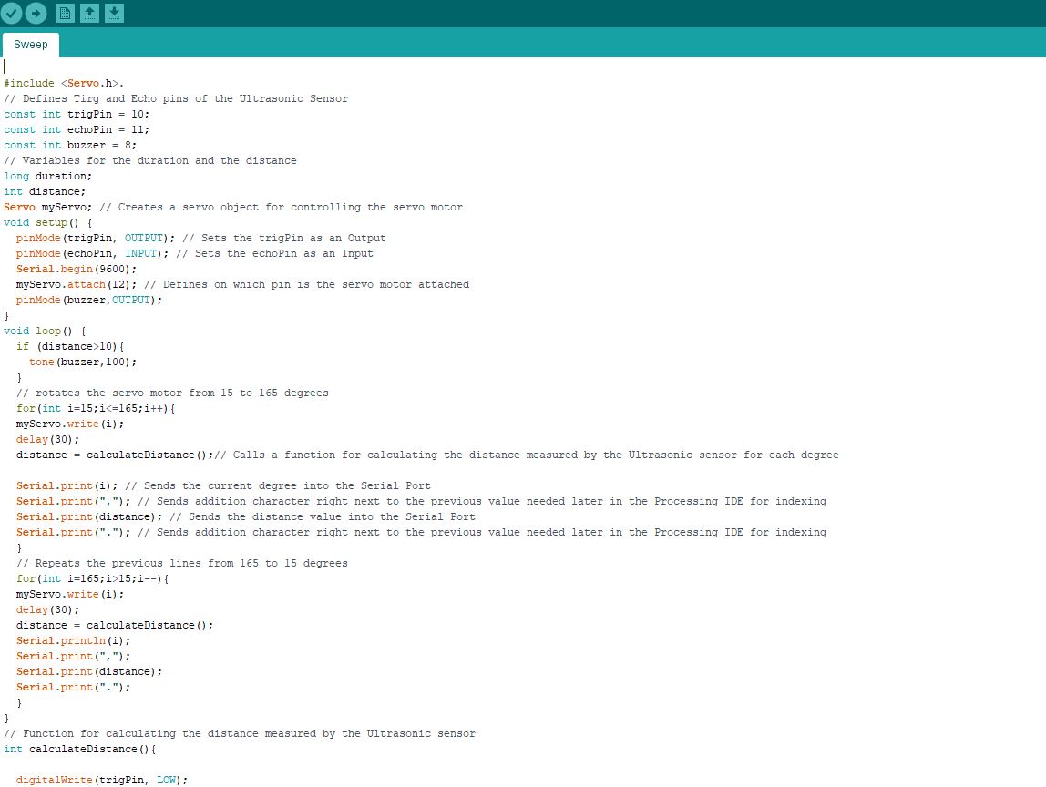
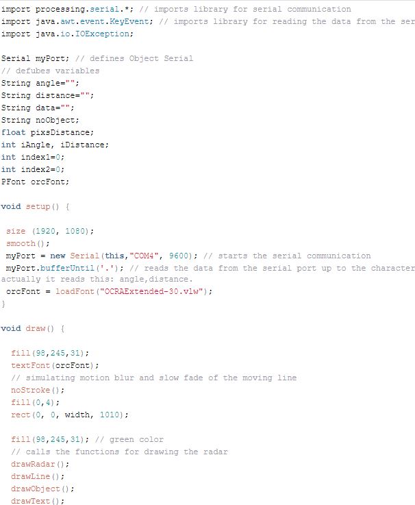
Arduino Source Code with description of each line of the code:
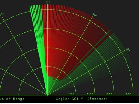
Now we will receive the values for the angle and the distance measured by the sensor from the Arduino Board into the Processing IDE using the SerialEvent() function which reads the data from the Serial Port and we will put the values of the angle and the distance into the variables iAngle and iDistance. These variable will be used for drawing the radar, the lines, the detected objects and some of the text. by using java code.
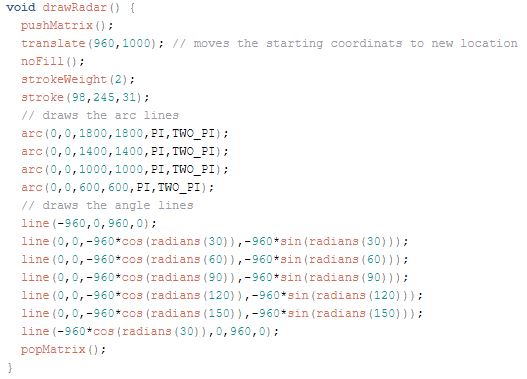
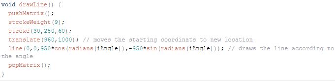
For drawing the line that is moving along the radar I made this function drawLine(). Its center of rotation is set with the translate() function and using the line() function in which the iAngle variable is used the line is redrawn for each degree.
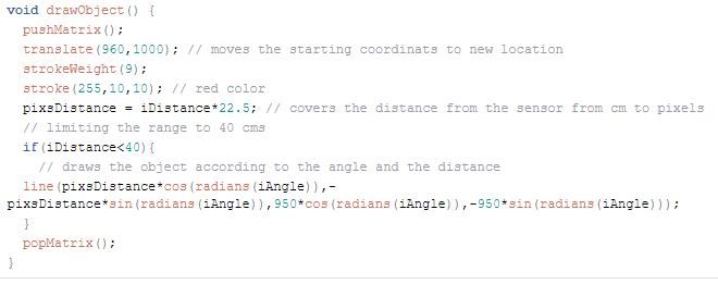
For drawing the detected objects I made this drawObject() function. It gets the distance from ultrasonic sensor, transforms it into pixels and in combination with the angle of the sensor draws the object on the radar.
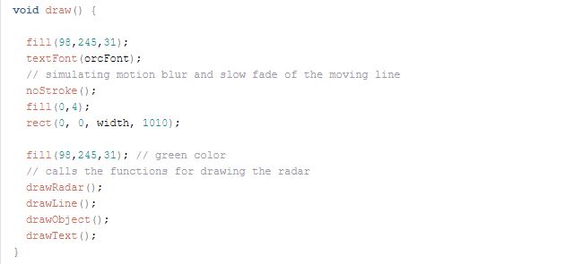
All of these functions are called in the main draw() function which repeats all the time and draws the screen. Also here I am using this fill() function with 2 parameters for simulating motion blur and slow fade of the moving line.
that are the application interface that are created
that is the complete Processing Source Code of the Arduino Radar:
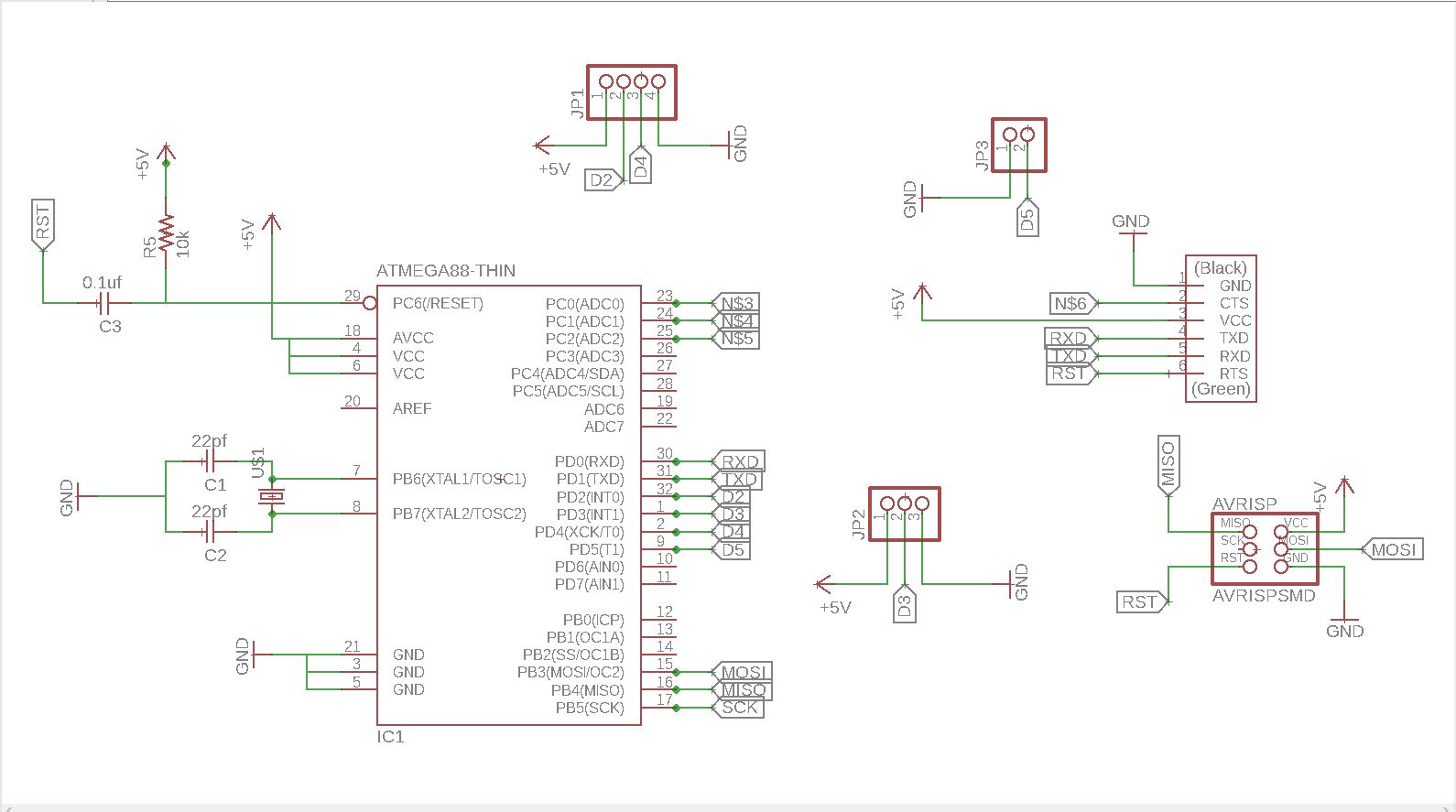
in part of electronics
we can begin to skech in software called eagle
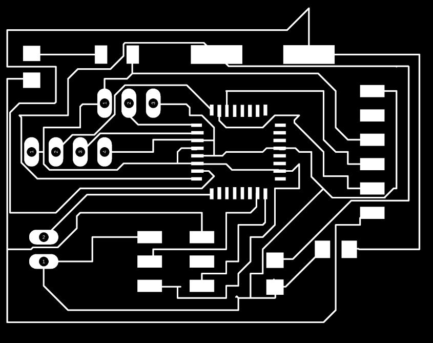
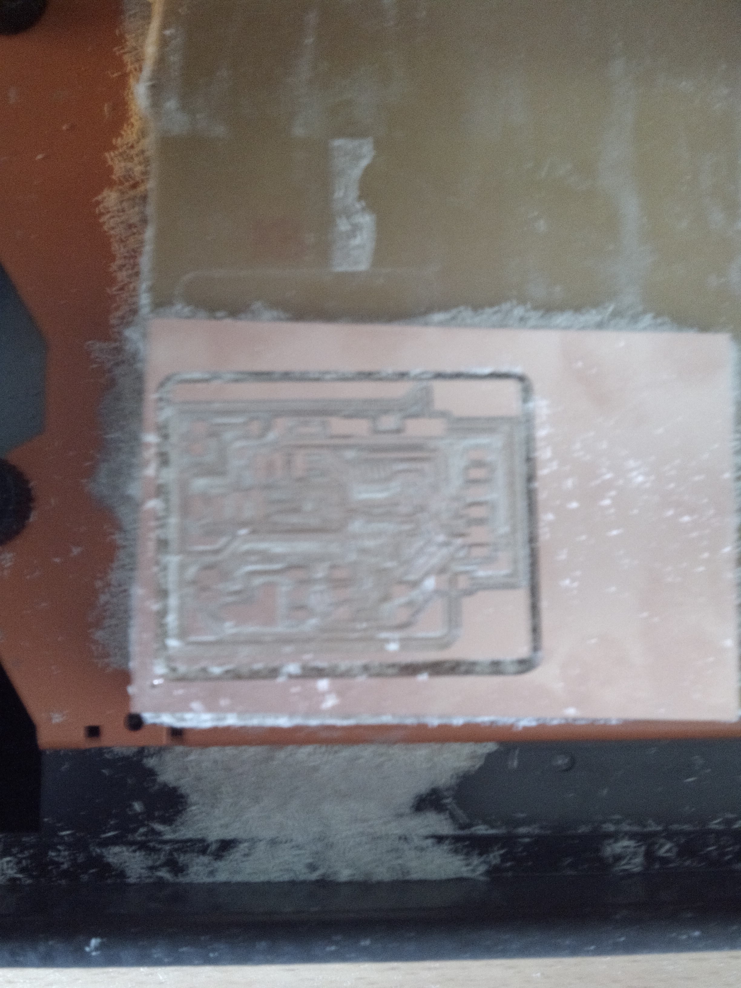
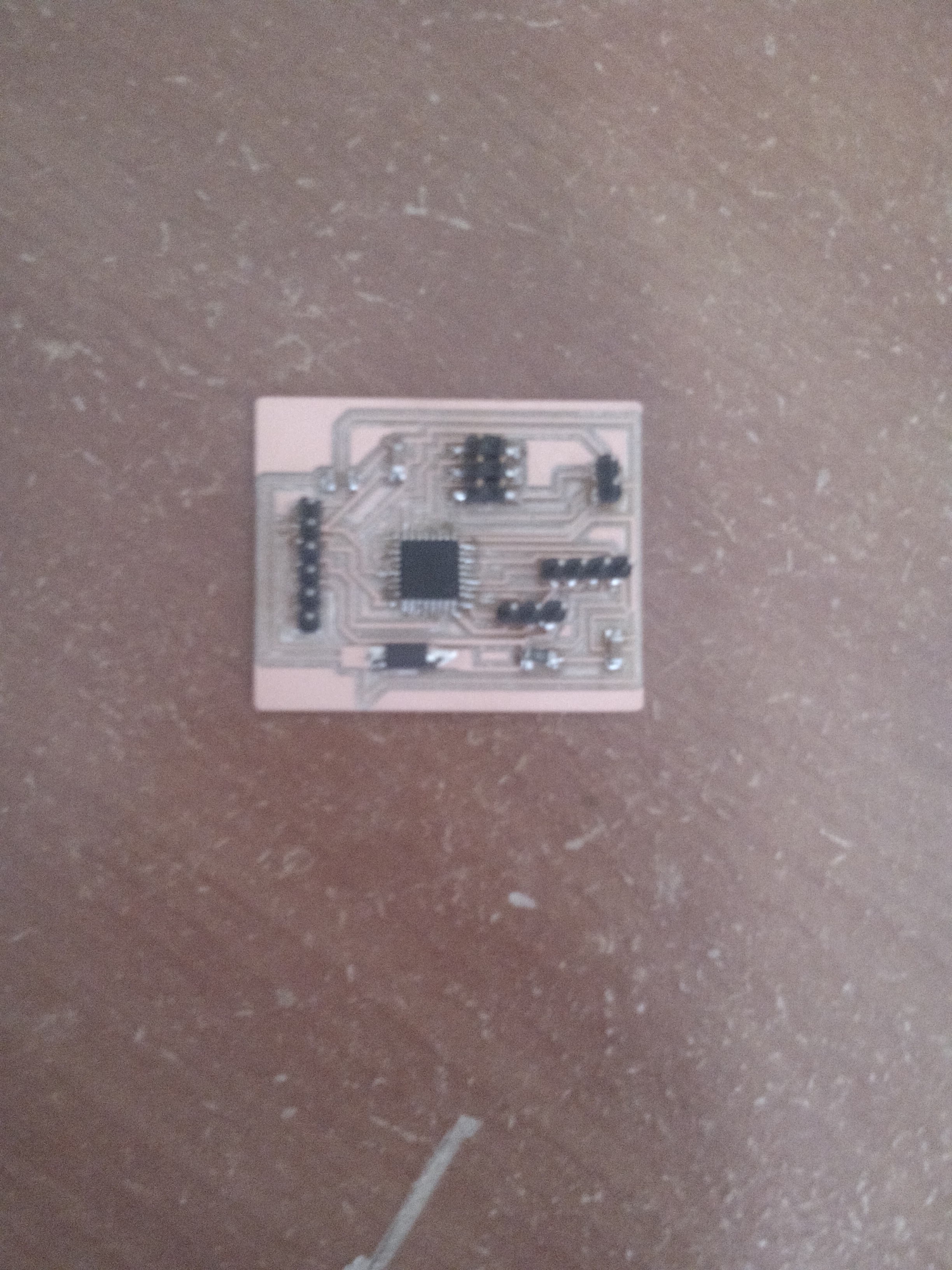
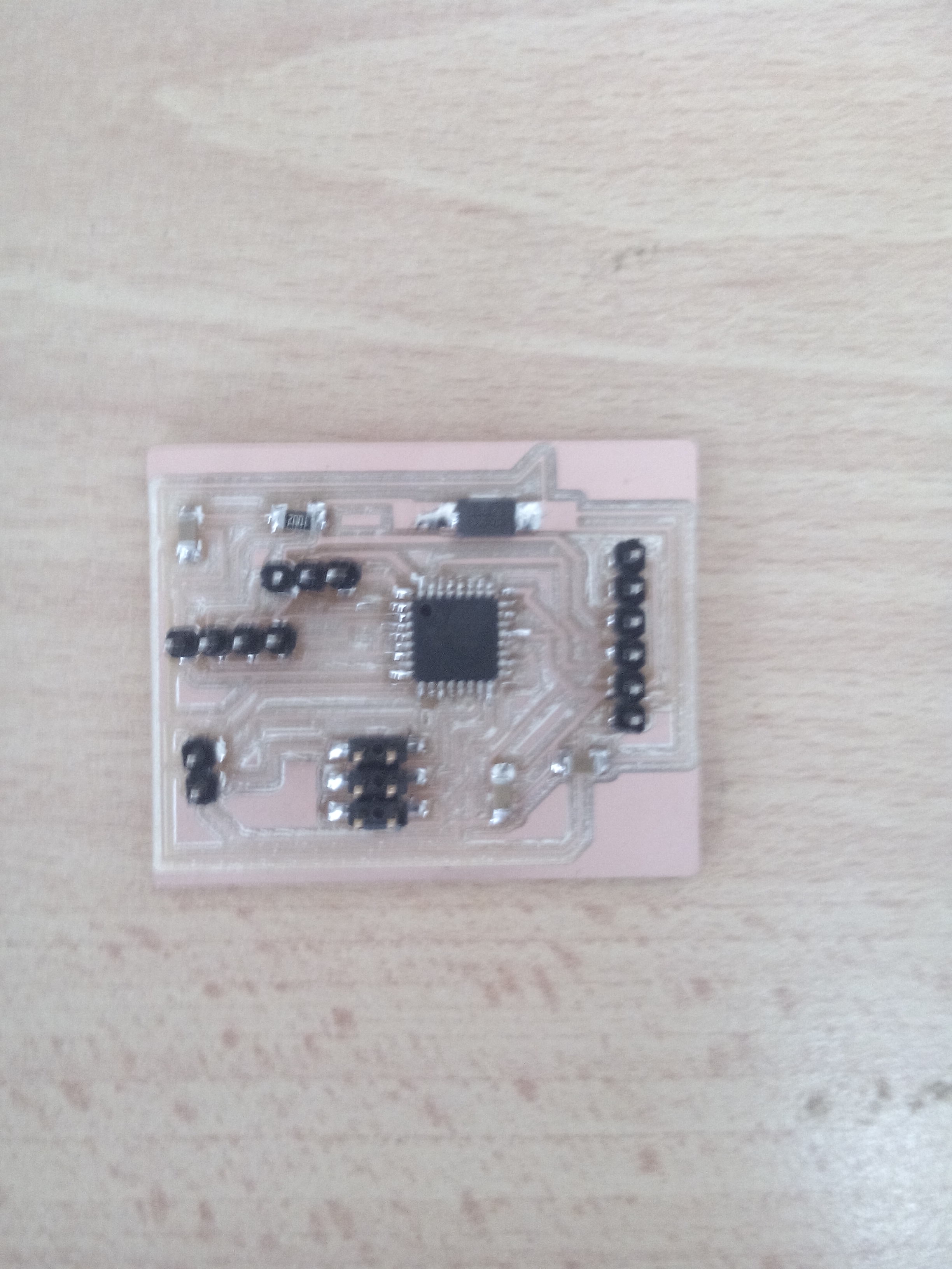
we can convert the schematics that are design in eagle into to board.
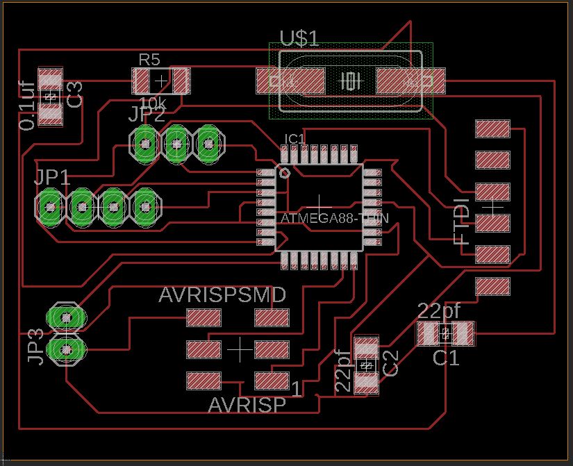
conevert the board into the png in trace.
create the png of outline.

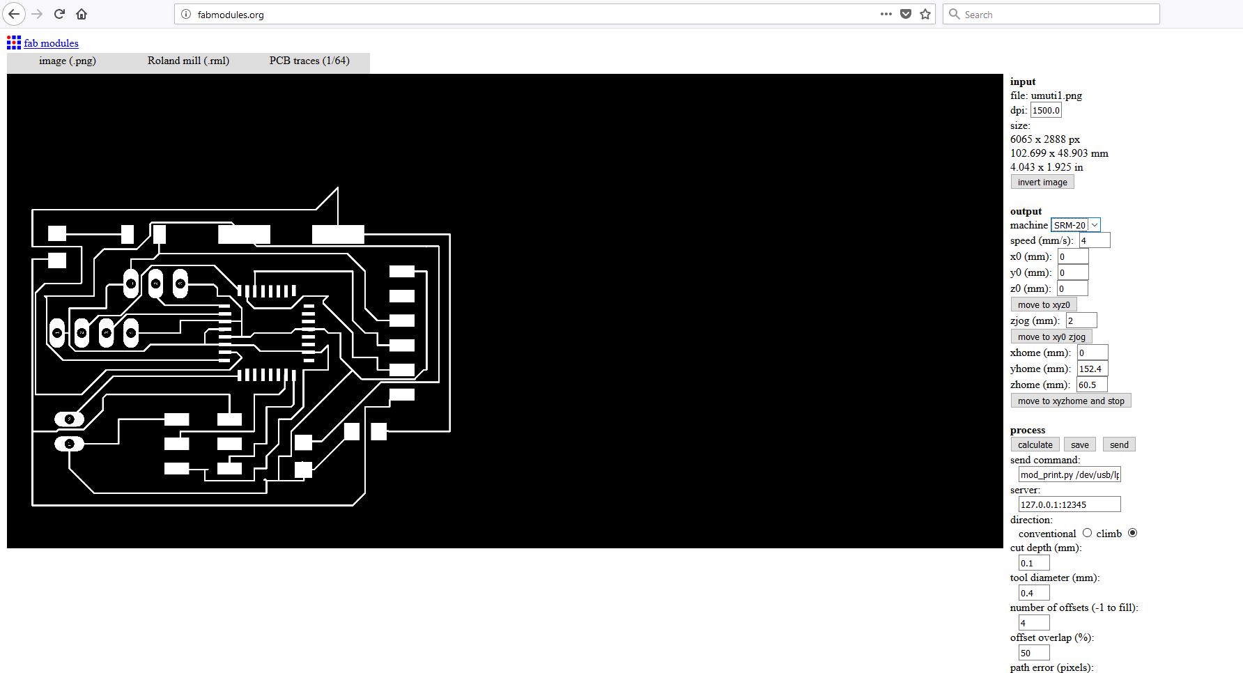
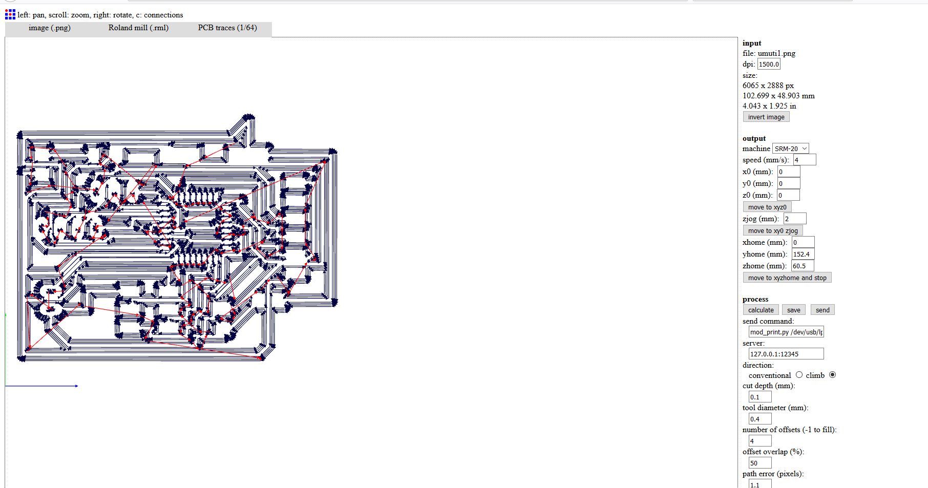
I have first converted my images from .png to .rml since its what the milling machine takes as input. I used fabmodules to convert fabISP images to rml. On Input format drop down I choosed image(.png), on output format I choosed Roland mill(.rml), and on process I choosed PCB traces(1/64). And continued selecting on machine I choosed SRM-20, other settings were made automatically then I clicked on Calculate button for converting it.
that schematics show some configuration by using fab modules
After calculation done on the image, the rml file is generated .
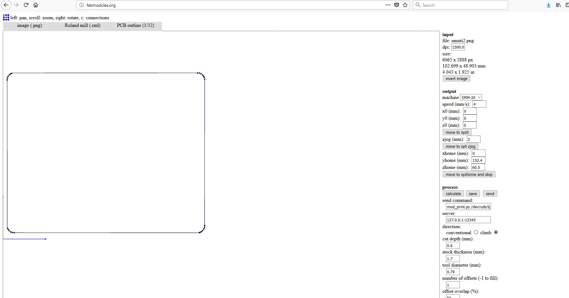
Now I have done the same thing on the edge cut file with some modification like on process I selected PCB outline(1/32) and on cut depth (mm): I entered 1.6 cause I want to cut through the board. .
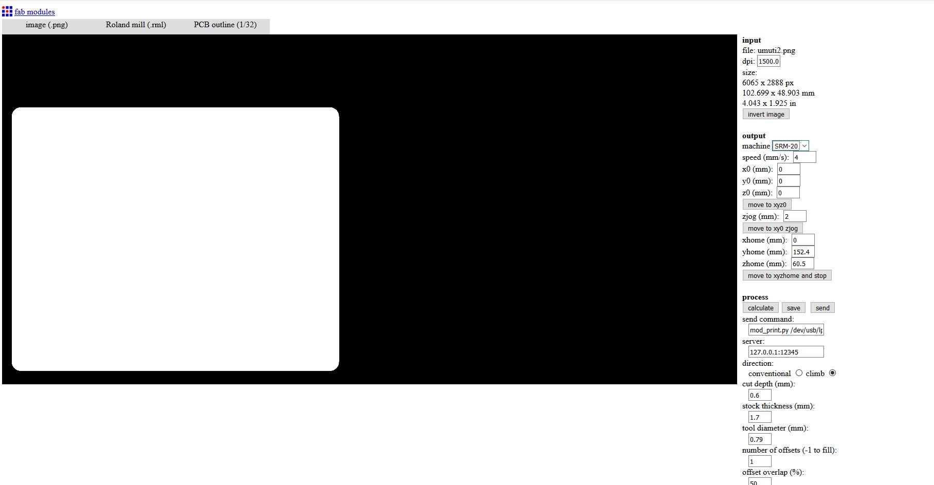
After calculating the path for the tool the RML file is generated.
the final project.
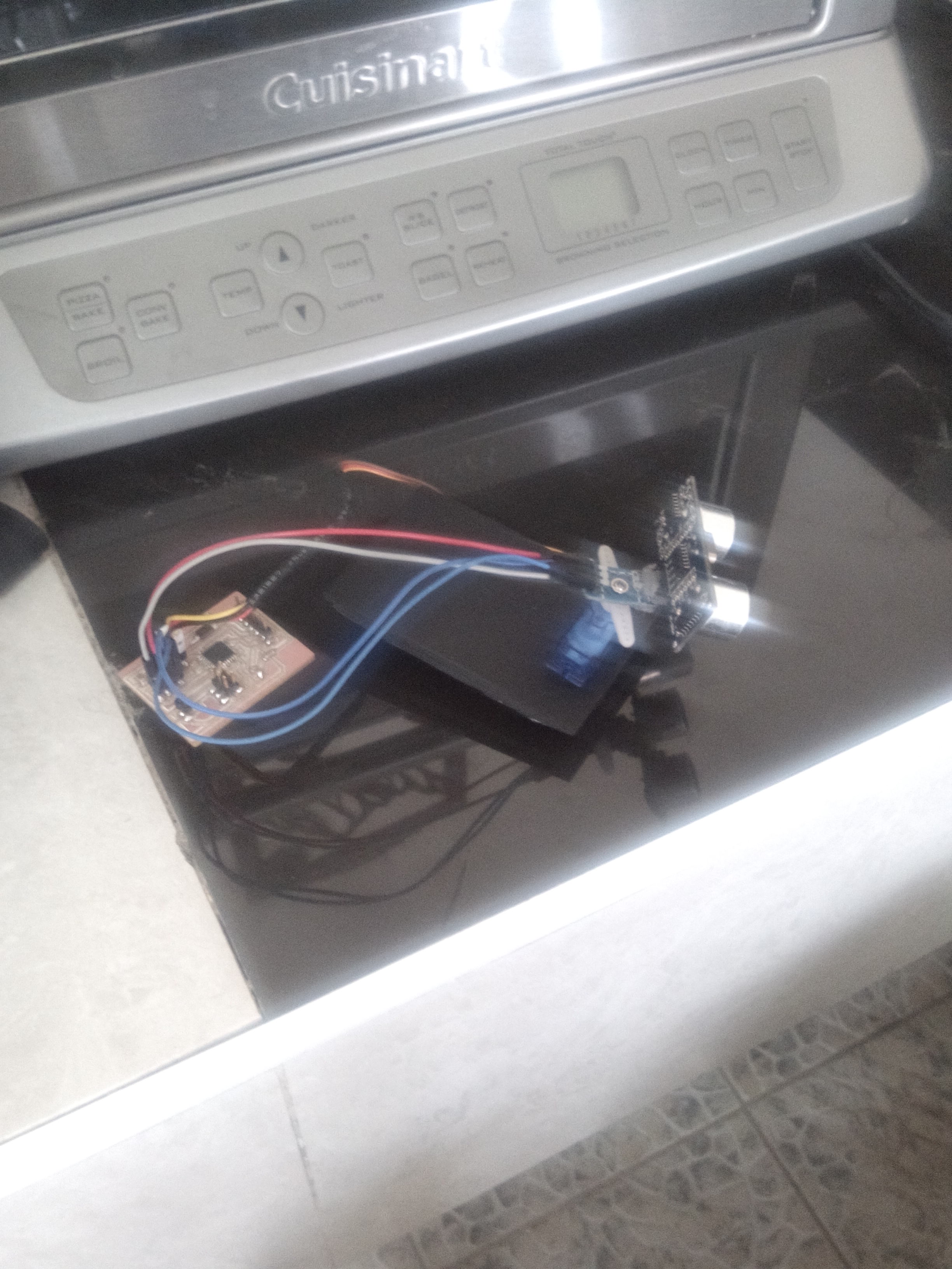
a bout my project we can commnicate the my owner board that are design and the pc by controlling my owner board by using pc machine
All file used in that week we can Downloard here
a bout the tutorial of network protocal click here