Assignment: Design and build a wired &/or wireless network connecting at least two processors.
 I made an LCD board, with a 6 pin header instead of the 4 pin one, so it could be used as a networking node.
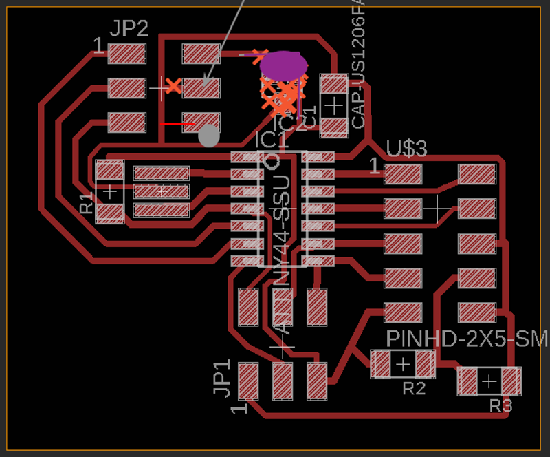
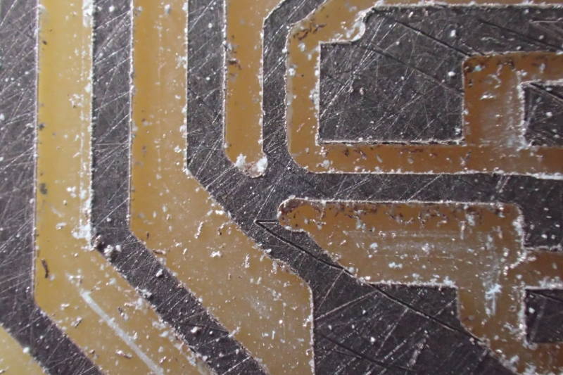 There was one area where the mill could not get through.
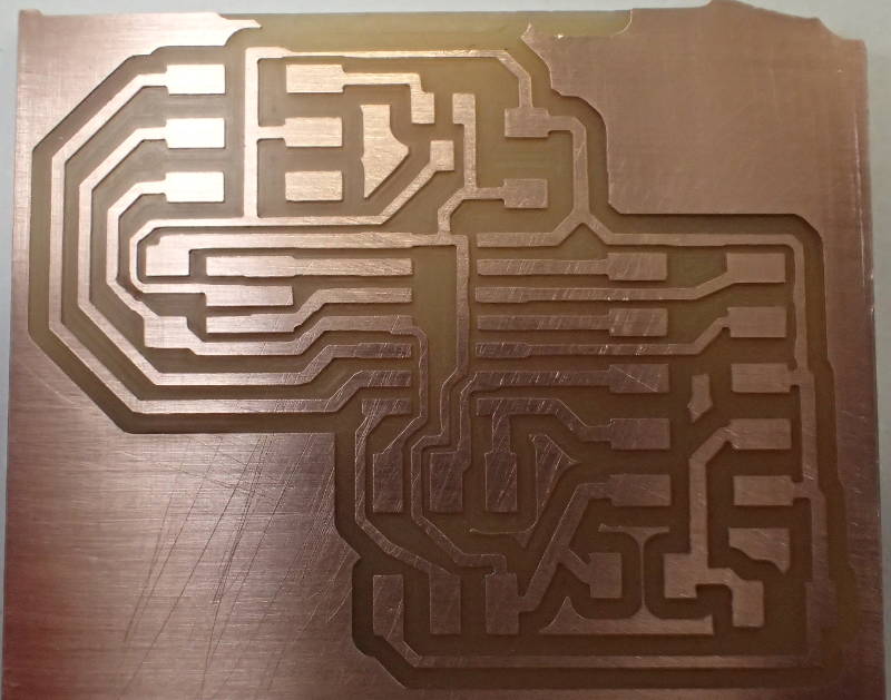 I carved between those traces with a broken 1/64in bit. Note the uneven top edge of the board, I went really close to a previous cut and only just got away with it. Waste not, want not.
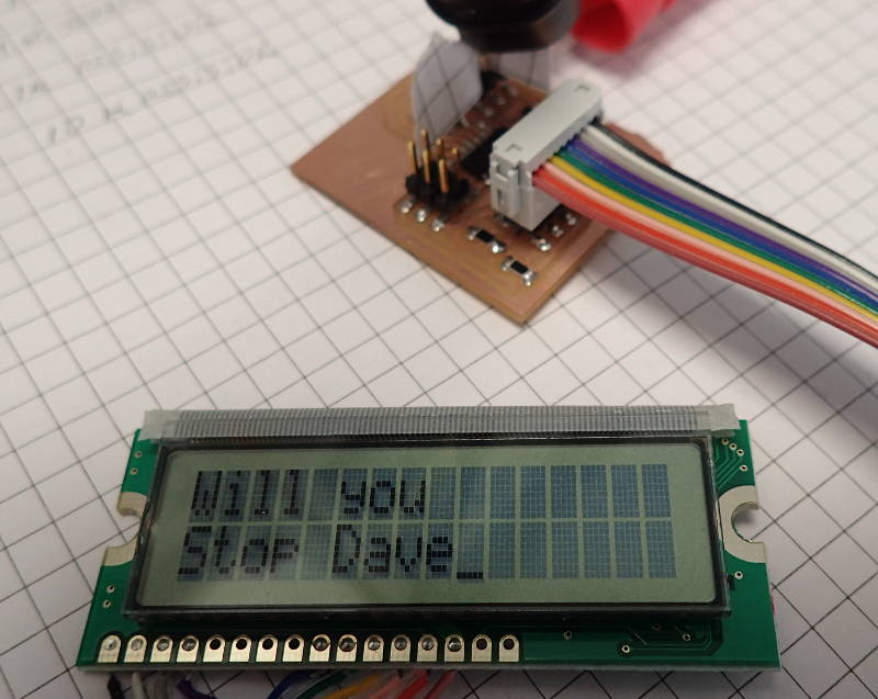 Making the board functional went without a hitch.
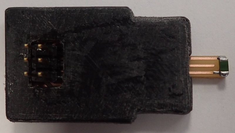
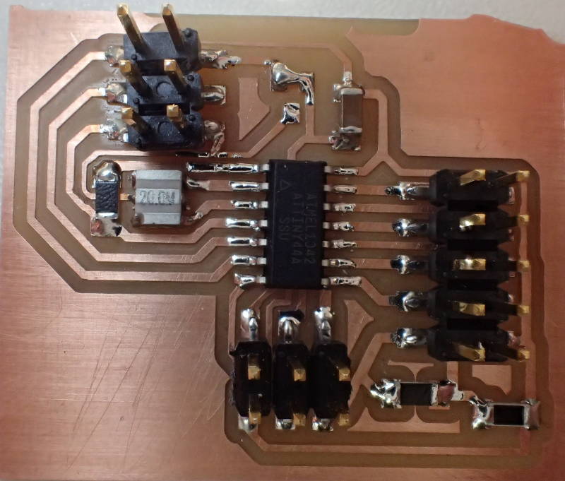
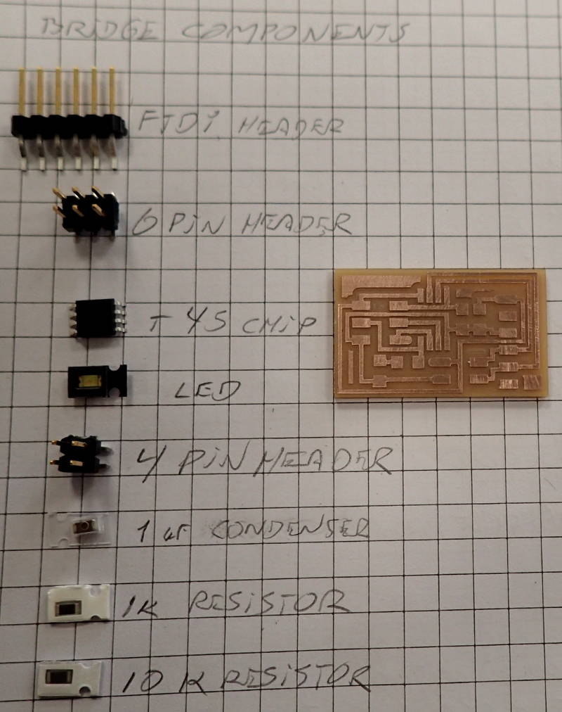 Now, to make a bus bridge board.
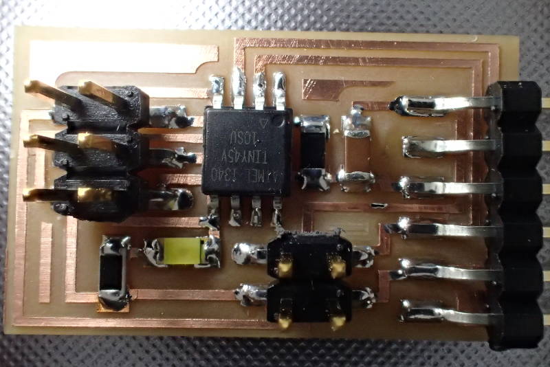 And there it is, ready for programming.
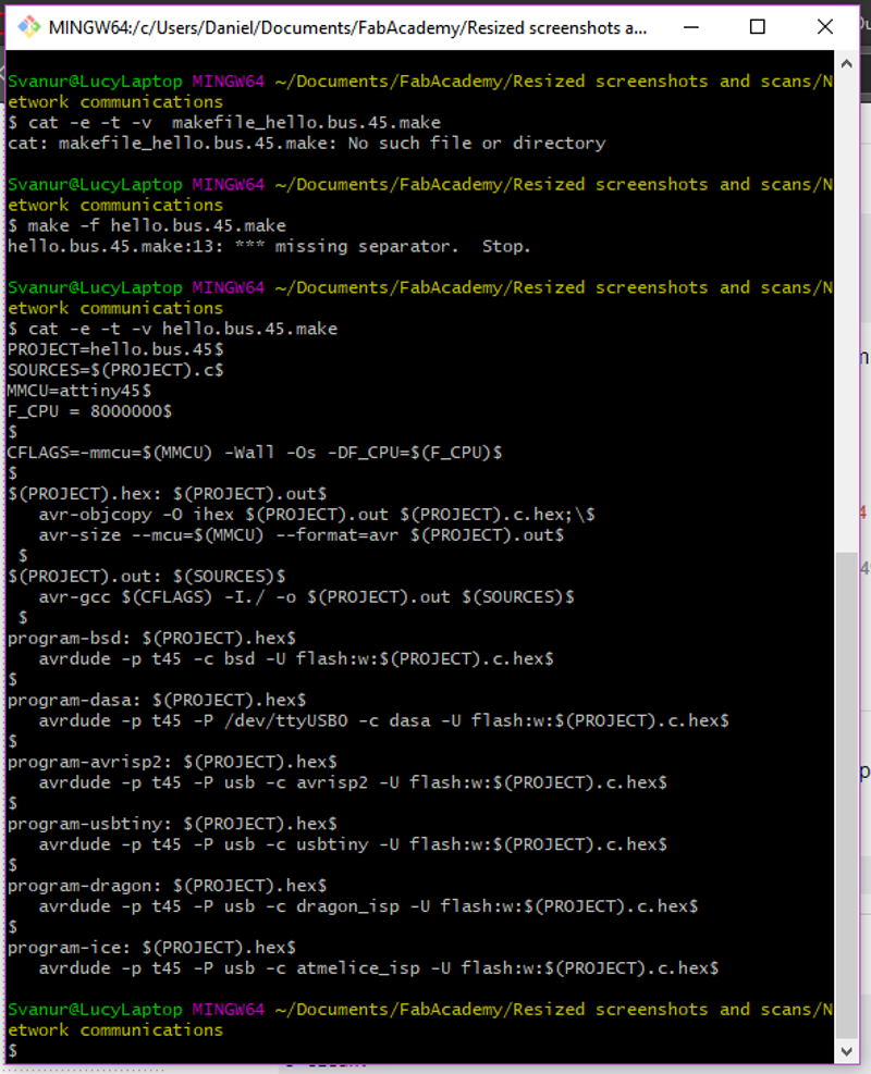 Try as I might, I could not run the Make file, there was always an error message saying: hello.bus.45.make:13: ***Missing separator. Stop.
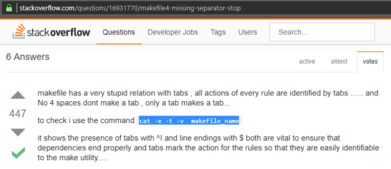 I googled that message and it seemed to have something to do with the lines in that Makefile being started with spaces whereas apparently they should be started with a tab. I opened the Makefile in a text editor and did backspaces in front of all the indented lines and reindented them with a tab, saved the file and tried running it again.
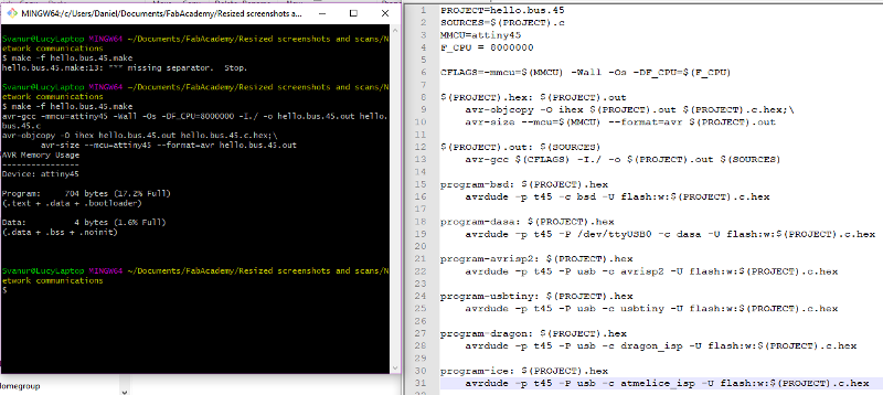 This time it worked.
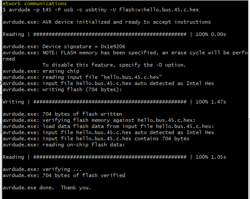 Finally, everything worked and avrdude flashed the bus bridge board.
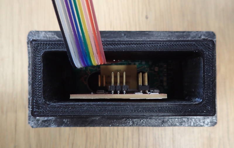
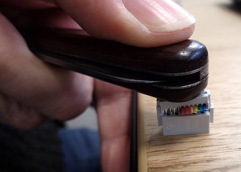 I put together a ribbon with four connectors. We did not have any 6 pin ones, so I used 10 pin connectors.
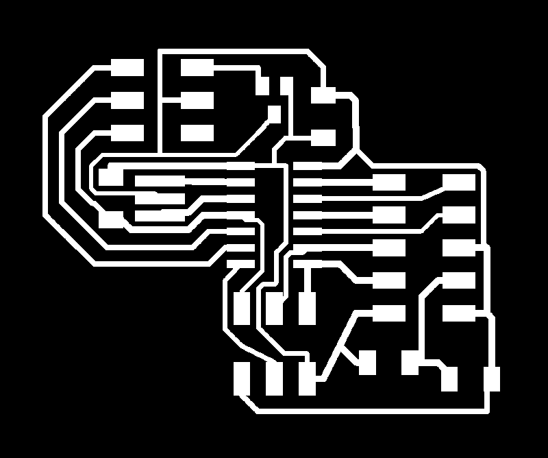
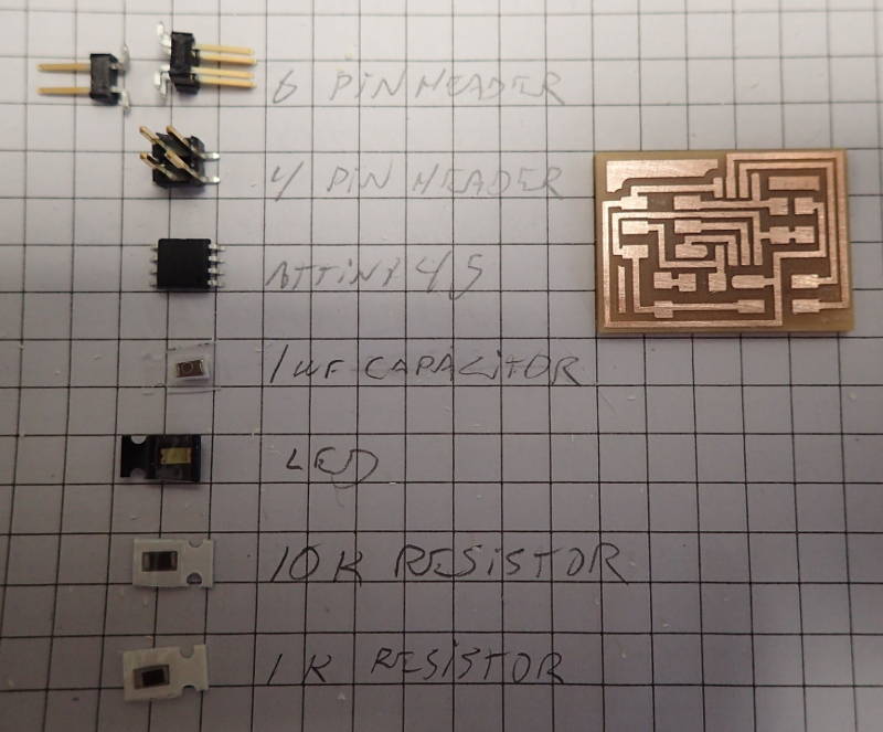 Node board ready to populate.
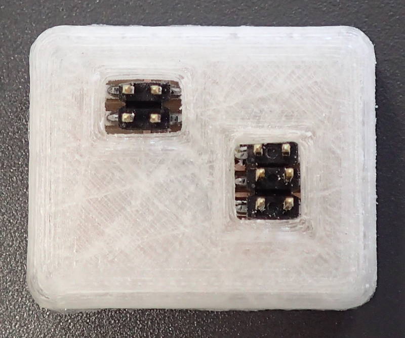
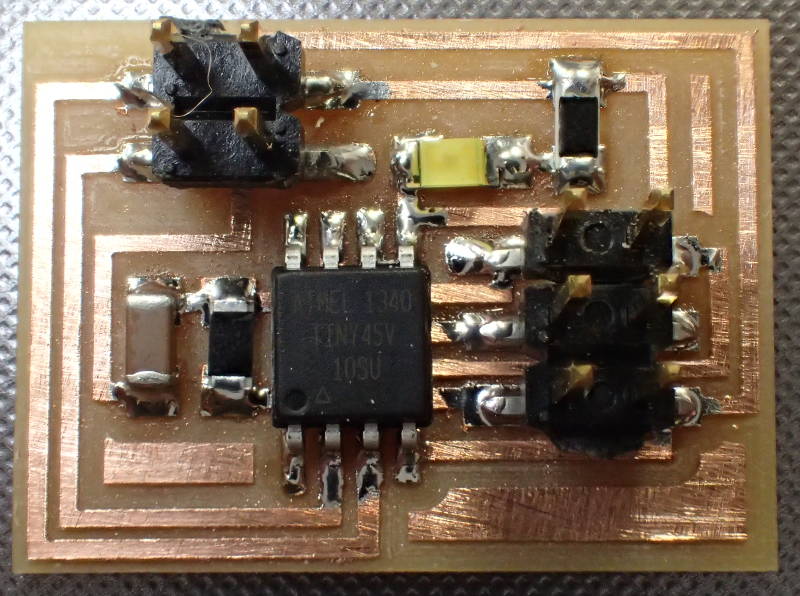 Finished node board.
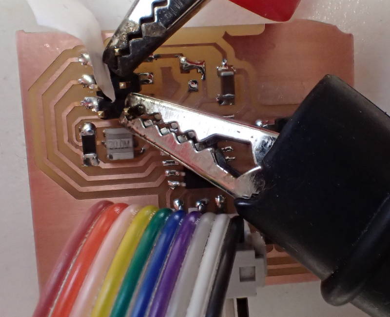
 Here is an LCD board starting it's ardous journey towards it's destiny - a hybrid LCD-communications node. This involves some violent physical post-processing, like digging through one trace, bridging between two others and removing the voltage regulator.
 Flashing the board as a communications node.
 Rough and ready rework.
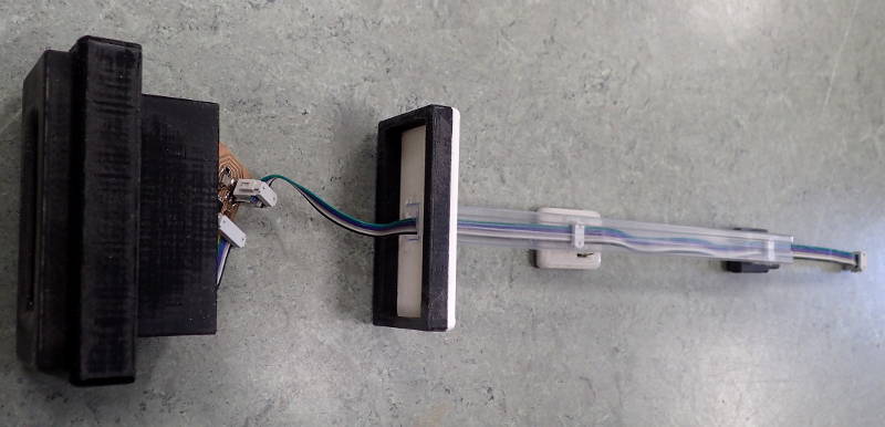
Here is the serial network as it will be used in my final project. It has three modules, a master networking module, a temperature sensor and an LCD display. A Hello.bus.45.bridge module acts as a master and a hello.temp.45 and hello.LCD.44 cards, both modified to act as network cards, act as slaves.
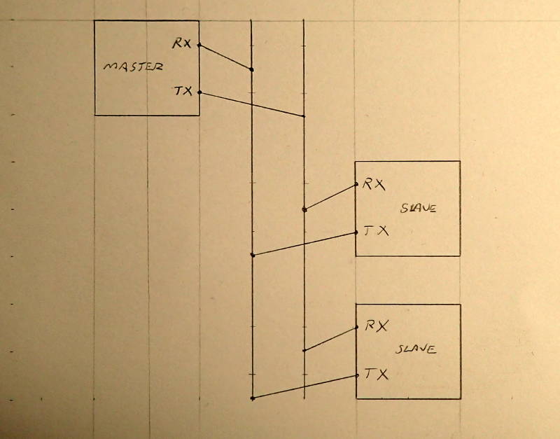
The idea is that the master transmits on it's Tx line and the slaves listen on their Rx line. The slaves then respond on their Tx line and the master receives on it's Rx line. As soon as the slaves have finished reponding, they shut up by changing their transmit pin from output to input and enabling their pullup resistor, thus keeping the line free from chatter. The master takes 64 readings from the temperature sensor and averages them out, then sends the result to the LCD module.
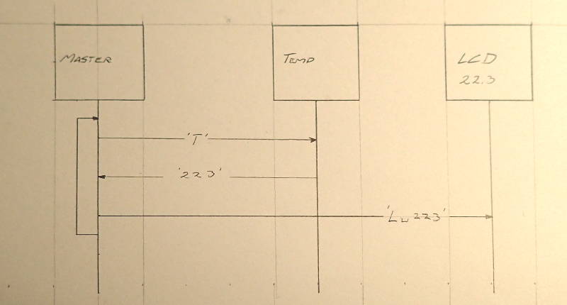
The master asks for a temperature reading by sending out a code representing the letter T. The temperature sensor responds by sending back a reading that is ten times the actual temperature, so 23.3 degrees will be 233. Then the master module sends an L, followed by a space and the number 233 to the LCD module. This process then repeats.
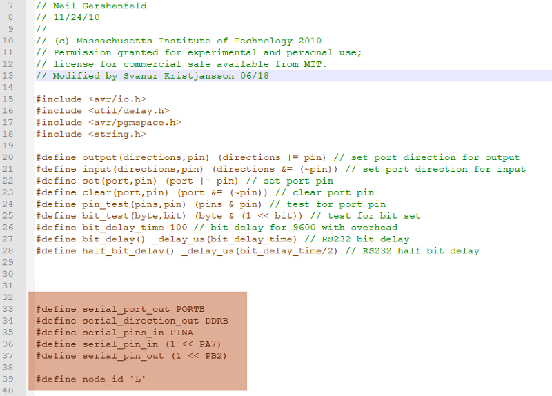
The C code for the LCD card had to be modified to also work as a code for a networking node.
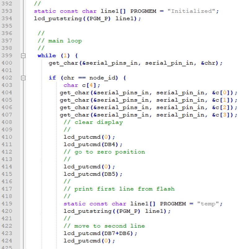
The original code had the card saying Hello World, but now when it is turned on, it says Initialized, then the upper line changes to display the word temp, and the lower line will display the data it receives from the temperature sensor as a three figure number with one decimal point, as degrees celsius.
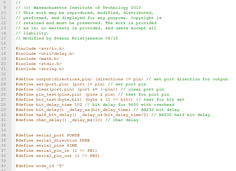
The C code for the temperature sensor also had to have code from the Hello World networking node pasted into it.
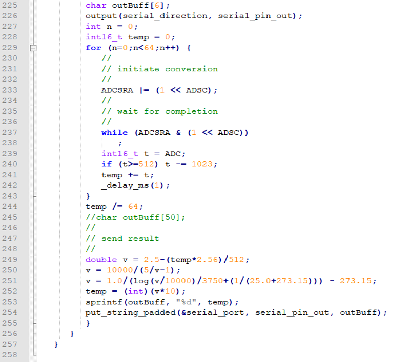
The code had to be changed to take the reading from the temperature sensor and convert it into numbers that could be sent to the LCD bus board and displayed as degrees celsius.
The card itself is just the original Hello.bus.45.bridge card.