Assignment: Measure something: add a sensor to a microcontroller board that you have designed and read it.
 The first attempt at milling the board resulted in some random lines instead. I do not know what caused it, but carefully jiggling all the connectors between the Modela and it´s Raspberry pi solved that problem.
 Time to try again, it should fit nicely on there.
 Always check the coordinates of the traces before setting the coordinates for the interior into Fab modules.
 It came out well.
 Hello.Temp.45
 Now to lay down a new board, making sure there are no specks of dust or adhesive left on the sacrificial surface.
 The board sloped slightly towards the left edge, so it did not get cut completely through. Recutting with Z0 set at -0.1mm worked.
 The board came out quite fuzzy.
 Very, very fuzzy, in fact.
 A bit of polishing took care of that.
 Always check the bit for cleanliness before cutting. The 1/64 bit had adhesive residue caked in the flutes.
 The 1/32 bit had even more.
 Ready to populate the board.
I decided I needed more practice in making boards, so I made the Hello.Load.45 and Hello.txrx.45 boards to help me get the hang of Fab Modules, the Modela MDX20 and the soldering process.
 List of components.
 Hello.Load.45
 List of components.
 Hello.txrx.45
 I used avrdude to run the hello.temp.45.make file.
 I used avrdude with the resulting .hex file to flash the board with my programmer.
 Now I used Python to install numpy
 Also pyserial.

 The hello.temp board can function as a temperature sensor.
 I redrew the hello.temp board to incorporate an extra header. I could not get it to work, so I opened a picture of the original board as well as mine side by side in Gimp and followed the traces by filling them in different colors with the paint bucket. This showed up some missing traces.
 I connected the missing traces up the best I could with jumpers, but still the board would not work.
 I dismantled the board, salvaging all the components, milled a new one and populated it with the same components. However, in redrawing tha board, when eliminating the errors in the first one, I introduced a new error, one different trace was now missing.
 The fresh board with second-hand components and missing trace. I soldered a jumper across, but could not make the board work. I put this down to using components that I had hacked off the other board.
 Please sit back and enjoy our light programme of ongoing dadaism..
 I milled yet another board, properly this time, but still it would not work. I had some struggle getting the Modela to cut the board free, try as I might, I could not get it to cut deeply enough. Eventually it dawned on me that no amount of software tweakage would fix things, I simply had installed the milling bit too deep in the chuck, the machine was bottoming out when it had cut 0.6mm.
 I showed my problem to Arnar Dadi, who was quick to spot one glaring omission. In my stressed out quest to debug the boards, I had been trying to program them without using the programmer. Using that, things improved dramatically, I now have two perfectly functioning hello.temp.45 boards, as the one I had put a jumper across turned out to be a good one as well.
 I milled a new board without an FTDI header, reshaped to fit in a small enclosure with the temperature sensor jutting out, for my final project.
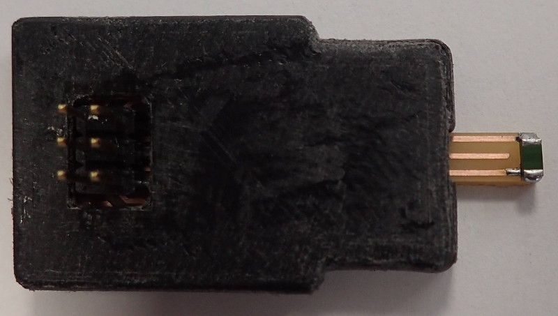 Here it is in it's 3d printed home.

 M41a Pulse rifle.
Here are downloadable full resolution files of the traces and interior of the temp. sensor, as well as the Eagle .brd and .sch files.
Here are the downloadable Eagle .sch and .brd files of the temp. sensor.