Assignment: Group assignment: characterize the specifications of your PCB production process. Individual assignment: make an in-circuit programmer by milling the PCB, then optionally trying other processes.
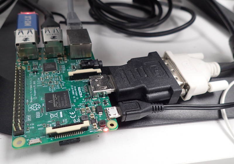
The lab has two Modela mdx 20s, one set up to scan, the other to cut. The one we used is driven by a Raspberry Pi and is wirelessly operated from any computer using Fab Modules.
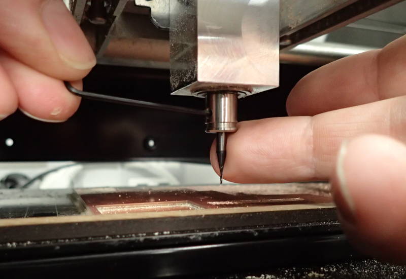
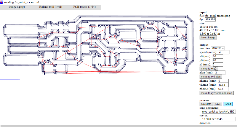
 We loaded a line test image from the Electronics Production page. We pressed the Calculate button, which had to be done on a laptop or pc, as the Raspberry Pi is not powerful enough to handle it. After a short while the toolpath was displayed in the screen, set to cut with 4 offsets to provide the right width for the traces. The bit was placed in the collet so it would not touch the board when put in the y0 position. It was then moved so it was right over the starting point, this was done by measuring where a suitable starting point would be on the board and punching in the x0 and y0 positions. The bit was now loosened whilst holding a finger against it, so it came to rest on the board, but did not crash into it, which could have damaged the bit. While still loose, the bit was rotated slightly back and forth to dislodge any possible speck of dust which might have thrown the height setting off and then tightened, making very sure not to overtighten the tiny grub screw.
 Now we made the machine move to xy0 zjog, which was set at 2mm above the board, to keep a safe clearance. When the milling started, it soon became apparent that the pcb was not level, as there were areas where the bit did not touch it. This is to be expected when attempting to use a pcb that has been placed in the machine by unknown persons and been there for an unknown amount of time.
 So the pcb was peeled off the sacrificial plate underneath it, along with any trace of double sided tape and a fresh one put in it´s place. We loaded an image of the Fab Tiny ISP from Brian´s site in the individual assignment page. This was the trace, we had to make sure to have a 1/64in bit in the machine to mill the trace, but a 1/32in bit to mill the outline, to detach the finished board after milling. Everything was now ready, Arnar's piece was in the machine and it started milling. Half way through, the machine inexplicably took off at a random tangent and plowed through an MDF guide that was used to locate the board on the machine's bed.
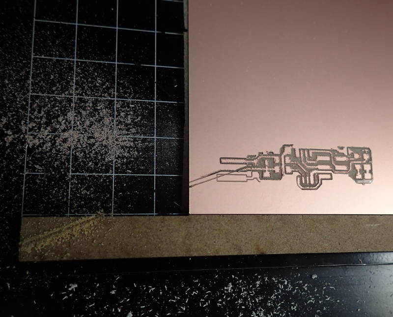
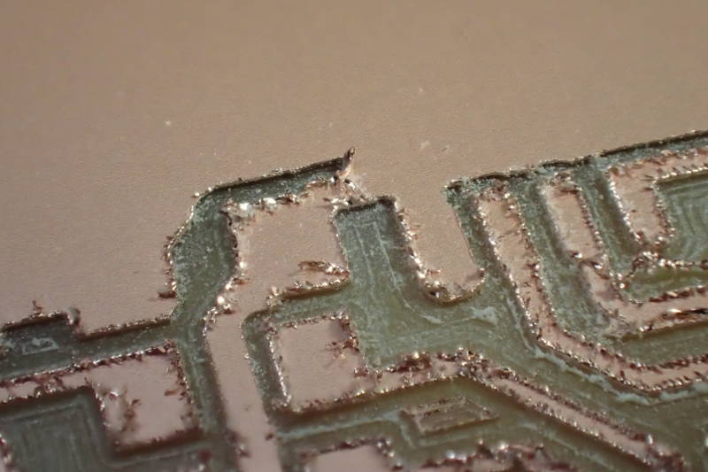
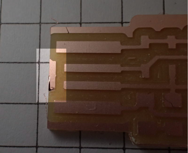
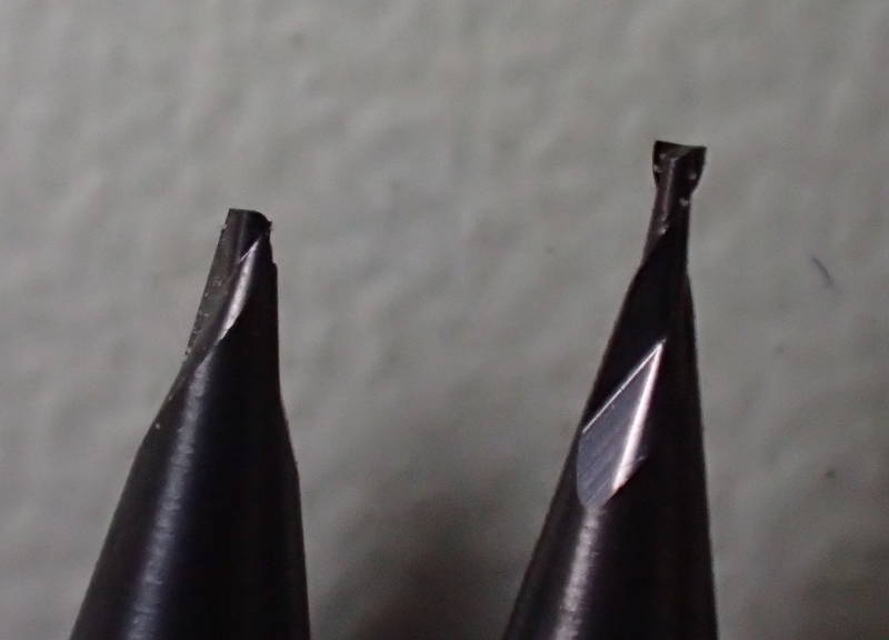 This snapped the tip off the bit. Bas Withagen took a look remotely at the Raspberry Pi, but in the end the culprit seems to have been some untraceable, random glitch. Upon close examination of the half milled piece we saw some very rough edges, it would not have been advisable or even possible to continue using the bit, it must have been completely dull.
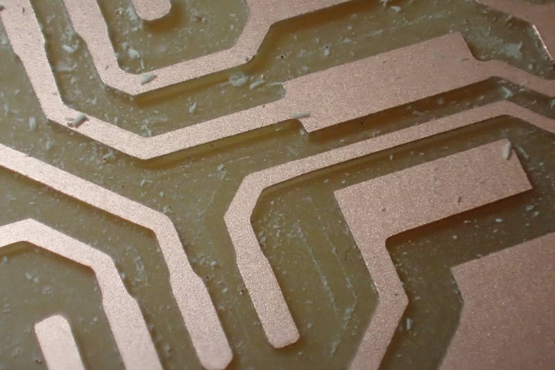
 A fresh 1/64in bit was found and this time it milled with perfectly crisp edges.
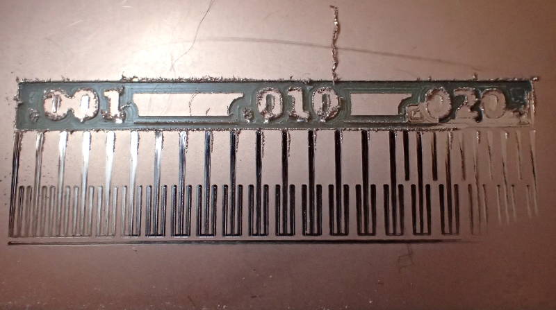
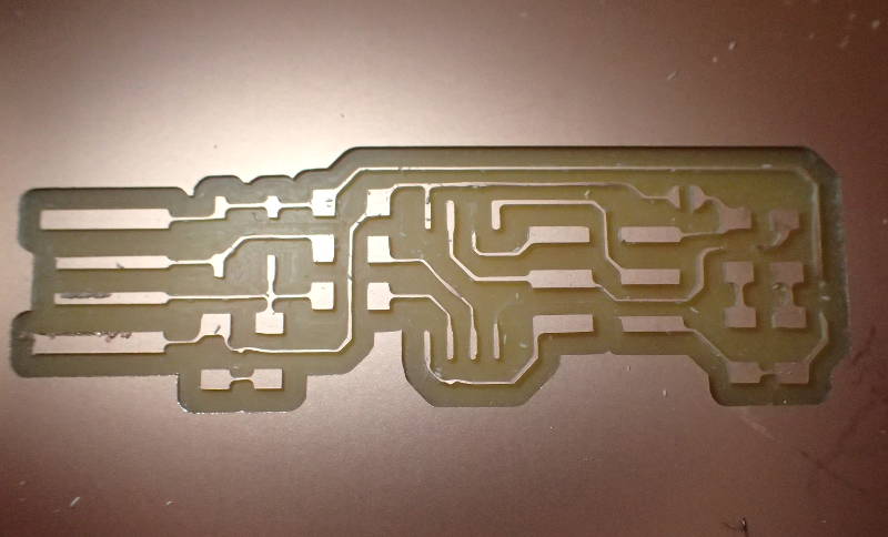
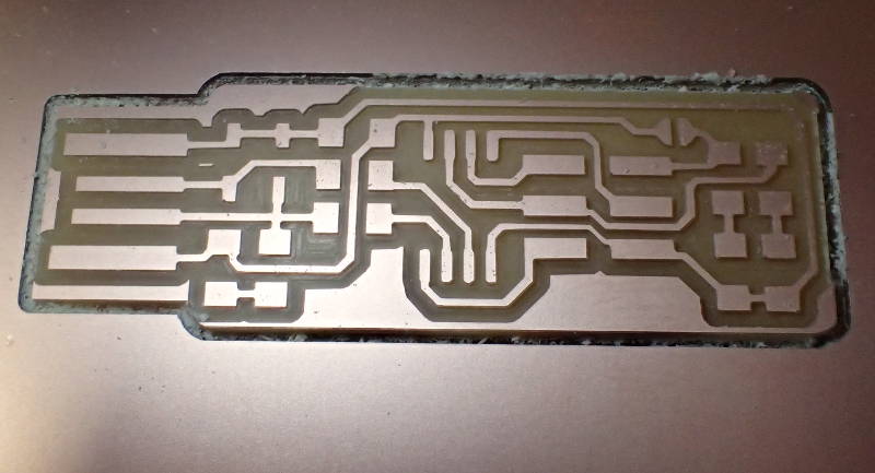
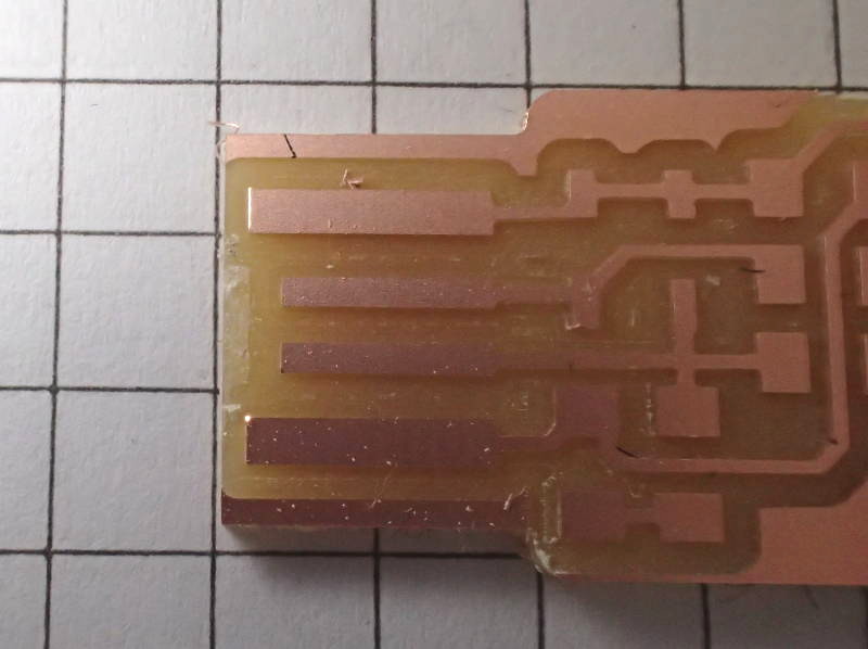
 When my turn came to mill my piece, I measured carefully where the starting point should be and started the job. Half way through I could not resist brushing the dust off and taking a look, then I discovered that I had forgotten to change the bit from the previous job, which was an outline using a 1/32in bit. This, with 4 offsets made an interesting looking piece with some extremely skinny traces.
 I waited for the machine to finish, as it was just about to anyway and found a new starting point and set up the fresh 1/64in bit.
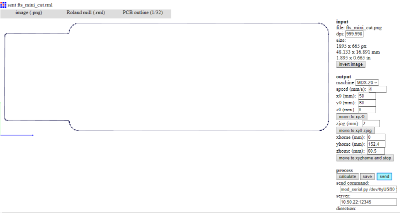
 This time everything came out perfect, I loaded an image of the surround, had the toolpath calculated, changed back to the 1/32in bit and made sure to set the same starting point.
 After a short while, my first circuit board was ready to pry off the tape.
The last thing remaining before soldering the surface mount components to the board was to pry off a bit of copper to ensure that the USB connection would not short out.
This was well stuck down, but came away cleanly enough.
Next order of business was to solder the components to the boards, which was surprisingly easy considering I had never attempted to solder surface mount components before. We had some good instructions how to hold the component with tweezers and tack one side down first and push the component down on the board so it would be level, the temperature-controlled soldering iron and thin gauge solder made this easy.
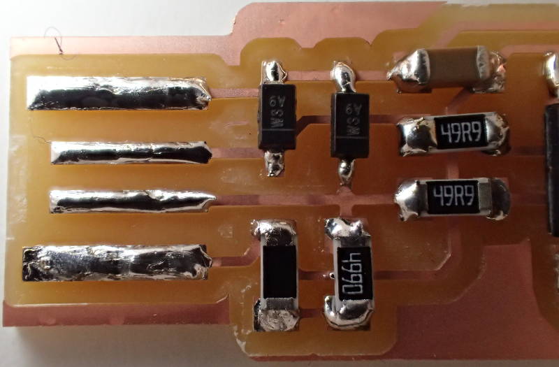
This looked ever so pretty with the naked eye - in close-up, not so much.
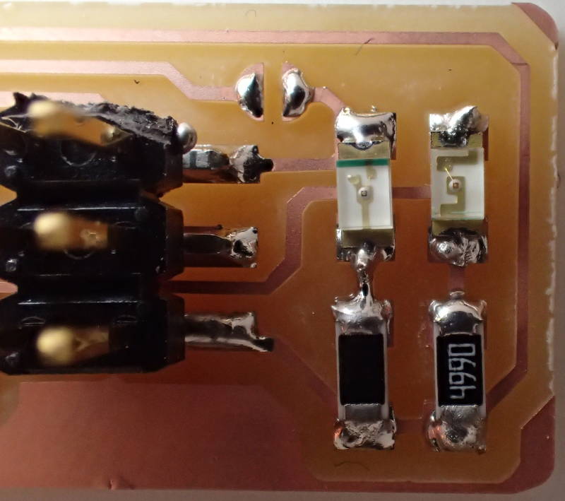 The left LED is soldered the wrong way around.
When the programmer was plugged in to a USB port, no light came on, upon closer inspection I saw that I had soldered one of the LEDs the wrong way around.
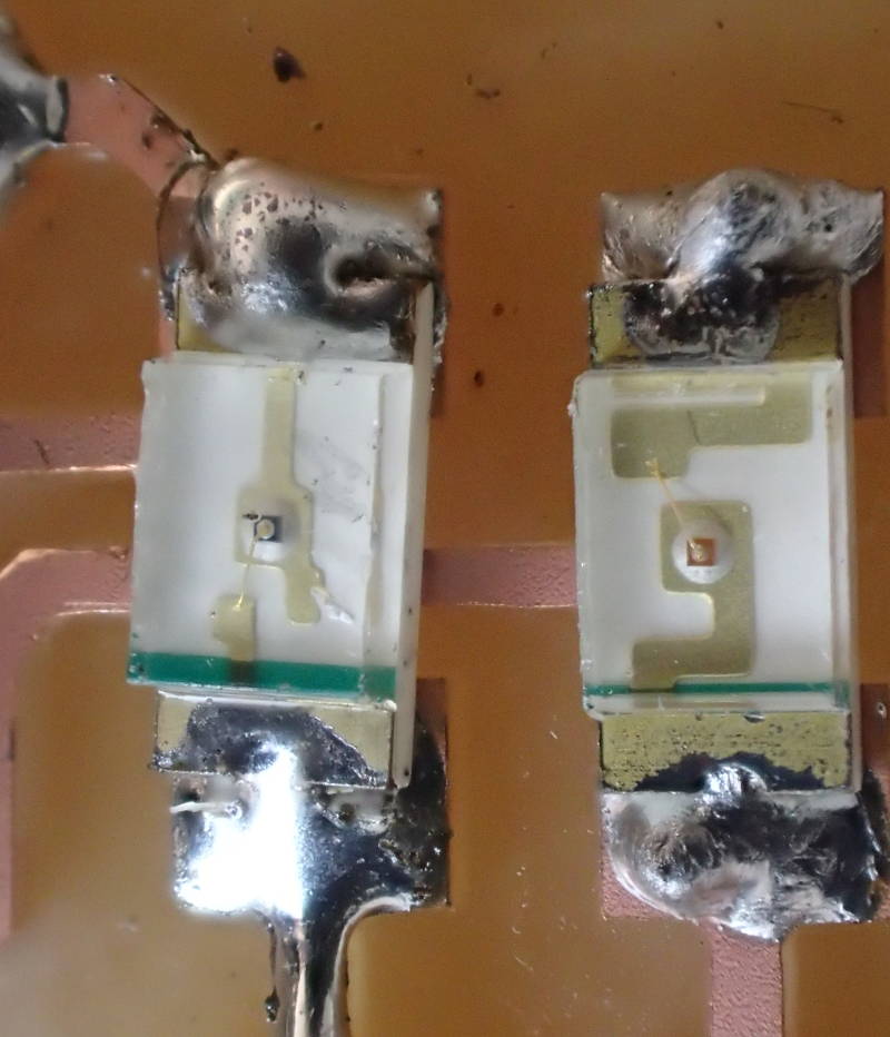 This gave me an opportunity to try out how to desolder a surface mount component, after some wrestling with the desoldering wick the LED came off and was swiftly reoriented and duly lit up when plugged in.
I decided to jump the gun and go for extra credit and start programming the programmer, I have Windows 10 on my laptop, so I had to download the programs individually. Try as I might, though, I could not get Avrdude to work.
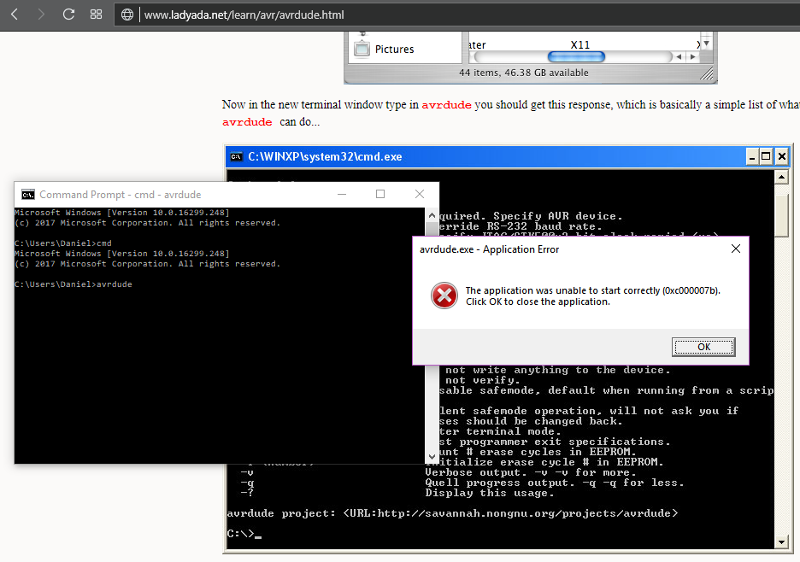 It always came up with a 0xc000007b error, which apparently some other Windows 10 users have encountered following an update. The problem is supposedly a corrupted .dll file and there are plenty of remedies to try, but none of them worked. The laptop did work smoother after this workout, though. I decided to create a new partition and install Ubuntu as a dual boot, then I downloaded the software using the sudo apt install avrdude gcc-avr avr-libc make command. That worked, but I need further instructions to be able to find what I downloaded, being a complete Ubuntu novice.
Little did I know that Avrdude can not be started by double-clicking on the executable, when Bas Withagen took a look at it, he fired up Gitbash and typed in Avrdude, lo an behold, it had been working just fine the whole time.
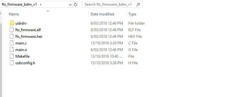 I downloaded the firmware source code, extracted it and ran Make and got a fts_firmware.hex file. I was using a usbtiny programmer, so I did not modify the makefile. I connected Arnar's programmer to an USB2 port on my laptop through a USB extension and the computer recognized it right away.
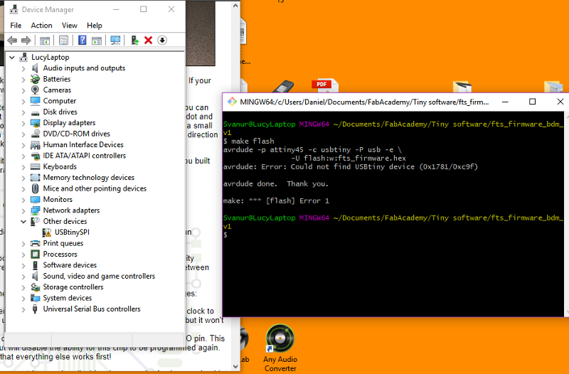 I gonnected my programmer to it and found the folder containing the firmware file and selected Git bash from here. Then I typed in Make flash, but got an error message.
I had omitted one step, to install Zadig and use it to install drivers for the programmer on my laptop.
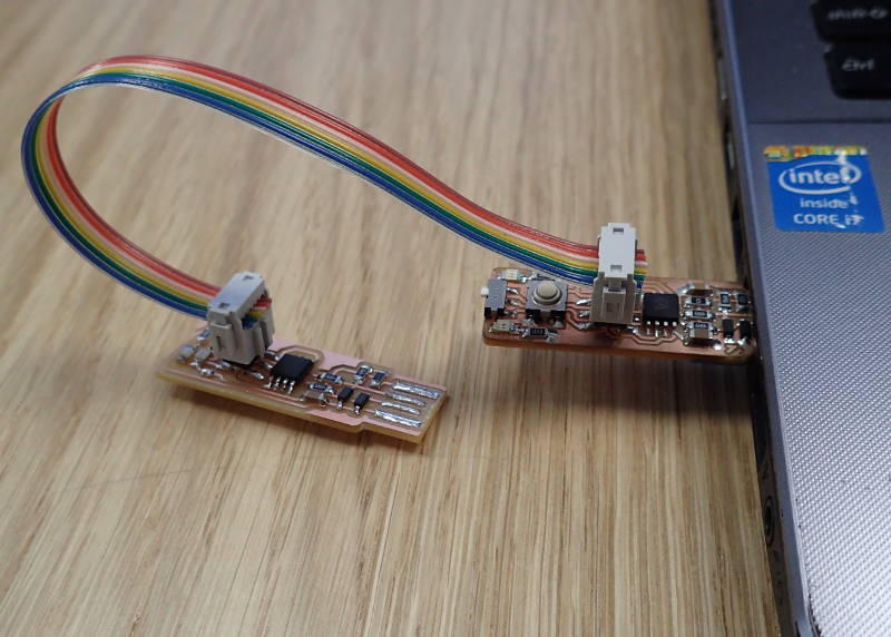 It took me a while to realize that both programmers; my blank one and the one used to program it, had to be connected to a USB port at the same time for them both to receive power. I had been trying to plug just the one in and piggyback the other one off it.
I also had problems installing the drivers, as Zadig did not recognize my programmer, which of course was not a programmer yet and there was nothing for it to recognize. Finally, when I plugged the existing programmer in, it showed up as a USBtinySPI and I clicked on Install Driver. Then it was just a matter of connecting both programmers and plugging them both in, running Make flash and then Make fuses, disconnecting the programmers, reconnecting mine to a USB port to make sure it showed up in Zadig and Device manager and then running rstdisbl to blow the reset fuse and finally desolder the bridge on the programmer.
It took me a while to realize that both programmers; my blank one and the one used to program it, had to be connected to a USB port at the same time for them both to receive power. I had been trying to plug just the one in and piggyback the other one off it.
I also had problems installing the drivers, as Zadig did not recognize my programmer, which of course was not a programmer yet and there was nothing for it to recognize. Finally, when I plugged the existing programmer in, it showed up as a USBtinySPI and I clicked on Install Driver. Then it was just a matter of connecting both programmers and plugging them both in, running Make flash and then Make fuses, disconnecting the programmers, reconnecting mine to a USB port to make sure it showed up in Zadig and Device manager and then running rstdisbl to blow the reset fuse and finally desolder the bridge on the programmer.
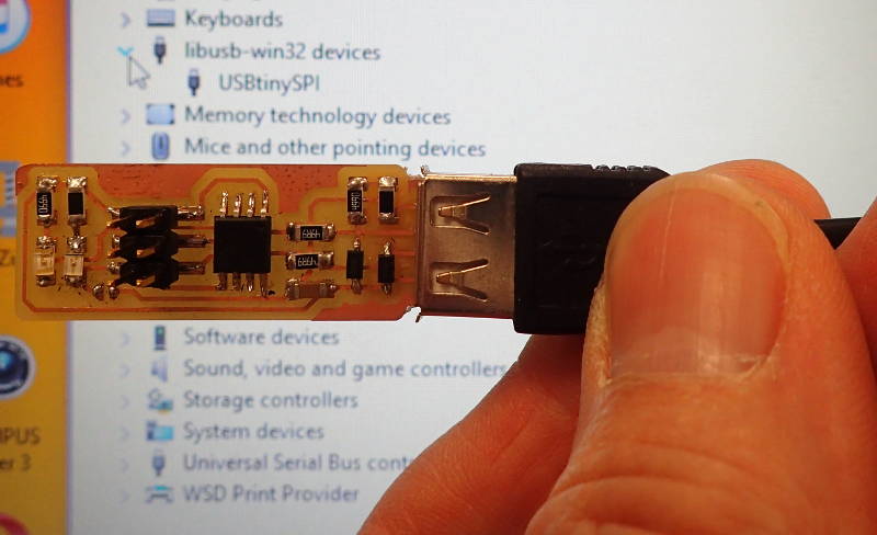 The Tiny programmer could now be programmed and the computer recognizes it, aided by a layer of tape applied to the back side of the USB connection, to facilitate good contact.