Assignment: Redraw the Echo Hello-world board, add (at least) a button and LED (with current-limiting resistor), check the design rules, make it, and test it. Extra credit: Measure its operation. Extra extra credit: Simulate its operation.
I downloaded Eagle to set up the schematic for the Hello world board and draw it's traces and export them as black and white image to be milled on a Modela MDX-20 via Fab modules. The following day Bas Withagen did a tutorial on how to do this. I tried to see how far I could go unassisted, I had trouble finding the component libraries, but found some by going a couple of years back in the student archives and browsed until I found a link to them. It turned out the linked content was somewhat out of date, as the libraries are in a continuing process of being updated, but as a result I could just about follow the next mornings tutorial although I was late and missed the first 15 minutes.
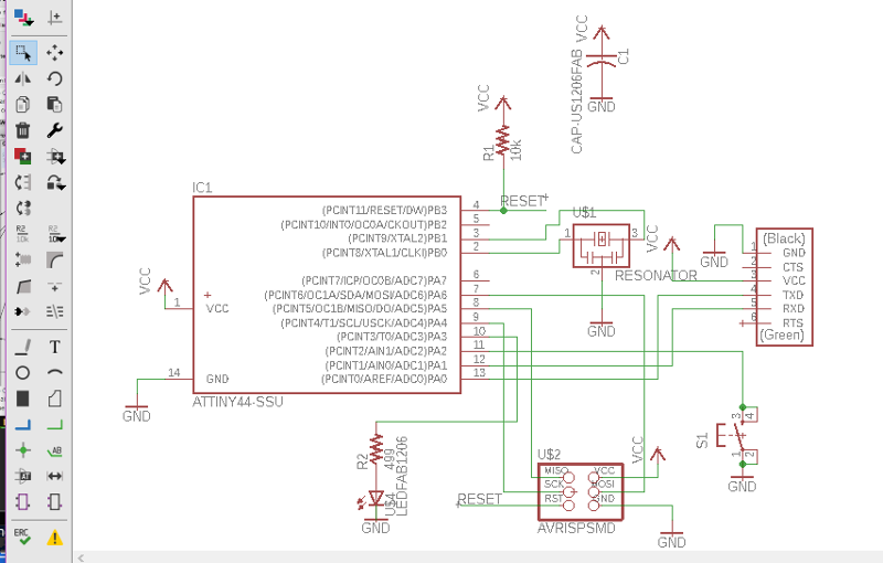 The next day I studied the recording of the tutorial, built the schematic and tried to see if I could rout the traces on the board myself. At this point I was completely unaware that in the Fab academy's website's tutorials, the Introduction to Eagle one had a detailed step by step walkthrough with a sample schematic and board.
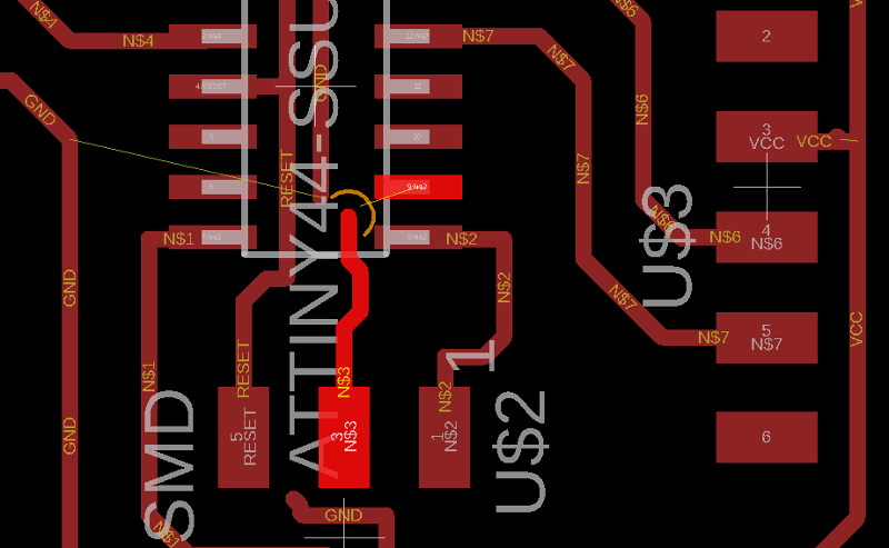 So I persisted for a while in creating the most absurd abstract art with at least three airwires left to trace each time, but when I found the tutorial the process became more straightforward.
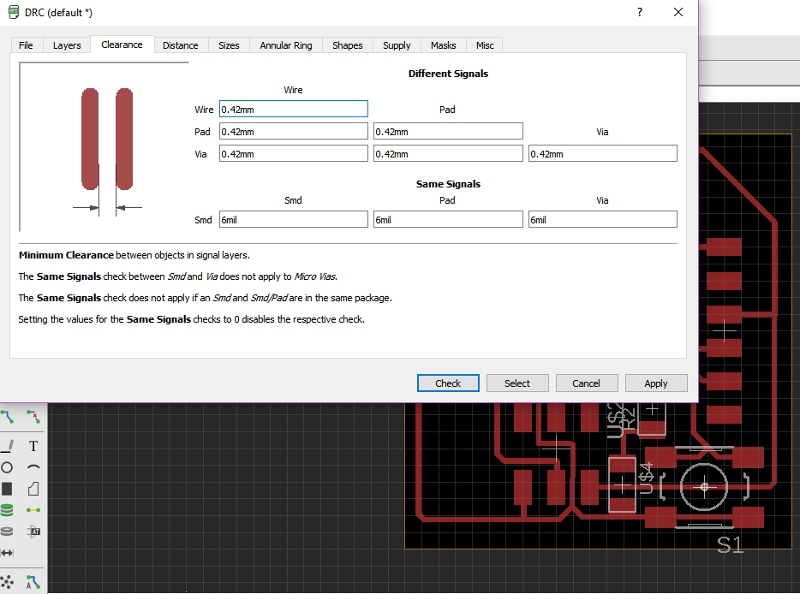 I ran into a snag where Eagle refused to draw traces in the areas with the least clearance, but tweaking the design rules to set the clearances to 0.42mm fixed that.
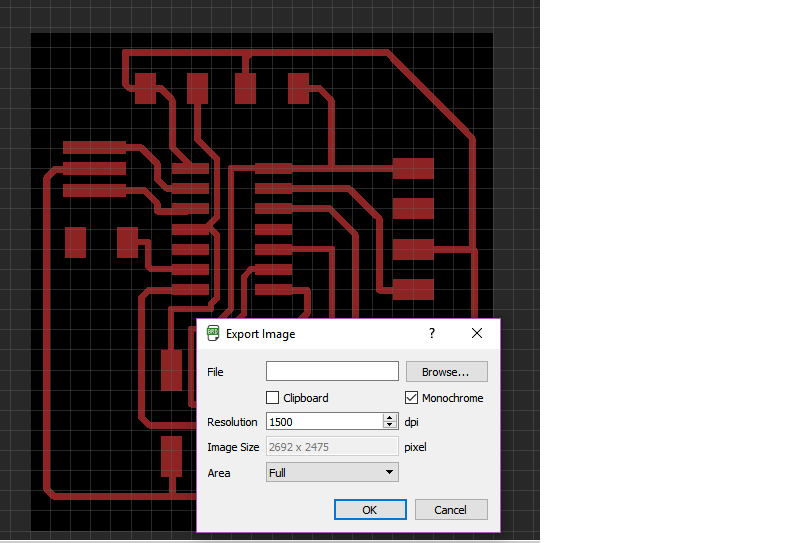 I exported the board as a 1500dpi .png image, along with it's outline and opened it with Fab modules.
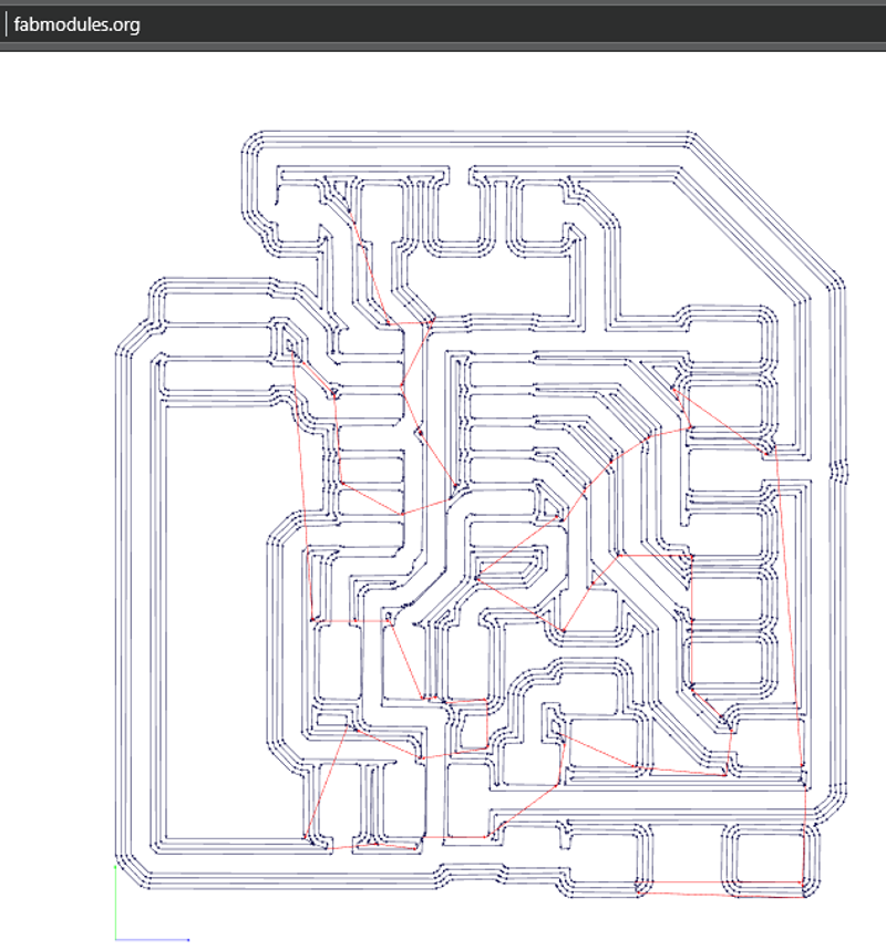 It looked to me like a couple of areas might not get cut due to very narrow clearances, although the design rules check in Eagle had given the all clear. Linda Wanders suggested that I crop the image down to the suspect area and milled a sample, that way it would be so small that not too much time and PCB board would be wasted.
I did this and it appeared it would get milled just fine, although on the test area, the traces did not get milled all the way through. I guessed that was because the PCB had subsided slightly towards the edge and decided to mill the complete board by the inside edge of the test piece. This turned out well and I started picking components for the board.
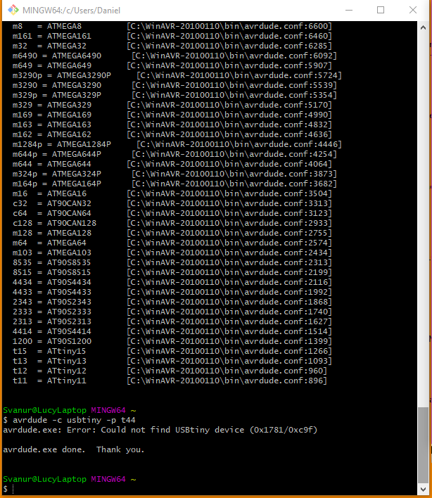 Bas gave us a tutorial on how to program the board with a programmer. Arnar Dadi did this and his board worked. I followed the same steps, using the same software on my laptop, but Avrdude would not find the attiny44 board.
Arnar Dadi offered me to try programming my board using his pc and the same programmer, as I have not finished programming mine, and that time everything worked flawlessly, so there must be some incompatibility with the AVR toolchain or a power supply issue as my laptop was running on battery at the time.
It turned out I had forgotten one thing. Once I had downloaded Zadig and used that to install the drivers for the programmer on my laptop, it worked as it should.